


Surge Protective Devices
SPD50K Series

SPD50K
Safety Information
Important Information
Read these instructions carefully and look at the equipment to become
familiar with the device before trying to install, operate, service or maintain it.
The following special messages may appear throughout this bulletin or on the
equipment to warn of potential hazards or to call attention to information that
clarifies or simplifies a procedure.
The addition of either symbol to a “Danger” or “Warning” safety label
indicates that an electrical hazard exists which will result in personal
injury if the instructions are not followed.
This is the safety alert symbol. It is used to alert you to potential
personal injury hazards. Obey all safety messages that follow this
symbol to avoid possible injury or death.
DANGER
DANGER indicates a hazardous situation which, if not avoided,
will result in death or serious injury.
WARNING
WARNING indicates a hazardous situation which, if not avoided,
could result in death or serious injury.
Please Note
CAUTION
CAUTION indicates a hazardous situation which, if not avoided,
could result in minor or moderate injury.
NOTICE
NOTICE is used to address practices not related to physical injury. The safety
alert symbol shall not be used with this signal word.
Electrical equipment should be installed, operated, serviced, and maintained only
by qualified personnel. No responsibility is assumed by Appleton Grp LLC d/b/a
Appleton Group for any consequences arising out of the use of this material.
A qualified person is one who has skills and knowledge related to the
construction, installation, and operation of electrical equipment and has received
safety training to recognize and avoid the hazards involved.

SPD50K
Precautions
DANGER
HAZARD OF ELECTRIC SHOCK, EXPLOSION, OR ARC FLASH
• Apply appropriate personal protective equipment (PPE) and follow safe electrical work practices. See NFPA 70E,
NOM-029-STPS or CSA Z462.
• This equipment must only be installed and serviced by qualied electrical personnel.
• Turn o all power supplying this equipment before working on or inside equipment.
• Always use a properly rated voltage sensing device to conrm power is o.
• Replace all devices, doors and covers before turning on power to this equipment.
• This equipment must be eectively grounded per all applicable codes. Use an equipment-grounding conductor to
connect this equipment to the power system ground.
• Conrm the SPD voltage rating on the module or nameplate label is not less than operating voltage the operating
voltage.
Failure to follow these instructions will result in death or serious injury.
WARNING: This product can expose you to chemicals including DINP, which is known to the State of
California to cause cancer, and DIDP which is known to the State of California to cause birth defects or
other reproductive harm. For more information go to: www.P65Warnings.ca.gov.
NOTICE
LOSS OF BRANCH CIRCUIT POWER / LOSS OF SURGE SUPPRESSION
• Perform periodic inspection of the surge protective device status indicator lights as part of the preventative
maintenance schedule.
• Promptly replace the surge protective device when an alarm state exists.
• Use dry contacts to signal an alarm state to the central supervisory system for unmanned, inaccessible, or
critical installations.
• Use multiple surge protective devices to achieve redundancy for critical applications.
Failure to follow these instructions can result in equipment damage.
At end-of-life conditions, Surge Protective Devices (SPDs) can lose their ability to suppress power system
transient voltage spikes and attempt to draw excessive current from the line. This SPD is equipped with
overcurrent and overtemperature components that will automatically disconnect the surge suppression
elements from the mains should the surge suppression elements reach end of life. Tripping of the branch
circuit breaker or fuse feeding the SPD can occur. Mitigate the tripping of the branch circuit breaker or fuse
feeding the SPD by coordinating the surge suppression elements with the branch circuits.
Page: 1

SPD50K
DANGER
HAZARD OF ELECTRIC SHOCK, EXPLOSION, OR ARC FLASH
• Do not energize the surge protective device until the electrical system is completely installed, inspected and
tested.
• Ensure all conductors are connected.
• Verify the voltage rating of the device and system prior to energizing.
• Perform high-potential insulation testing, or any other tests where surge protective device components will be
subjected to voltages higher than their rated turn-on voltage, with the neutral and surge protective device disconnected from the power source
Failure to follow these instructions will result in death or serious injury.
Introduction
DANGER
HAZARD OF ELECTRIC SHOCK, EXPLOSION, OR ARC FLASH
• Apply appropriate personal protective equipment (PPE) and follow safe electrical work practices. See NFPA 70E,
NOM-029-STPS or CSA Z462.
• This equipment must only be installed and serviced by qualied electrical personnel.
• Turn o all power supplying this equipment before working on or inside equipment.
• Always use a properly rated voltage sensing device to conrm power is o.
• Replace all devices, doors and covers before turning on power to this equipment.
• This equipment must be eectively grounded per all applicable codes. Use an equipment-grounding conductor to
connect this equipment to the power system ground.
Failure to follow these instructions will result in death or serious injury.
Proper installation is imperative to maximize the SolaHD SPD50K's effectiveness and performance. Follow
the steps outlined in this instruction manual to ensure proper installation. Read the entire instruction manual
before beginning the installation. These instructions are not intended to replace national or local electrical
codes. Check all applicable electrical codes to verify compliance. Installation of these surge suppressors must
only be performed by qualied electrical personnel.
Unpacking and Preliminary Inspection
Inspect the shipping container for damage before unpacking the device. Remove the packing material and
further inspect the device for shipping damage. If any damage is found, immediately le a claim with the
shipping company.
Parts List
• 1 - SPD50K Surge Protective Device (SPD) including 3 ft (approximately 1m) conductors
• 1 - 3/4 in. conduit nut
• 1 - L bracket mounting kit with two pan head screws
Page: 2

SPD50K
Storage
The device should be stored in a clean, dry environment. Storage temperature is -67 °F to +149 °F (-55°C to
+65°C). All of the packaging materials should be left intact until the device is ready for installation.
Identification Nameplate
The identication nameplate is located on the side of the unit.
Figure 1: SPD 50K Identification Nameplate
E335146
44BV
SolaHD
CW
50-60Hz
UL 1449-4
MCOV: ______
In: ________
VOLTAGE
PROTECTION RATING
L-N _______
L-G _______
N-G _______
L-L _______
MODEL: SPD50K-____
VOLTAGE: _________V
MAX RATED AMBIENT
AIR TEMP: ________
MFG DATE: _________
ENC TYPE: 1, 12, 4X
SPD TYPE: 1
UL
HOLOGRAM
Suitable For Use on a Circuit Capable of Delivering
Not More Than 200,000 rms symmetrical Amperes.
IMPORTANT: Verify the SPD is properly rated for installation on your distribution system. Conrm the surge
protective device voltage rating on the nameplate label exceeds the voltage of the distribution system
(operating system voltage) it will be installed in.
DANGER
HAZARD OF ELECTRIC SHOCK, EXPLOSION, OR ARC FLASH
• Conrm the SPD voltage rating on the module or nameplate label is not less than operating voltage the operating
voltage.
Failure to follow these instructions will result in death or serious injury.
For any questions, contact SolaHD Technical Support. See the last page of this manual for
contact information.
SPD Location Considerations
Environment
The device is designed to operate in an ambient temperature range of -40 °F to +140 °F (-40°C to +60°C) with a
relative humidity of 0 to 95% non-condensing. This device has a Type 4X housing.
Audible Noise
The device background noise is negligible and does not restrict the location of the installation.
Mounting
The device has been designed to be DIN-rail, bracket or surface mounted.
Service Clearance
The service clearance should meet all applicable code requirements.
Page: 3

SPD50K
Equipment Performance
To obtain optimum surge suppression, locate the SPD as close as possible to the circuitry being surge-limited to
minimize the wire length. Minimizing the wire length reduces the impedance between the circuitry and the SPD.
Refer to the Voltage Protection Rating (VPR) values on the SPD nameplate. These VPR values were obtained by
testing the SPD with six-inch long leads (per UL1449). For every additional foot of wire beyond six inches, the
effective VPR increases by approximately 160 volts.
Technical Data Sheet
Performance Specifications Diagnostic Monitoring
• 50kA per phase
• UL 1449 tested Inominal: 20kA
• UL 1449 tested SCCR: 200kA
• Individually fused & thermally protected MOVs
• Repetitive impulse: 5000 - 3kA - 8 x 20µs;
1000 - 10kA - 8 x 20µs
Physical Specifications Features
• Relative humidity range: 0 - 95% non-condensing
• Operating frequency: 47 - 63 Hz
• Operating temperature: -40° C (-40° F) to
+85° C (185° F)
• Response time: < 1 nanosecond
• Solid state bi-directional operation
• NEMA 4X polycarbonate enclosure—UL746C(f1),
UL 94-5VA
• Pre-wired with 3 feet (0.9 meter) of
#10 AWG conductor
• Typical connection: 30A breaker
• Weight:1.60 lbs (0.73 kg)
Quality, Standards & Validation
• cULus Listed
• Type 1: UL 1449, CSA 22.2 No. 269.1
• ANSI/IEEE C62.41.1-2002, C62.41.2-2002,
C62.45-2002, C62.62-2010 and C62.72-2016
• IEC 61643, CE
• RoHS compliant
• Green LED visible = okay,
Green LED off, with power present = replace SPD
• Every MOV is monitored as opposed to
‘power is present’
• Dry contacts & audible alarm
• Dry contact connection leads exit through nipple
via 18 AWG
• Standard, 35 mm DIN-Rail or Bracket (at surface)
Mount Installation
• Audible alarm with relay contacts, dry contact
leads provided
Page: 4

Dimensions (in./mm)
SPD50K
(L-BRACKET IS INCLUDED)
Electrical
DANGER
HAZARD OF ELECTRIC SHOCK, EXPLOSION, OR ARC FLASH
• Conrm the surge protective device voltage rating on the module or nameplate label is not less than the
operating voltage.
Failure to follow these instructions will result in death or serious injury.
Voltage Rating
Prior to mounting the SPD, verify that the device has the same voltage rating as the power distribution system
in which it is installed. Compare the nameplate voltage or model number on the SPD with the nameplate of
the electrical distribution equipment.
The specier or user of the device should be familiar with the conguration and arrangement of the power
distribution system in which the SPD is to be installed. The system conguration of any power distribution
system is based strictly on how the secondary windings of the transformer supplying the service entrance
main or load are congured. This includes whether or not the transformer windings are referenced to ground
via a grounding conductor. The system conguration is not based on how any specic load or equipment is
connected to a particular power distribution system. See Table 1 for the service voltage of each SPD.
Page: 5

SPD50K
Table 1: Model SPD50K Service Voltages
SPD 50K ooo
Surge Protective Device 50kA Rating Per Phase Voltage Codes
10S – 120V/240V
10Y – 208Y/120V
27Y – 480Y/277V
24D – 240V Delta
48D – 480V Delta
34Y – 600Y/347V
60D – 600V Delta
System
Conguration
Phase A (Black)
v
}
Neutral (White)
}
v
Phase B (Black)
Model L-N L-L N-G L-G I
Ground (Green)
2 POLE
Reference
Diagram
Black
White
Black
Green
UL 1449 Test Data
n
SCCR MCOV
SPD50K10S 120/240V 700 1200 600 1200 20kA 200kA 150
Phase A (Black)
Phase B (Black)
A
B
Neutral (White)
N
v
Phase C (Black)
C
Models L-N L-L N-G L-G I
SPD50K10Y 208Y/120V 700 1200 600 1200 20kA 200kA 150
Ground (Green)
WYE
Black
Black
White
Black
Green
n
SCCR MCOV
SPD50K27Y 480Y/277V 1200 2000 1000 1800 20kA 200kA 320
SPD50K34Y 600Y/347V 1500 2500 1200 2500 20kA 200kA 420
Phase A (Black)
v
Phase B (Black)
Phase C (Black)
Ground (Green)
Models L-N L-L N-G L-G I
SPD50K24D* 240V Delta - 1500 - 1200 20kA 200kA 320
DELTA
Black
Black
Black
Green
n
SCCR MCOV
SPD50K48D* 480V Delta - 3000 - 1800 20kA 200kA 552
SPD50K60D* 600V Delta - 2500 - 2500 20kA 200kA 690
* Does not include N-G protection
Page: 6

SPD50K
Location of Surge Protective Device (SPD)
UL 1449 Type 1 SPDs have been designed and approved for line side applications prior to the main service disconnect without supplemental overcurrent protection. Type 2 SPDs must be installed on the load side of the
main Overcurrent Protective Device (OCPD). All installations should either provide or include a disconnecting
means.
Type 1 SPDs can also be used in Type 2 applications (load side of OCPD). When used on the load side, they
must be installed per local codes.
Locate the SPD as close as possible to the circuit mains being surge-limited to minimize the wire length
and optimize SPD performance. Avoid long wire runs so that the device will perform as intended. To reduce
the impedance that the wire displays to surge currents, the phase, neutral, and ground conductors (wye
congurations), or phase and ground conductors (delta congurations), must be routed within the same
conduit and tightly bundled or twisted together to optimize device performance. Avoid sharp bends in the
conductors. See Figures 2 and 3.
Figure 2: SPD Wiring for Wye Configuration
Phases
Neutral
Ground
Neutral bus
Ground bus
To load(s)
Panel
Phase A
Phase B
Phase C
Neutral
Ground
Interconnect wiring
– Minimize length
– Avoid sharp bends
SPD
Page: 7

SPD50K
Figure 3: SPD Wiring for Delta Configurations
Phases
Ground
To load(s)
Phase A
Phase B
Phase C
Ground
Interconnect wiring
– Minimize length
– Avoid sharp bends
SPD
System Grounding
CAUTION
SPD DAMAGE AND POWER SYSTEM OVER VOLTAGE
• Ungrounded power systems are inherently unstable and can produce excessively high line-to-ground voltages
during certain fault conditions. During these fault conditions any electrical equipment, including an SPD, may
be subjected to voltages which exceed their designed ratings. This information is being provided to the user
so that an informed decision can be made before installing any electrical equipment on an ungrounded power
system.
• Resistance-grounded power systems must be maintained in a over-damped state to limit voltage overshoot and
duration during operation.
• Verication and adjustment of correct power system damping should be done following power system
modications and periodically, as part normal system maintenance.
Failure to follow these instructions can result in injury or equipment damage.
NOTICE
LOSS OF SURGE SUPPRESSION
• Verify that the service entrance equipment is bonded to ground in accordance with all applicable codes.
Failure to follow these instructions can result in equipment damage.
The SPD50K has SPD elements connected from phase to ground. It is critical that there be a robust and
effective connection to the building grounding structure. The grounding connection must utilize an
equipment grounding conductor run with the phase and neutral connection of the power system. Do not
connect the SPD to a separate isolated ground. For proper voltage suppression by the SPD50K, use a singlepoint ground system where the service entrance grounding electrode system is connected to, and bonded
to, all other available electrodes, building steel, metal water pipes, driven rods, etc. (for reference, see NEC
Art 250). The ground impedance measurement of the electrical system must be as low as possible and in
compliance with all applicable codes for sensitive electronic and computer systems.
Page: 8

SPD50K
NOTICE
INADEQUATE RACEWAY ELECTRICAL CONTINUITY
• Install an insulated grounding conductor inside a metallic raceway when the raceway is used as an additional
grounding conductor. Size the conductor in accordance with all applicable codes.
• Maintain adequate electrical continuity at all raceway connections.
• Do not use isolating bushings to interrupt a metallic raceway run.
• Do not use a separate isolated ground for the surge protective device.
• Verify proper equipment connections to the grounding system.
• Verify ground grid continuity by inspections and testing as part of a comprehensive electrical maintenance
program.
Failure to follow these instructions can result in equipment damage.
Wiring and Installation
DANGER
HAZARD OF ELECTRIC SHOCK, EXPLOSION, OR ARC FLASH
• Apply appropriate personal protective equipment (PPE) and follow safe electrical work practices. See NFPA 70E,
NOM-029-STPS or CSA Z462.
• This equipment must only be installed and serviced by qualied electrical personnel.
• Turn o all power supplying this equipment before working on or inside equipment.
• Always use a properly rated voltage sensing device to conrm power is o.
• Replace all devices, doors and covers before turning on power to this equipment.
• This equipment must be eectively grounded per all applicable codes. Use an equipment-grounding conductor to
connect this equipment to the power system ground.
• Conrm the surge protective device voltage rating on the module or nameplate label is not less than the operating voltage.
Failure to follow these instructions will result in death or serious injury.
Parts List
1 - SPD50K suppressor including 3' (~1m) conductors
1 - 3/4” conduit nut
1 - L bracket mounting kit; includes two pan head screws
1 - Instructions
Page: 9

SPD50K
Table 2: Wire Color
Wye and Delta Systems
Wire Color
Phase 1-3 Black
Neutral White
Ground Green
Delta Systems
Wire Color
Phase 1-3 Black
Ground Green
Follow steps 1 through 10 to make wiring connections:
1. Turn off all power supplying this equipment before working on or inside any enclosure containing
this equipment.
DANGER
HAZARD OF ELECTRIC SHOCK, EXPLOSION, OR ARC FLASH
• Turn o all power supplying this equipment before working on or inside equipment.
Failure to follow these instructions will result in death or serious injury.
2. If Dry Contacts are to be used, pre-plan the installation of the relay wires.
3. Conrm SPD is rated for your system by comparing voltage measurements to the Line Voltage (L-L, L-N)
on the product label.
4. Identify proper location for the SPD. Locate as close as possible to the mains of the panel being surgelimited so the wires are as short as possible. Mount unit securely. See Figure 5.
• Note: The SPD must be installed in an accessible location.
5. Mount SPD. For weather resistant applications additional sealing, O-ring is required (not included). See
Figure 4 and 5.
DANGER
HAZARD OF ELECTRIC SHOCK, EXPLOSION, OR ARC FLASH
• For outdoor installation use and appropriate weather sealing at the nipple (o-ring, sealing conduit, etc).
Failure to follow these instructions will result in death or serious injury.
6. Install in accordance with national and local electrical codes and match the branch circuit Overcurrent
Protection Device (OCPD) to the wire size.
7. For all wires Twist conductors 1/2 turn or more for every twelve inches of length.
8. Do not loop or coil wires. Be sure to maintain adequate wire bending space per NEC. Trim excessive
wire length.
9. Use on solidly grounded systems unless the SPD model is designed for installation on ungrounded/
HRG systems.
10. Energize and conrm proper operation of green LED indicator.
Page: 10
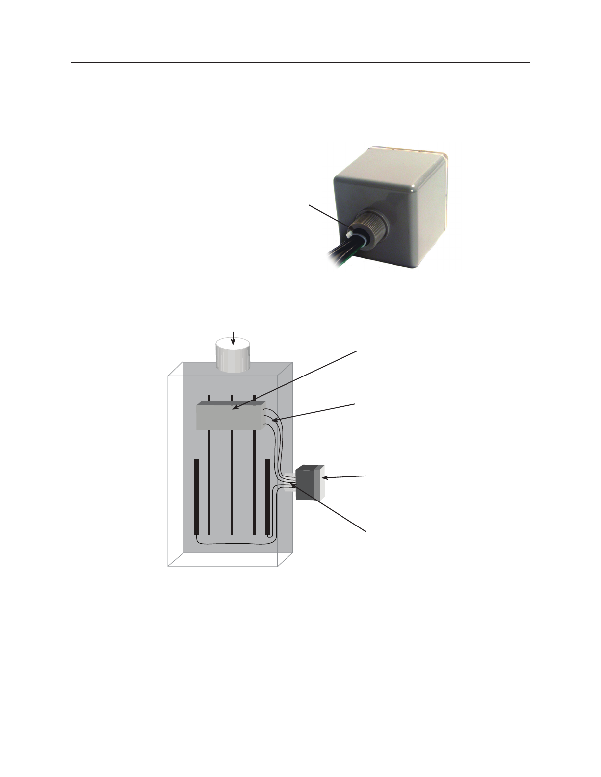
Figure 4: Nipple
A
BC
GN
BREAKER
Sealing gasket:
Two choices
1) At 3/4 in. nom. thread: ID is 1.05 in.
2) At 0.14 in. high 'base step': ID is 1.25 in.
SPD50K
Figure 5: Typical panel Installation
To Protected Loads
(Type 1 or individual equipment
installations may vary)
Use closest breaker to SPD
Locate SPD close to intended
breaker
Keep Leads Short as Possible
Avoid Sharp Bends
Rotate Model SPD50K
such that LED indicator is
most visible
Outdoor installation requires
appropriate weather sealing
at nipple (gasket, sealing
conduit, etc.)
Page: 11

SPD50K
Figure 6: Single-Phase, Three-Wire Installation
Phase A (Black)
v
}
Neutral (White)
}
v
Black
White
Black
Phase B (Black)
Ground (Green)
Figure 7: Three-Phase, Three- or Four-Wire, Grounded WYE Installation
Phase A (Black)
A
N
Phase B (Black)
B
Neutral (White)
Green
Black
Black
White
v
Phase C (Black)
C
Ground (Green)
Black
Green
1
Note 1: The neutral conductor is not present on three-wire Wye grounded power systems.
Figure 8: Three-Phase, Three-Wire, Delta Installation
Black
Black
Black
Green
Page: 12
Phase A (Black)
v
Phase B (Black)
Phase C (Black)
Ground (Green)

Figure 9: Mounting the SPD50K
• 3/4" pipe nipple (conduit nut included)
• With L-bracket mounting kit accessory
- Standard 35mm DIN-Rail (not included)
• L-bracket tightens onto DIN-Rail
- Standard at mounting surface
• Attach L-bracket to surface via mounting holes
SPD50K
Std. 3/4”-14
Nipple
DIN-Rail Mount
(rail not incl.)
Bracket Mount
for at surfaces
Surface-Mount Installation
Note: Mount the unit as close as possible to the protected panel.
1. Make perforations on the wall according to the screw holes located on the enclosure. (Rotate dimensions
90° as appropriate depending on orientation).
2. Congure the electrical conductor and conduit connection consistent with the installation instructions
in this manual.
Page: 13

SPD50K
Operation
DANGER
HAZARD OF ELECTRIC SHOCK, EXPLOSION, OR ARC FLASH
• Apply appropriate personal protective equipment (PPE) and follow safe electrical work practices. See NFPA 70E,
NOM-029-STPS or CSA Z462.
• This equipment must only be installed and serviced by qualied electrical personnel.
• Turn o all power supplying this equipment before working on or inside equipment.
• Always use a properly rated voltage sensing device to conrm power is o.
• Replace all devices, doors and covers before turning on power to this equipment.
• This equipment must be eectively grounded per all applicable codes. Use an equipment-grounding conductor to
connect this equipment to the power system ground.
Failure to follow these instructions will result in death or serious injury.
LED Status Indicators
Diagnostic LEDs are located on the front of the SPD50K device. They operate as follows:
• Verify that all phase voltages are present. If the LED is not illuminated, the device may not be installed
correctly. Check the power supply and service voltage. Upon energizing the SPD, check the LED status. If
LED is illuminated, surge suppression is operating.
• If one LED is illuminated, there is a loss of surge suppression.
• If an inoperative condition occurs the device must be replaced by a qualied electrical personnel.
Figure 10: Diagnostic Operation
Indicator LED is GREEN = OK
Indicator LED OFF = loss of
surge suppression, replace as required.
Page: 14
SPD50K
Dry Contacts
DANGER
HAZARD OF ELECTRIC SHOCK, EXPLOSION, OR ARC FLASH
• Use 600VAC rated dry contact wiring.
• Dry contact wiring must have less than 1/16 in. (1.6mm) exposed wire from the dry contact block.
• Do not supply more than 24VDC / 24VAC and no more than a current of 2 A.
Failure to follow these instructions will result in death or serious injury
This SPD50K device is provided with dry contacts. The unpowered state shall be closed between the common
wire and the normally closed wire. This is also the alarm condition. The opposite state, closed between the
common wire and the normally open wire, indicates that power is on to the unit and that no alarm condition
exists. These dry contact leads can be used for remote indication of the SPD operating status to a computer
interface board or emergency management system.
The dry contacts are designed for a maximum voltage of 24VDC / 24VAC and a maximum current of 2 A.
Higher energy applications may require additional relay implementation outside the SPD. Damage to the
SPD’s relay caused by use with energy levels in excess of those discussed in this instruction bulletin are not
covered by warranty. For application questions, please contact SolaHD Technical Services.
Connecting Optional Form C Dry Contact & Audible Alarm
The dry contacts are designed for a maximum voltage of 24VDC / 24VAC and a maximum current of 2 A.
Higher energy applications may require additional relay implementation outside the SPD. Damage to the
SPD’s relay caused by use with energy levels in excess of those discussed in this instruction bulletin are not
covered by warranty. For application questions, call the SolaHD technical support at 1-800-377-4384 or email
us at solahd.technicalservices@emerson.com.
Three 3 ft. (~1 m) 18 AWG wires are included through the nipple with this option. See Figure 12. Gray is
Common, Blue is Normally Open and Red is Normally Closed when energized in its expected installation.
(When not energized, the SPD is no longer in its ‘Normal’ state and contacts will be reversed.)
If the dry contacts are not utilized, insulate lead ends, coil and secure. Audible Alarm will still
function correctly.
The contact is rated 24VDC / 24VAC and a maximum current of 2 A. Higher energy applications require
supplemental relaying. This option monitors the suppression elements condition and is not intended for use as
phase loss or phase detection monitoring.
Page: 15

SPD50K
Figure 11: Leads
• Normally Closed (suggested): Use Gray and Red
• Normally Open: Use Gray and Blue
Blue
Red
Gray
Preventive Maintenance
DANGER
HAZARD OF ELECTRIC SHOCK, EXPLOSION, OR ARC FLASH
• Apply appropriate personal protective equipment (PPE) and follow safe electrical work practices. See NFPA 70E,
NOM-029-STPS or CSA Z462.
• This equipment must only be installed and serviced by qualied electrical personnel.
• Turn o all power supplying this equipment before working on or inside equipment.
• Always use a properly rated voltage sensing device to conrm power is o.
• Replace all devices, doors and covers before turning on power to this equipment.
• This equipment must be eectively grounded per all applicable codes. Use an equipment-grounding conductor to
connect this equipment to the power system ground.
Failure to follow these instructions will result in death or serious injury.
Inspect the SPD periodically to maintain system performance and continued transient voltage surge
suppression. During this inspection, check the state of the display LED status indicators.
Page: 16

Technical Support
Website: www.solahd.com
Technical Support E-Mail: solahd.technicalservices@emerson.com
Toll-Free: (800) 377-4384
USA: (847) 268-6651
Warranty
Please see the “Terms & Conditions of Sale” document.
SPD50K
While every precaution has been taken to ensure accuracy and completeness in this manual, Appleton Grp LLC d/b/a Appleton Group
assumes no responsibility, and disclaims all liability for damages resulting from use of this information or for any errors or omissions.
Page: 17

SPD50K Series
A272-329 Rev. 2 03/2021
The Emer son logo is a trademark and ser vice mark of Emerson Elect ric Co.
Appleton Grp LLC d/b/a Appleton Group. SolaH D is a registered t rademark of App leton Grp LLC.
All othe r marks are the proper ty of their respec tive owners. © 2021 Emerson Elec tric Co. All rig hts reserved.
United States
(Headquarters)
Appleton Grp LLC
9377 W. Higgins Road
Rosemont, IL 60018
Unite d States
T +1 800 621 1506
Australia Sales Office
Bayswater, Victoria
T +61 3 9721 0387
Korea Sal es Offic e
Seoul
T +82 2 3483 1555
PN# 96 44_rB
Europe
ATX SAS
Espace I ndustriel N ord
35, rue André Durouchez,
CS 980 17
80084 A miens Cedex 2
France
T +33 3 2254 1390
China Sa les Offic e
Shanghai
T +86 21 3338 7000
Canada
EGS Electrical Group Canada
Ltd.
99 Unio n Street
Elmira O N, N3B 3L7
Canada
T +1 888 765 2226
Middle East Sales Office
Dammam, Saudi Arabia
T +966 13 510 3702
Asia Pac ific
EGS Priv ate Ltd.
Block 4 008, Ang Mo Ki o
Ave 10,
#04 -16 TechPlace 1,
Singapore 569625
T +65 6556 1100
Chile Sa les Offi ce
Las Condes
T +56 2928 4819
Latin America
EGS Comercializadora
Mexi co S de RL de CV
Calle 10 N° 145 Piso 3
Col. San P edro de los Pin os
Del. Álvaro Obregon
Ciudad d e México. 01180
T +52 55 5809 5049
India Sales Office
Chennai
T +91 44 3919 7300
 Loading...