

Page 1
GLX250-CEF Cover End Fan Kit
Designed for the following power supplies: GL250 Series
What’s Included
• One cover with end fan
• Four M3 x 6mm countersunk screws
Recommended Assembly
1.Remove M3 x 6mm countersunk screws (4) and original cover.
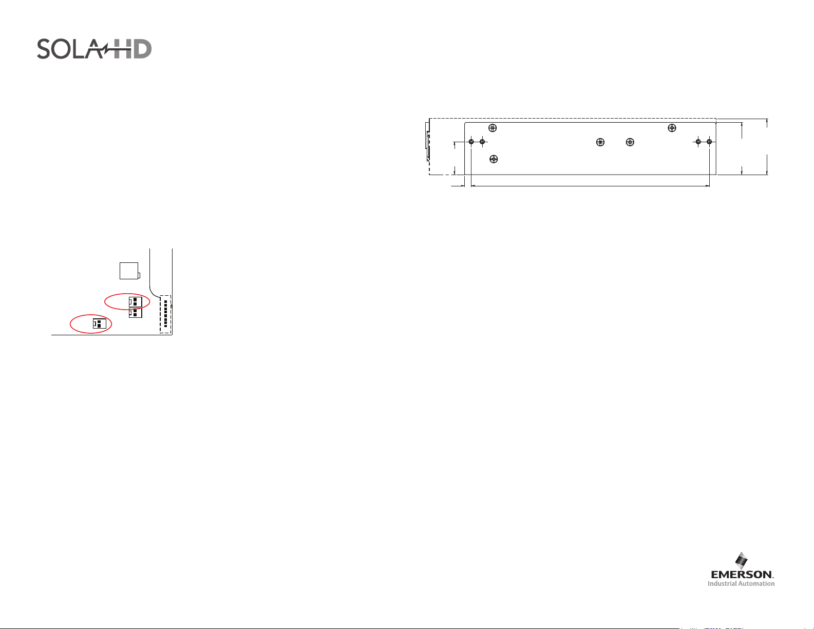
2.Attach the two fan wires to SK4 and SK7 output connectors.
Output Adj.
+
SK4
-
+
SK5
-
SK7
Figure 1: Fan connection
3.Place cover over power supply and align with base countersink holes.
SK3
Overall Dimensions
1.18
[30.0]
8.52 [216.4]
0.24
[6.1]
Figure 2: Mechanical Drawing
1.87
[47.5]
Max
Notes
• All dimensions are in inches [mm].
• Ensure that the relevant safety standards (e.g. EN60950-1) are complied with in
respect to creepage and clearance distances, and distances through insulation.
Technical Support
U.S.: (800) 377-4384 • International: (847) 268-6000
E-mail: [email protected] • Web site: www.solahd.com
2.01
[51.0]
Max
4.Secure cover to base using the supplied M3 x 6mm countersunk screws (4).
While every precaution has been taken to ensure accuracy and completeness in this manual, EGS Electrical Group, LLC. assumes no responsibility, and disclaims all liability for damages resulting from use of this information or for any errors or omissions.
The SolaHD and Emerson logos are registered in the U.S. Patent and Trademark Ofce. All other product or service names are the property of their registered owners. ©2009 EGS Electrical Group, LLC. All rights reserved. Specications subject to change without notice.
P/N: A272-218 Rev 0 12/14/09 Ref: LPX250-CEF
 Loading...