

GLT40 Series, GLT40-M Series Installation & Operating Instructions
M2
M1
Installation & Safety
To comply with the published safety standards, the following must be observed when using
this power supply:
1. Maximum ambient temperature for the power supply must not exceed 50°C.
2. When installing the power supply in the end-use equipment, special attention is
required to ensure safety compliance with the following safety standards: UL60950-1,
EN60950-1, IEC60950-1, and CSA22.2 No. 60950-1-03 for GLT42, GLT43, GLT44,
GLT45, and GLT46; UL60601-1, EN60601-1, IEC60601-1, and CSA22.2 No. 60601-1M90 for GLT42-M and GLT45-M. The safety requirements include creepage distances,
clearances, and distance through insulation between primary wiring and earth or
secondary (SELV) wiring.
3. The power supply’s rated input voltage is automatically selected. Please refer to the
specication sheet for the input voltage range.
4. The maximum output power of the supply must not exceed the rating indicated in the
specication sheet.
5. The earth ground wire must be connected only to the point marked with the earth
ground symbol (on the unit).
6. Hazardous voltages exist in the primary circuits. Disconnect the power supply before
servicing.
7. When operating with a dc input voltage range, the unit input must be protected by a dc
rated fuse in the end-use installation system.
8. The internal fuse should only be replaced with a 2.5 A, 250 V ac, type SP0001.1008
manufactured by Schurter AG or type 21602.5 manufactured by Littelfuse.
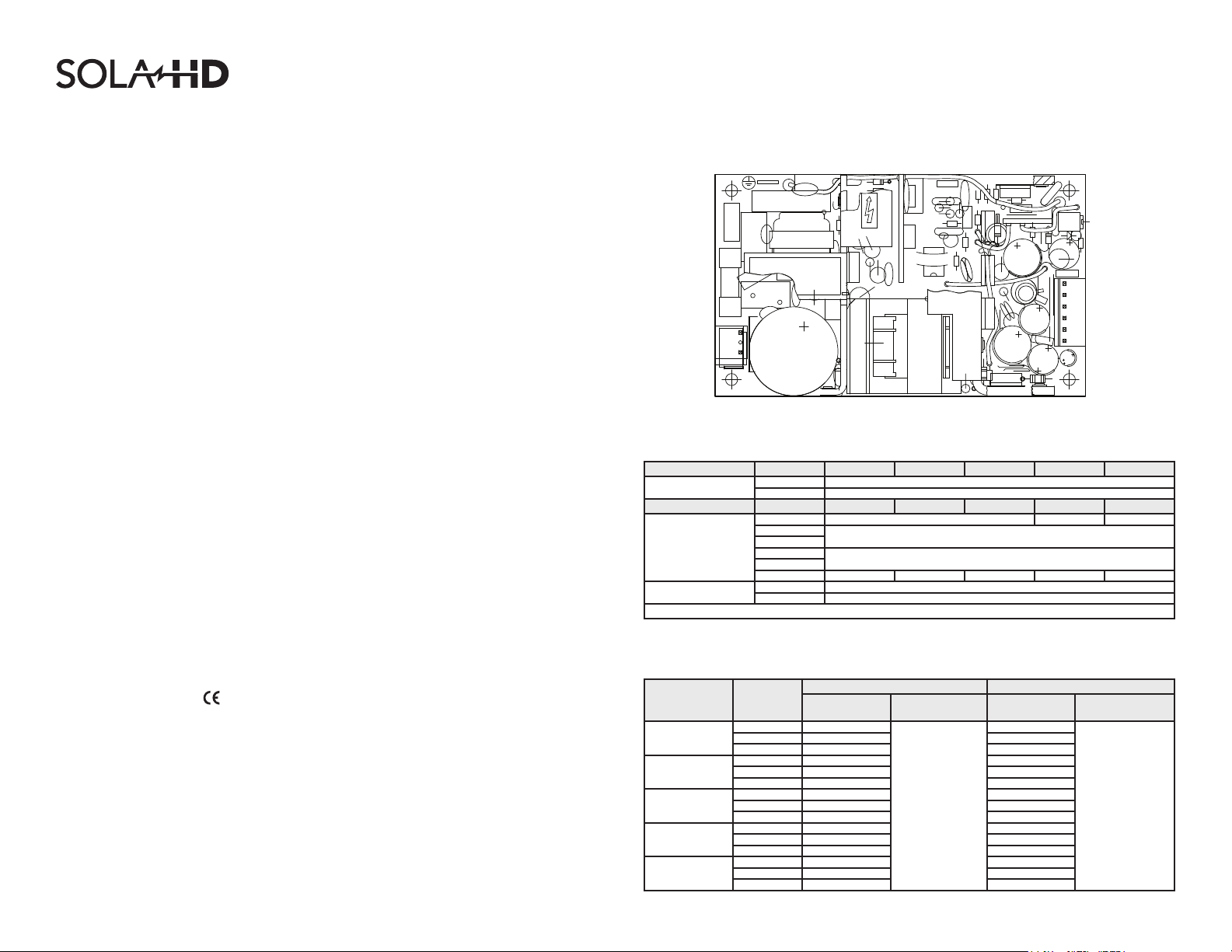
Mechanical Outline
Voltage
Adj. Pot
1
2
3
SK2
4
5
6
SK1
3
1
Connector PIN Designation
InputConnector PIN GLT42(-M) GLT43 GLT44 GLT45(-M) GLT46
SK1
OutputConnector PIN GLT42(-M) GLT43 GLT44 GLT45(-M) GLT46
SK2
SK201
NOTE:Mounting holes M1 and M2 should be grounded for EMI purposes. Mounting hole M1 is an earth ground connection.
1 Line
3 Neutral
1 +12 V +15 V +24 V
2
3
4
5
6 -12 V -12 V -5 V -15 V +12 V
1 +Sense
2 -Sense
+5 V
Common
9. GLT42-M and GLT45-M have no patient applied part.
10. This equipment is considered Class I according to protection against electric shock.
11. This power supply is
2006/95/EC.
marked following the provisions of the Low Voltage Directive,
For technical assistance, contact SolaHD Technical Support at (800) 377- 4384 or send an
e-mail to tech@solahd.com. Please visit our Web site at www.solahd.com for additional
product information and specication sheets.
Model
GLT42(-M)
GLT43
GLT44
GLT45(-M)
GLT46
Output Ratings
Output
Voltage(V)
+5 4.0
+12 2.0 2.5
-12 0.5 0.7
+5 6.0 8.0
+12 0.5 0.7
-12 0.5 0.7
+5 4.0 5.0
+12 2.0 2.5
-5 0.5 0.7
+5 4.0 5.0
+15 2.0 2.5
-15 0.5 0.7
+5 4.0 5.0
+24 1.0 1.5
+12 0.5 0.7
ConvectionCooling 30CFMForcedAirCooling
Max.Output
Current(A)
Max.OutputPower
(W)
40
P/N: A272-181 Rev 1 01/06/10 Ref: 03361001284/03366200501
Max.Output
Current(A)
5.0
Max.OutputPower
(W)
55

GLT40 Series, GLT40-M Series Installation & Operating Instructions
.22 [5.6]
2.55 [64.8]
3.00 [76.2]
.22 [5.6]
Mechanical Dimensions
4.55 [115.6]
5.00 [127.0]
Bottom View
1.08 [27.5] MAX
.15 [3.81]
diameter (4X)
6.69 [170.0]
1.57 [40.0]
4.33 [110.0]
Typical Ventilation Setup
AIR FLOW
FAN
7.28 [185.0] 4.33 [110.0]
Top View
AIR FLOW
FAN
T1
UNIT
UNIT
Side View
.06 [1.6]
All dimensions are in inches [mm]
.12 [3.0] MAX
While every precaution has been taken to ensure accuracy and completeness in this manual, EGS Electrical Group, LLC. assumes no responsibility, and disclaims all liability for damages resulting from use of this information or for any errors or omissions.
The SolaHD and Emerson logos are registered in the U.S. Patent and Trademark Ofce. All other product or service names are the property of their registered owners. ©2009 EGS Electrical Group, LLC. All rights reserved. Specications subject to change without notice.
GLT42, GLT43, GLT44, GLT45, GLT46, GLT42-M, and GLT45-M are commercial designations of model numbers LPT42, LPT43, LPT44, LPT45, LPT46, LPT42-M, and LPT45-M respectively.
Fan: MINEBEA 3110NL-04W-B30
Fan Input: 12 V dc
NOTE: Dimensions and fan used are for reference only
Side View
GLT40, GLT40-M Series Specifications
p
Electrical Specifications
Input
Input ra nge 85-264 Vac; 120-300 Vdc
Frequency 47-440 Hz
Inrush current <18 A peak @ 115 Vac; <36 A peak @ 230 Vac, cold start @ 25°C
Input current 1 A max. (RMS) @ 115 Vac
Efficiency 70% typical at full load
EMI
Safety ground
leakage current
Output
Maximum power 40 W convection; 55 W with 30 CFM forced air
Cross regulation ±2% on output 1; ±5% on outputs 2, 3
Adjustment range -5, +10% minimum
Hold-up time 20 ms @ 40 W load, 115 Vac nominal line
Overload protection
Overvoltage protection 5.7 to 6.7 Vdc on the main output
Minimum Load
Remote sense Compensates for 0.5 V lead drop min. Will operate without remote sense connected. Reverse connection protected.
0.4 A for first output, 0.2 A for second outputs: GLT42, GLT44, GLT45; 0.5 A for the 1st output of GLT43;
FCC Class B conducted; CISPR 22 Class B conducted;
EN55022 Class B conducted; VDE 0878 PT3 Class B conducted
<0.5 mA @ 50/60 Hz, 264 Vac input;
GLT40-M: <75μA @ 50/60 Hz, 264 Vac input
Short circuit protection on all outputs.
Case overload protected @ 110-145% above peak rating
0.4 A for first output, 0.1 A for second outputs: GLT46
Environmental Specifications
Operating temperature
Storage temperature -40°C to 85°C
Temperature coefficient ±.04% per °C
Electromagnetic
susceptibility
Humidity Operating; non-condensing 5% to 95%
Vibration Three orthogonal axes, sweep at 1 oct/min, 5 min. dwell at four major resonances 0.75 G peak 5 Hz to 500 Hz, operational
MTBF demonstrated >550,000 hours at full load and 25°C ambient conditions
Mating Connectors
AC Input
DC Outputs
Remote Sense Molex 22-01-2025; PINS 08-52-0123
Molex 09-50-8031 (USA) Not required for (-T) option; 09-91-0300 (UK)
PINS: 08-52-0113
Molex 09-50-8061 (USA) Not required for (-T) option; 09-91-0600 (UK)
PINS: 08-52-0113
Connector Kit #70-841-006, includes all of the above
1. Specifications subject to change without notice.
2. All dimensions in inches (mm), tolerance is ±0.02” (±0.5mm).
3. Mounting holes M1 and M2 should be grounded for EMI purposes.
4. Mounting hole M1 is safety ground connection.
5. Specifications are for convection rating at factory settings at 115 Vac input, 25°C unless otherwise stated.
6. Warranty: 2 year
7. Weight: 0.5 lb/0.23 kg
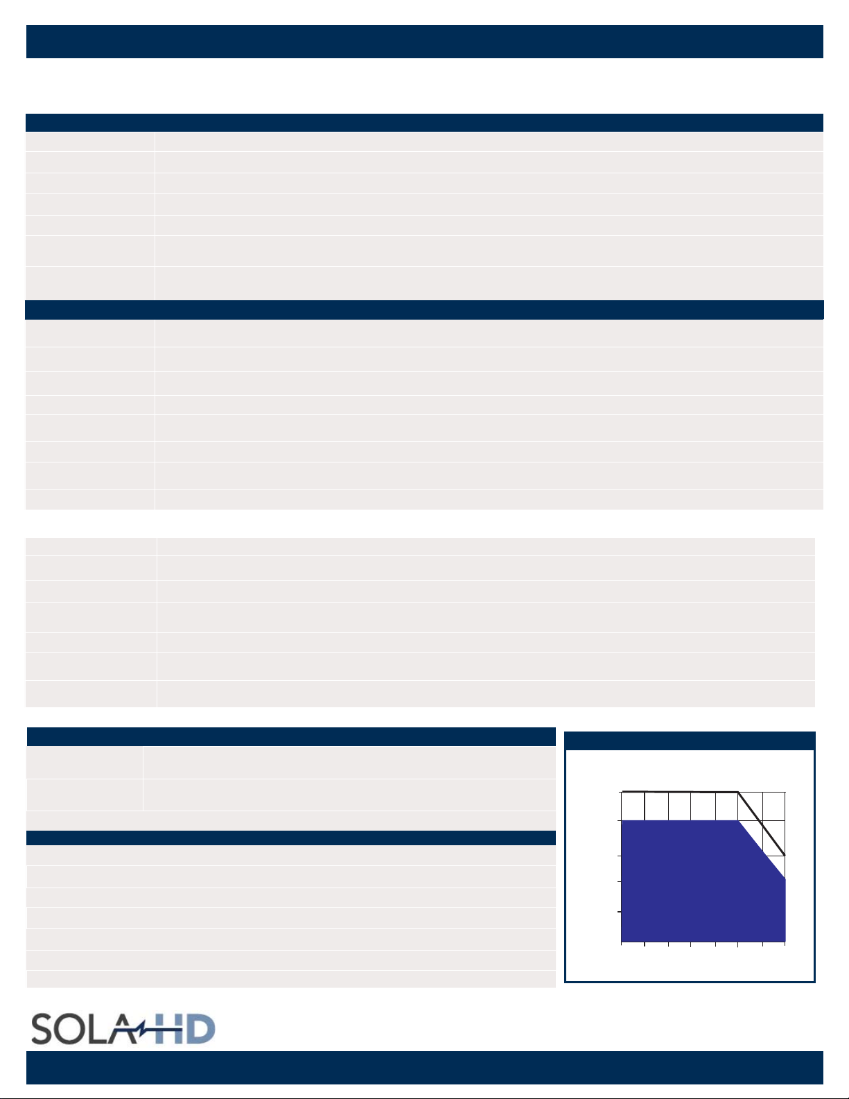
0° to 50°C ambient. Derate each output 2.5% per degree from 50° to 70°C; -20°C start up.
Designed to meet IEC 801, -2, -3, -4, -5, -6, Level 3
Power Derating Curve
Power Derating Curve
30 CFM Forced Air Cooling
Natural
Convection
Cooling
0°C
10°C 20°C 30°C 40°C 50°C 60°C 70°C
TA – Ambient Tem
Output
Power
(Watts)
55W
40W
30W
20W
10W
0W
erature – °C
27.5W
20W
Phone: (800) 377-4384
Email: tech@solahd.com
www.solahd.com
 Loading...