


Solahart PV Systems must be installed and serviced by a suitably qualified person.
Installation Instructions
Single-Phase PV Systems

PATENTS
This PV System may be protected by one or more patents or registered designs in the name of
Solahart Industries Pty Ltd.
TRADE MARKS
™ Trademark of Solahart Industries Pty Ltd.
Note: Every care has been taken to ensure accuracy in preparation of this publication.
No liability can be accepted for any consequences, which may arise as a result of its application.
Warning: For continued safety of this PV System, it must be installed, operated and maintained in
accordance with these instructions and the installation guide supplied with the PV inverter.
Caution: Only qualified and accredited personnel should perform work on PV systems, such as design,
installation, commissioning, maintenance and repairs. Be sure to follow the safety instructions for all system
components. It is also important to observe relevant local codes and regulations for health and safety and
accident prevention.
Only Solahart parts and Solahart approved parts may be used. No substitute parts may be used without
prior approval from Solahart Industries Pty Ltd. Only parts supplied by Solahart Industries Pty Ltd are
covered by the Solahart warranty.
The warranty can become void if safety devices are tampered with or if the installation is not in
accordance with these instructions.

3
CONTENTS
Contents ....................................................................................................................................... 3
Overview ....................................................................................................................................... 4
Wiring Diagrams .......................................................................................................................... 6
Earthing Arrangements – All Systems .................................................................................... 10
Installation Procedure ............................................................................................................... 11
Planning ..................................................................................................................................... 12
Racking ....................................................................................................................................... 17
Rooftop Isolator ......................................................................................................................... 24
Wiring ......................................................................................................................................... 25
Power Optimizers (SolarEdge only) ........................................................................................ 27
PV Modules ................................................................................................................................ 30
Inverter ....................................................................................................................................... 35
Meter (SolarEdge Only) ............................................................................................................. 39
Labelling ..................................................................................................................................... 42
Commissioning .......................................................................................................................... 44
Engineering Certification .......................................................................................................... 51
Solahart PV System Warranty - Australia Only ...................................................................... 53

4
OVERVIEW
The following installation instructions detail installation procedures for photovoltaic modules, power optimizers,
inverter, module racking systems and balance of system (BOS) components.
Prior to the installation of any grid connected PV system, a Site Visit shall be performed in accordance with
the Clean Energy Council’s “Grid-Connected Solar PV Systems - Design Guidelines for Accredited Installers”.
SAFETY REQUIREMENTS
The voltages and currents produced by a single module or modules connected in series (voltages added
together) or in parallel (currents added together) can be dangerous.
Although module DC plug connectors are insulated to provide touch safe protection, the following points must
be observed when handling modules in order to avoid the risk of sparking, fire hazard, burn risk, and lethal
electric shocks:
Exercise extreme caution when wiring modules and look out for damaged or split cable ends.
Do not perform wiring work in rainy or damp conditions.
Never insert metallic or otherwise conductive objects into plugs or sockets.
Ensure that all electrical connections are completely dry and free from contaminants before they are
assembled.
Ensure that connections are tight and correctly made.
Keep all materials, tools and work areas clean and dry.
Always use appropriate safety equipment such as insulated tools and wear personal protective equipment
such as insulated gloves.
Solar modules produce current when exposed to sunlight. It is recommended that the system is shielded
with an opaque cover during installation, maintenance or repair work.
INSTALLER RESPONSIBILITIES
The installer is solely responsible for:
Observing and conforming to all relevant Australian Standards, all relevant Clean Energy Council
Accreditation guidelines and all applicable laws, ordinances, regulations, codes of practice and local or
national building codes, including any that may have superseded these Installation Instructions.
Ensuring that the installation complies with AS/NZS 3000, AS/NZS 5033, AS/NZS 1170.2,
AS/NZS 1562.1, AS 4777.1, AS/NZS 1768, AS/NZS 3008, AS 2050 and any relevant electrical service
and installation rules for the state or territory where the system is installed.
Ensuring that the PV System and associated components are appropriate for the particular installation
and the installation environment.
Ensuring that the roof, roof rafters, battens, purlins, connections, and other structural support members
can support the total assembly under building live load conditions. The roof on which the PV system is to
be installed must have the capacity to resist the combined Design Dead Load and Live Load at each
mounting point.
Ensuring only parts supplied by Solahart Industries and installer supplied parts as specified by Solahart
Industries are utilised (substitution of parts may void the warranty and invalidate certification).
Ensuring that lag screws have adequate pull-out strength and shear capacities to suit the installation.
Maintaining the waterproof integrity of the roof, including selection of appropriate flashing.
Ensuring safe installation of all electrical aspects of the PV system.
OVERVIEW
5
DISCLAIMER OF LIABILITY AND WARRANTY
Solahart assumes no responsibility for loss, damage or expense resulting from improper installation, handling
or misuse of PV modules. Refer to “Solahart PV System Warranty - Australia Only” on page 53 for full warranty
terms and conditions.
IEC 61730 INFORMATION
Modules supplied by Solahart are designed to fulfil the criteria of application Class A requirements according
to IEC 61730. Modules are qualified for application Class A: Hazardous voltage (Higher than 50 V DC) and
hazardous power (higher than 240 W) applications where general contact access is anticipated. For the
purposes of AS/NZS 3000, modules are classified as Class I equipment.
FIRE GUIDELINES
Utilise the following fire safety guidelines when installing modules supplied by Solahart:
Modules supplied by Solahart have a Class C Fire Rating.
Check with local authorities for guidelines and requirements concerning fire safety for any building or
structure on to which the modules will be installed.
The system design should ensure that fire fighting personnel can access the system in the event of a
building fire. Check with local authorities for any applicable regulations concerning setbacks or other
placement restrictions that may apply for roof-mounted PV arrays.
Any electrical equipment can pose a fire risk. Modules must therefore be mounted over a fire retardant
roof covering rated for the application and a distance of 60mm between the module and the mounting
surface must be respected to allow free circulation of air beneath the module.
ENVIRONMENTAL FACTORS
Solahart’s limited warranty is based upon modules being installed in accordance with the following conditions:
Modules are not suitable for installation in potentially hazardous locations.
Modules should not be installed in locations:
near sources of flammable gases, vapours or open flames.
in direct contact with salt water/spray. Avoid installing in areas subject to high salt mist content.
which experience extreme hail and/or snow.
where they may be exposed to sulphur e.g. near sulphur springs or volcanoes
where they may be exposed to harmful chemicals.
WARNINGS
Warning: This document provides sufficient information for system installation heights up to 10 m. If the
installation site is more than 10 m in height contact Solahart Industries for further advice.
Warning: This system has not been certified for, and should not be installed in, wind region D.
Warning: During installation and when working on the roof, be sure to observe the appropriate OH&S safety
regulations and relevant regulations of your local region.
Warning: Ensure electrical connection/ disconnection is performed only when the relevant circuit is isolated.
Do not connect / disconnect wiring under load conditions.
Warning: Do not expose the PV modules to artificially concentrated light.
Warning: Do not drill holes in the modules as this will void product warranty.
6
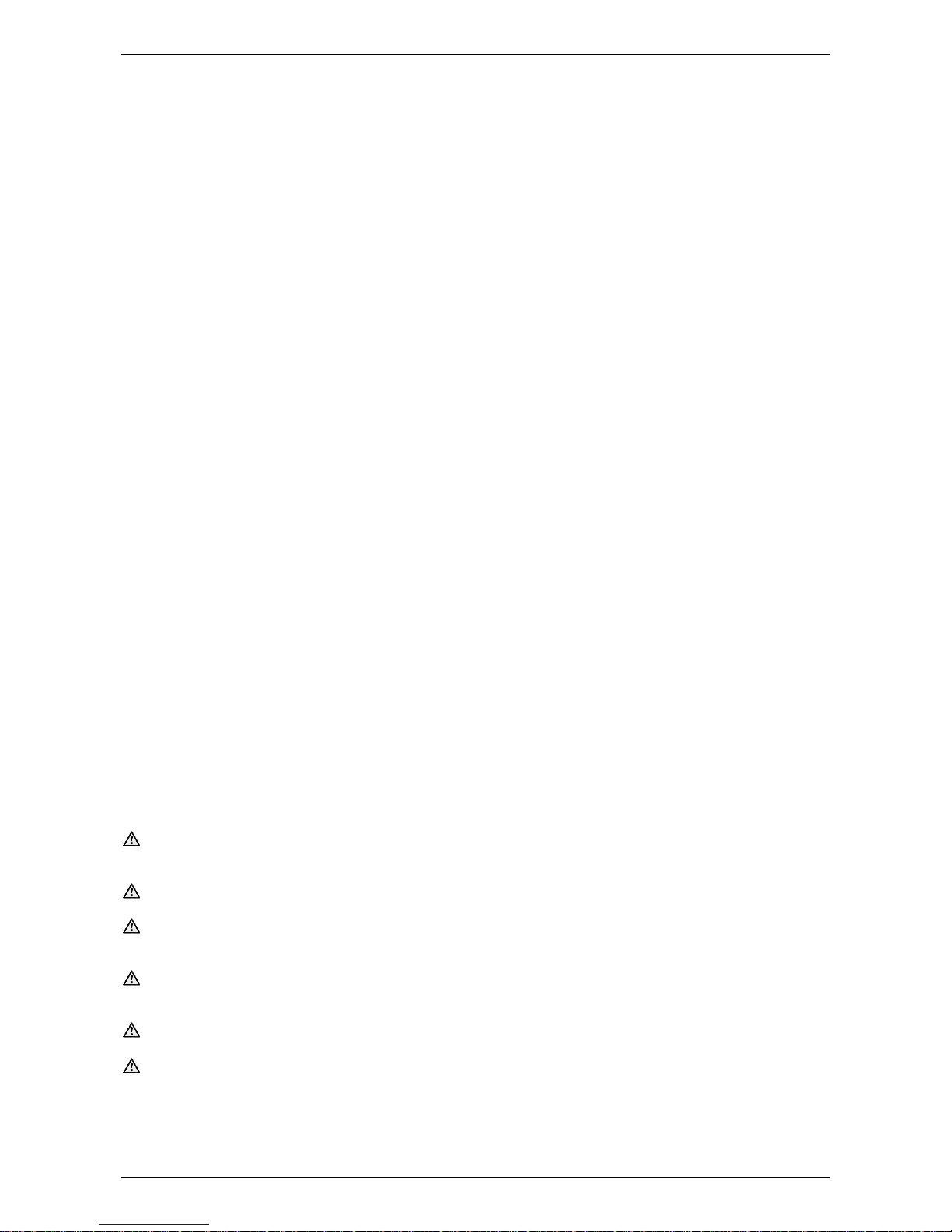
WIRING DIAGRAMS
SINGLE INPUT INVERTER SYSTEMS
For DC Isolator Wiring refer to “DC Isolator Wiring” on page 26.
REC280TP Modules
Inverter
Min No
of
Modules
Max No of
Modules
per String
Max
No of
Strings
Max No
of
Modules
per
Inverter
Max
System
Power
Rating
(W) *
I
sc
(A)*
per
String
V
oc
(V)*
UNO-DM-2.0-TL-PLUS-B
3 8 1 8 2240
9.4
Check
Voltage
Tables on
page 9
SB1.5-1VL-40
3 7 1 7 1960
9.4
SB2.5-1VL-40
3
11 1 11
3080
9.4
REC290TP2 Modules
Inverter
Min No
of
Modules
Max No of
Modules
per String
Max
No of
Strings
Max No
of
Modules
per
Inverter
Max
System
Power
Rating
(W) *
I
sc
(A)*
per
String
V
oc
(V)*
UNO-DM-2.0-TL-PLUS-B
3 8 1 8 2320
9.58
Check
Voltage
Tables on
page 9
SB1.5-1VL-40
3 6 1 6 1740
9.58
SB2.5-1VL-40
3
11 1 11
3190
9.58
* Values measured at standard test conditions (STC) defined as: irradiance of 1000 W/m2, Spectrum AM 1.5
and cell temperature 25ºC. Variations from STC values will affect actual Isc and Voc and should be allowed for.
Note: -10oC used to calculate maximum V. If minimum temperatures are expected to be lower than -10oC,
maximum number of modules must be re-evaluated.
For earthing arrangement and wiring diagram refer to “Earthing Arrangements – All Systems” on page 10.

WIRING DIAGRAMS
7
MULTIPLE INPUT INVERTER SYSTEMS
For DC Isolator Wiring refer to “DC Isolator Wiring” on page 26.
REC280TP Modules
Inverter
Min No
of
Modules
Max No of
Modules
per String
Max
No of
Strings
Max No of
Modules
per
Inverter
Max
System
Power
Rating
(W) *
I
sc
(A)*
per
String
V
oc
(V)*
SB3.0-1AV-40
5
13 2 14
3920
9.4
Check
Voltage
Tables on
page 9
SB4.0-1AV-40
5
13 2 19
5320
9.4
SB5.0-1AV-40
5
13 2 23
6440
9.4
PVI-3.0-TL-OUTD
4
13 2 14
3920
9.4
PVI-4.2-TL-OUTD
4
13 2 20
5600
9.4
PVI-5000-TL-OUTD
4
13 2 21
5880
9.4
UNO-DM-3.3-TL-PLUS-B
4
13 2 15
4200
9.4
UNO-DM-4.0-TL-PLUS-B
4
13 2 19
5320
9.4
UNO-DM-5.0-TL-PLUS-B
4
13 2 23
6440
9.4
REC290TP2 Modules
Inverter
Min No
of
Modules
Max No of
Modules
per String
Max
No of
Strings
Max No of
Modules
per
Inverter
Max
System
Power
Rating
(W) *
I
sc
(A)*
per
String
V
oc
(V)*
SB3.0-1AV-40
5
13 2 13
3770
9.58
Check
Voltage
Tables on
page 9
SB4.0-1AV-40
5
14 2 18
5220
9.58
SB5.0-1AV-40
5
14 2 22
6380
9.58
PVI-3.0-TL-OUTD
4
13 2 13
3770
9.58
PVI-4.2-TL-OUTD
4
14 2 19
5510
9.58
PVI-5000-TL-OUTD
4
14 2 21
6090
9.58
UNO-DM-3.3-TL-PLUS-B
4
14 2 15
4350
9.58
UNO-DM-4.0-TL-PLUS-B
4
14 2 18
5220
9.58
UNO-DM-5.0-TL-PLUS-B
4
14 2 22
6380
9.58

WIRING DIAGRAMS
8
* Values measured at standard test conditions (STC) defined as: irradiance of 1000 W/m2, Spectrum AM 1.5
and cell temperature 25ºC. Variations from STC values will affect actual Isc and Voc and should be allowed for.
Note: -10oC used to calculate maximum V. If minimum temperatures are expected to be lower than -10oC,
maximum number of modules must be re-evaluated.
For earthing arrangement and wiring diagram refer to “Earthing Arrangements – All Systems” on page 10.
SE5000 INVERTER SYSTEMS
For DC Isolator Wiring refer to “DC Isolator Wiring” on page 26.
REC280TP Modules
Inverter
Min No
of
Modules
Max No of
Modules
per String
Max
No of
Strings
Max No of
Modules
per
Inverter
Max System
Power Rating
(W) *
Max
Inverter
Current
(A)*
Max
Inverter
Voltage
(V)*
SE5000
SE5000-xxxxxxx **
8
18 2 23
6440
19.5
500
SE5000H
8
20 2 23
6440
13.5
480
REC290TP2 Modules
Inverter
Min No
of
Modules
Max No of
Modules
per String
Max
No of
Strings
Max No of
Modules
per
Inverter
Max System
Power Rating
(W) *
Max
Inverter
Current
(A)*
Max
Inverter
Voltage
(V)*
SE5000
SE5000-xxxxxxx **
8
18 2 22
6380
19.5
500
SE5000H
8
19 2 22
6380
13.5
480

WIRING DIAGRAMS
9
* Values measured at standard test conditions (STC) defined as: irradiance of 1000 W/m2, Spectrum AM 1.5
and cell temperature 25ºC. Variations from STC values will affect actual Isc and Voc and should be allowed for.
** This model may have suffixes indicating different options and functionality.
Note: -10oC used to calculate maximum V. If minimum temperatures are expected to be lower than -10oC,
maximum number of modules must be re-evaluated.
For earthing arrangement and wiring diagram refer to “Earthing Arrangements – All Systems” on page 10.
VOLTAGE TABLES FOR SMA AND ABB SYSTEMS
Voc of REC280TP = 39.2V
REC280TP
No of Modules per String
Voc of the String
No of Modules per String
Voc of the String
3
117.6
9
352.8
4
156.8
10
392
5
196
11
431.2
6
235.2
12
470.4
7
274.4
13
509.6
8
313.6
Voc of REC290TP2 = 38.8V
REC290TP2
No of Modules
per String
Voc of the
String
No of Modules per
String
Voc of the
String
3
116.4
9
349.2
4
155.2
10
388
5
194
11
426.8
6
232.8
12
465.6
7
271.6
13
504.4
8
310.4
14
543.2
VOLTAGE TABLES FOR SOLAREDGE SYSTEMS
Note: SolarEdge Inverters operate on a fixed string voltage. The V
oc
of the string is fixed to the nominal DC
voltage of the inverter regardless of the panel Voc.
Voc of REC280TP = 39.2V
Voc of REC290TP2 = 38.8V
Inverter Model
Nominal DC Voltage
Voc of string
SE5000
350 Vdc
350 Vdc
SE5000-xxxxxxxxx *
400 Vdc
400 Vdc
SE5000H
380 Vdc
380 Vdc
* This model may have suffixes indicating different options and functionality.

10
EARTHING ARRANGEMENTS – ALL SYSTEMS
Earthing connections must be made so the removal of one component (e.g. a module) does not interrupt the
earthing to other parts of a system (e.g. other modules). Daisy chaining is not permitted. The PV system earth
connection must be directly connected to the switchboard earth link, not via the inverter earth connection. If
the earth cable could be exposed to direct sunlight, it must have a physical barrier to protect the earth cable
from this exposure.
Earth wires must be sized in accordance with requirements set out in Earthing and bonding arrangements of
AS/NZS 5033.
Solahart approved earthing plates may be used to earth modules via the racking, instead of wiring directly to
the module frames. Refer to “Earthing” on page 31 for more information.
Warning: Do not drill holes in the modules as this will void product warranty.
The racking may be earthed by means of a rooftop isolator bracket. Refer to “Rooftop Isolator” on page 24 for
details.
Where it is necessary to make an earthing connection to a rail that does not have a rooftop isolator bracket
fitted, a rail splice piece will provide a suitable surface for connection. In this case, the splice should be attached
to the end of the rail using both fixing bolts, and then the earth lug connected to the splice as shown in the
figures below:
1. Slide rail splice onto end of rail, ensuring an overhang of approximately 50 mm.
2. Secure rail splice by tightening both Allen head bolts to 15 Nm.
3. Drill a hole in the centre of the rail splice, attach the earth cable using the earthing set supplied, and tighten
to 5 Nm.
Rail splice attached to rail with both Allen head bolts
Earth cable connected to splice

11
INSTALLATION PROCEDURE
1. Planning – Design the system and layout. Refer to “Planning” on page 12.
2. Determine the spacing of the Rail Supports using the “Maximum Rail Support Spacing Tables” on page
18 and considering the following factors (refer to “Planning” on page 12):
a. Wind Region
b. Terrain Category
c. Roof Type
d. Roof Area
e. Building Height
f. Array Orientation
3. Install the Racking (Rail and Rail Supports). Refer to “Racking” on page 17.
4. Install the remainder of the roof top components as follows:
a. Rooftop Isolator. Refer to “Rooftop Isolator” on page 24.
b. Rooftop Wiring. Refer to “Wiring” on page 25.
c. Power Optimizers. Refer to “Power Optimizers (SolarEdge only)” on page 27.
d. PV modules. Refer to “PV Modules” on page 30.
5. Install the inverter. Refer to “Inverter” on page 35.
6. Install the energy meter (optional component). Refer to “Meter (SolarEdge Only)” on page 39.
7. Install the system labels. Refer to “Labelling” on page 42.
8. Commission the PV system. Refer to “Commissioning” on page 44.

12
PLANNING
INSTALLATION TOOLS
4,5 & 6 mm Allen keys or 4,5 & 6 mm Allen Key fittings to suit torque adjustable drill (for racking
components and inverter)
Torx T20 screwdriver (ABB inverter systems only)
Cordless torque adjustable drill
Angle grinder with stone disk (for tile cutting if required)
Electricians hand tools (screwdrivers, pliers etc.)
String line
Timber to shim tile roof interfaces (if required)
STRUCTURAL ASSESSMENT
The installer is responsible for ensuring that the building and building structures are capable of withstanding
the additional loads and forces generated as a result of installing the PV system. For domestic dwellings, it is
recommended that a structural engineering assessment is completed. For all other installations, a structural
assessment is required to be completed by a qualified structural engineer.
COMMUNICATIONS DEVICES
Complete installation of inverter communications devices requires the installer to register the communication
device and inverter on the inverter manufacturer’s web portal. Hence, to complete the communications
equipment installation, the installer must have access to the PV system owner’s internet connection. An
example of items that should be organised prior to onsite installation are:
Confirmation that an internet accessible network port is available
Length of networking cable required from inverter to networking port
Wi-Fi access including SSID and password
PV system owner’s network administrator permission and assistance to adjust firewall, network
address translation (NAT) and port forwarding settings.
PV MODULE ORIENTATION AND INCLINATION
To maximize system output, install modules at optimum orientation and inclination (tilt) angles. The specifics
of this will depend on the installation location and must be calculated by a qualified system designer. The ideal
angle for mounting a module should result in the sun’s rays falling perpendicular (i.e. at a 90° angle) to the
module surface.
Note: All modules in each series string must have the same orientation and inclination to ensure that modules
do not underperform due to a mismatching of each module’s output.
Modules should be installed in a shade free position. Even minor or partial
shading of the modules/array will reduce array/system output. A module is
considered shade free when it is both:
Free from shade or shadows all year round.
Exposed to several hours of direct sunlight, even during the
shortest days of the year.
Note: The following information is provided as a guide only:
Modules should be installed facing toward true north. Where this
orientation is not practical, a system facing up to 45° (NW or NE)
from true north is satisfactory however losses of up to
approximately 6% will occur. A module facing due east or due
west will experience a loss in performance of approximately 18%.
Inclination of modules should be approximately equal to the local latitude angle. The latitude of some
Australian cities is shown in the “Latitude of Some Australian Cities” on page 13. Modules may be

PLANNING
13
installed at the roof angle for simplicity of installation and appearance, however, if inclination varies by
±15º or more from the correct inclination, performance losses of 4% or more will occur.
Modules should be inclined at an angle of at least 10° to support the self-cleaning function of the
glass.
Losses for incorrect orientation and incorrect inclination will be compounded.
If the roof angle is flat, adjustable or fixed tilt legs should be considered to optimise inclination
depending upon area.
For an installation at right angles to (across) a tile roof pitch, landscape tile roof hooks are required.
Each module and its fittings including racking weighs approximately 25 kg.
LATITUDE OF SOME AUSTRALIAN CITIES
Adelaide
35°S
Cairns
17°S
Hobart
42°S
Port Hedland
20°S
Alice Springs
24°S
Canberra
35°S
Mildura
34°S
Rockhampton
24°S
Brisbane
27°S
Darwin
12°S
Melbourne
38°S
Sydney
34°S
Broken Hill
31°S
Geraldton
28°S
Perth
32°S
Townsville
19°S
WIND REGION
Use the wind region diagram shown below to determine the wind region of the installation site.
Wind region notes:
Wind regions are predefined for all of Australia by Australian Standard AS/NZS 1170.2. The Wind
Region has nothing to do with surrounding topography or buildings.
Most of Australia is designated Region A which indicates a Regional Ultimate Basic Wind Velocity of
45 m/s.
Some areas are designated Region B (57 m/s). Local authorities will advise if this applies in your
area.
Region C areas (66 m/s) are generally referred to as Cyclonic and are generally limited to northern
coastal areas. Most Region C zones end 100 km inland.
Region D (80 m/s) Australia's worst Cyclonic Region between Carnarvon and Pardoo in WA.

PLANNING
14
TERRAIN CATEGORY
The terrain over which the approaching wind flows towards a structure must be assessed on the basis of the
following category descriptions:
Terrain Category 2: Open terrain, including grassland, with well-scattered obstructions having heights
generally from 1.5 m to 5 m, with no more than two obstructions per hectare, e.g. farmland and cleared
subdivisions with isolated trees and uncut grass.
Terrain Category 3: Terrain with numerous closely spaced obstructions having heights generally from 3 m to
10 m. The minimum density of obstructions shall be at least the equivalent of 10 house-size obstructions per
hectare, e.g. suburban housing or light industrial estates.
ROOF TYPE
Determine the roof type of the building where the PV modules are to be installed and select the appropriate
rail support.
Rail support systems are available as follows:
Roof Type
Roof Pitch
Rail Support Category
Rail Support Name (Options)
Standard tile
10 - 30º
Tile roof interface
Tile interface (Portrait)
Tile interface (Landscape)
Low profile tile
Flat tile interface
Slate
Slate interface
Metal
10 - 30º
Metal roof interface
Metal roof interface
Metal
Corrugated
< 10 º
or
< Latitude minus 15º
Tilt leg interface
10 - 15° adjustable tilt legs
15 - 30° adjustable tilt legs
30° fixed tilt legs
30 - 60° adjustable tilt legs
ROOF AREA
Determine the installation area on the roof (roof position area). The diagrams below show roof position areas
designated as “Edge Zone” areas and “Centre Zone” areas according to interface type.
Edge zone areas are subject to higher wind loadings and therefore will require closer rail support spacing.
Warning: If any part of the system array is located in one of the edge zones, the entire array must use the
support spacing specified for the edge zones.
PLANNING
15
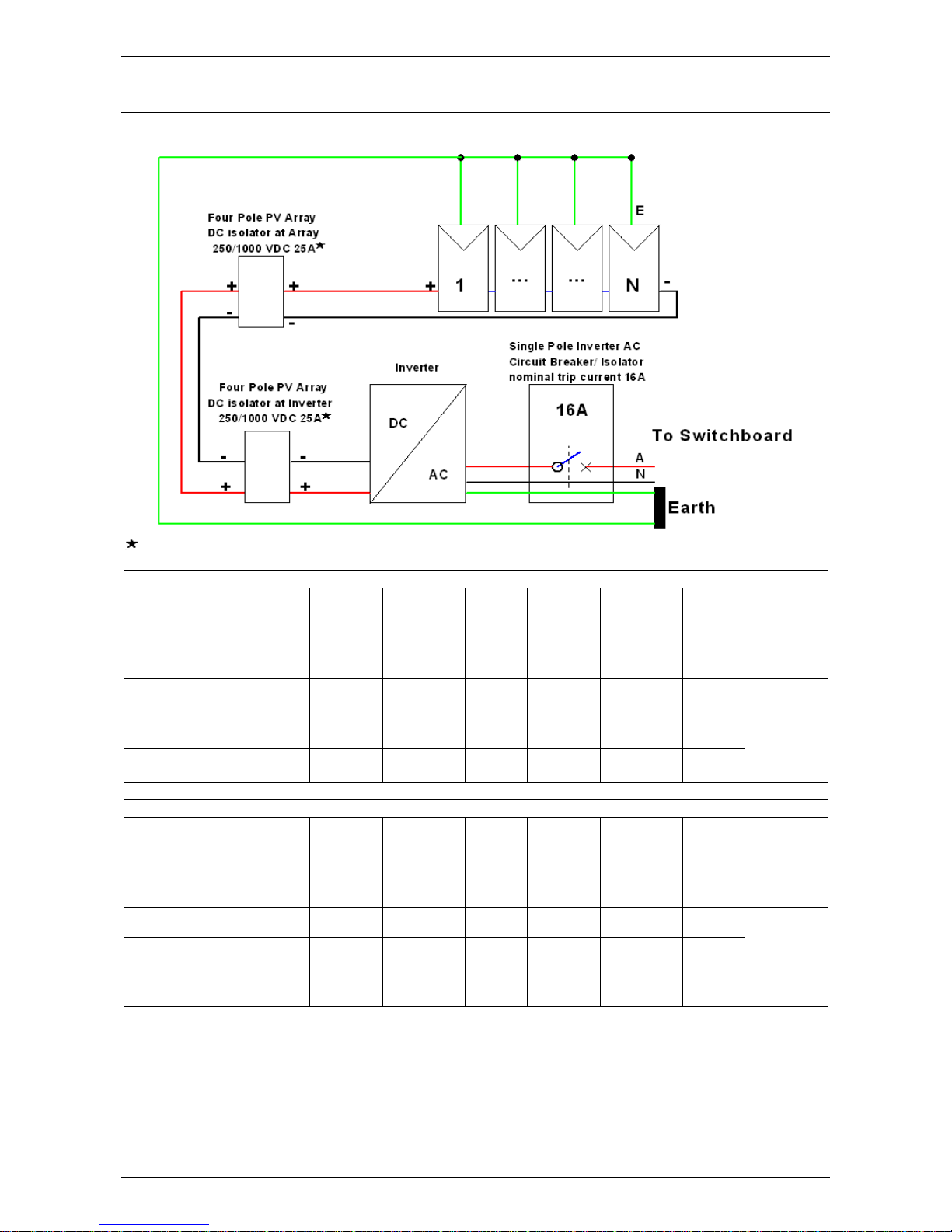
Use the following diagram, tables and worked example to determine the minimum required roof area for
the array when designing and installing with REC280TP modules.
REC280TP spacing and dimensions
Worked Example:
Number of rows: 2
Number of modules per row: 10
Total number of modules = 20
Calculating H:
H=N
rows
×(1,665+20
)
-20
H=2×1,685-20
H=3,350 mm
Calculating W:
W=
N
modules/row
×(991+18)+(2×25
)
-18
W=10×1,009+50-18
W=10,122 mm
Calculating Area
Roof
in mm2:
Area
Roof
=H×W
Area
Roof
=3,350×10,122
Area
Roof
=33,908,700 mm
2
Converting Area
Roof
in mm2 to m2:
Area
Roof
=
33,908,700
1,000,000
=33.91 m
2
Calculating Area
Roof
in m2:
Area
Roof
=
H
1,000
×
W
1,000
Area
Roof
=
3,350
1,000
×
10,122
1,000
Area
Roof
=3.35×10.122
Area
Roof
=33.91 m
2
Notes:
Modules installed in portrait as per diagram
For tilt leg systems, row spacing must prevent shading of one row by another and needs to be calculated on
an individual site basis, taking into account orientation, roof pitch and module inclination
All dimensions are in mm, unless otherwise stated.
Number of modules per row – REC280TP
1 2 3 4 5 6 7 8 9 10
…
Number of rows
H 1665
1665
1665
1665
1665
1665
1665
1665
1665
1665
1 X X X X X X X X X X X W 1041
2050
3059
4068
5077
6086
7095
8104
9113
10122
H 3350
3350
3350
3350
3350
3350
3350
3350
3350
3350
2 X X X X X X X X X X X W
1041
2050
3059
4068
5077
6086
7095
8104
9113
10122
…
Number of modules per row – REC280TP
1 2 3 4 5 6 7 8 9 10
…
Number of rows
Roof 1
Area
1.73
3.41
5.09
6.77
8.45
10.13
11.81
13.49
15.17
16.85
(m2)
Roof
2
Area
3.49
6.87
10.25
13.63
17.01
20.39
23.77
27.15
30.53
33.91
(m2)
…

PLANNING
16
Use the following diagram, tables and worked example to determine the minimum required roof area for
the array when designing and installing with REC290TP2 modules.
REC290TP2 spacing and dimensions
Worked Example:
Number of rows: 2
Number of modules per row: 10
Total number of modules = 20
Calculating H:
H=N
rows
×(1,675+20
)
-20
H=2×1,695-20
H=3,370 mm
Calculating W:
W=
N
modules/row
×(997+18)+(2×25
)
-18
W=10×1,015+50-18
W=10,182 mm
Calculating Area
Roof
in mm2:
Area
Roof
=H×W
Area
Roof
=3,370×10,182
Area
Roof
=34,313,340 mm
2
Converting Area
Roof
in mm2 to m2:
Area
Roof
=
34,313,340
1,000,000
=34.31 m
2
Calculating Area
Roof
in m2:
Area
Roof
=
H
1,000
×
W
1,000
Area
Roof
=
3,370
1,000
×
10,182
1,000
Area
Roof
=3.37×10.182
Area
Roof
=34.31 m
2
Notes:
Modules installed in portrait as per diagram
For tilt leg systems, row spacing must prevent shading of one row by another and needs to be calculated on
an individual site basis, taking into account orientation, roof pitch and module inclination
All dimensions are in mm, unless otherwise stated.
Number of modules per row – REC290TP2
1 2 3 4 5 6 7 8 9 10
…
Number of rows
H 1675
1675
1675
1675
1675
1675
1675
1675
1675
1675
1 X X X X X X X X X X X
W 1047
2062
3077
4092
5107
6122
7137
8152
9167
10182
H 3370
3370
3370
3350
3370
3370
3370
3370
3370
3370
2 X X X X X X X X X X X W 1047
2062
3077
4092
5107
6122
7137
8152
9167
10182
…
Number of modules per row – REC290TP2
1 2 3 4 5 6 7 8 9 10
…
Number of rows
Roof
1
Area
1.75
3.415
5.15
6.85
8.55
10.25
11.95
13.65
15.35
17.05
(m2)
Roof 2
Area
3.53
6.95
10.37
13.79
17.21
20.63
24.05
27.47
30.89
34.31
(m2)
…

17
RACKING
OVERVIEW OF RACKING COMPONENTS
Overview of components for tile roof
Rail
(a)
Rail splices
(c)
Tile roof
Interfaces (b)
Z-modules with
Allen head bolt
Wood screws M6
x 80
Overview of components for metal roof
Rail
(a)
Rail splices
(c)
Metal roof
interfaces (b)
Z-modules with
Allen head bolt
Wood screws M6
x 90 *
Overview of components for adjustable tilt legs
Rail
(a)
Rail splices
(c)
Z-modules with
Allen head bolt
Front rail &
leg foot (d)
Adjustable
tilt leg (e)
Wood Screws
M6x90 *
Overview of components for 30º fixed tilt legs
Rail
(a)
Rail splice
(c)
Z-modules with
Allen head bolts
Front rail &
leg foot (d)
Fixed
tilt leg (e)
Wood Screws
M6x90 *
* Note: Screws must be fit for purpose e.g. screws used in metal purlins must be suitable for metal structures
and have a TPI (threads per inch) of 14.
Tile & Metal Roof Diagram (Tile Roof shown)
Tilt Leg Diagram (Adjustable Tilt Leg shown)
Rail Support Spacing
Rail Support Spacing
Rail
Spacing
Rail
Spacing
Rail Overhang

RACKING
18
RAIL SUPPORT SPACING
Use the following tables to determine the rail support spacing for the relevant roof type based on the previously
determined wind region, terrain category, roof position area (Edge Zone or Centre Zone) and maximum height
of the installation.
MAXIMUM RAIL SUPPORT SPACING TABLES
Wind Region A
Terrain Category 2 3
Roof Area
Edge Zone
Centre Zone
Edge Zone
Centre Zone
Roof Height (m)
5
10 5 10 5 10 5 10
Tile Roof (Timber Rafters only)
1200
950
1575
1275
1475
1800
Metal Roof with Timber Battens
1505
1247
1700
1600
1675
1800
Metal Roof with Steel Battens
1075
890
1523
1261
1432
1800
Tilt Legs – PV Module Angle 15°
1325
1025
1500
1254
1400
1575
Tilt Legs – PV Module Angle 30°
1089
902
1400
1350
1325
1500
Wind Region B
Terrain Category 2 3
Roof Area
Edge Zone
Centre Zone
Edge Zone
Centre Zone
Roof Height (m)
5
10 5 10 5 10 5 10
Tile Roof (Timber Rafters only)
825
675
1100
875
1025
1350
Metal Roof with Timber Battens
938
777
1329
1101
1250
1759
Metal Roof with Steel Battens
670
555
949
786
893
1265
Tilt Legs – PV Module Angle 15°
927
768
944
782
1235
1257
Tilt Legs – PV Module Angle 30°
679
562
1078
892
904
1435
Wind Region C
Terrain Category 2 3
Roof Area
Edge Zone
Centre Zone
Edge Zone
Centre Zone
Roof Height (m)
5
10 5 10 5 10 5 10
Tile Roof (Timber Rafters only)
525
450
700
575
650
850
Metal Roof with Timber Battens
582
526
825
745
910
735
1289
1042
Metal Roof with Steel Battens
416
375
589
532
650
525
921
744
Tilt Legs – PV Module Angle 15°
576
520
586
529
850
727
915
740
Tilt Legs – PV Module Angle 30°
421
380
669
604
658
532
1045
845
Roof interfaces must be fixed to rafters or purlins under the roof cladding. Screw minimum embedment into
timber rafters is 50 mm and 35 mm for timber battens.
Steel purlins must meet the following minimum requirements:
Roof interface
Minimum steel purlin specification
Metal roof interface
0.55 mm BMT 550 Grade or 0.75 mm BMT 450 Grade
Tilt leg interface
1.0 mm BMT 500 Grade
Note: Screws supplied with the roof interfaces are wood screws suitable for timber only. Screws used in metal
purlins must be suitable for metal structures and have a TPI (threads per inch) of 14.

RACKING
19
RAIL SPACING
Rails should be spaced so that the module is clamped in the correct positions.
In general, the rails may be spaced between 833 mm and 1249 mm apart for REC280TP modules and 843 mm
and 1259 mm apart for REC290TP2 modules.
RAIL OVERHANG
Rail end overhang must be no greater than 50% of rail support spacing. For example; if rail support spacing is
1200 mm, rail end overhang can be up to 600 mm. In this case, two rail support brackets can support a rail up
to 2400 mm in length (1200 mm between brackets and 600 mm of overhang at each end).
Note: Drawings not to scale
Rail Spacing:
REC280TP: 833 – 1249 mm
REC290TP2: 843 – 1259 mm
Rail Support
Spacing = x
Rail Overhang < x/2

RACKING
20
TILE ROOF INSTALLATION
Note: The tile roof interface is only suitable for installation on timber rafters.
1. Determine and mark the position of the
tile roof interfaces according to your
plans. Remove the roof tiles at marked
positions or, if possible, simply move the
tiles up slightly.
2. Fix the tile roof interfaces to rafters
using two M6 X 80 mm wood screws.
Ensure a 50 mm minimum screw
embedment into the rafters.
3. Warning: Tile roof interfaces must not
press against roof tiles and must be
fixed parallel with rafters. If necessary,
pack underneath tile roof interfaces with
timber.
Incorrect
Correct
4. Warning: Do not use tile roof interfaces
as a climbing support as extreme
loading of this point could cause
damage to the tile below.
5. For thin tiles (such as slate, shingles)
proceed directly to step 6.
For thick tiles (such as grooved tiles), if
necessary, use an angle grinder to
chase a recess (or remove raised
groves) on the tile that covers the tile
roof interface at the point where the
interface protrudes through so that the
tile lies flat.
For thick tiles it may also be necessary
to cut a recess into the tile located below
the tile roof interface.
Now proceed to installation of the rails.
Refer to “Rail Installation” on page 23.

RACKING
21
6. For thin tiles (such as slate, shingles), a
portion of tile must be cut and removed
from the tile above the tile roof interface,
creating a recess.
Suitable flashing must then be installed
around the tile roof interface, with an
overlap of at least 150mm at the edges
of the recess.
Now proceed to installation of the rails.
Refer to “Rail Installation” on page 23.
METAL ROOF INSTALLATION
Note: Screws supplied with the roof interfaces are wood screws suitable for timber only. Screws used in metal
purlins must be suitable for metal structures and have a TPI (threads per inch) of 14.
1. Determine and mark position of the metal roof
interfaces according to your plans. Pre drill
through roof cladding (on top of crest) at planned
locations. Place the supplied rubber gasket under
the metal roof interface and ensure that a
weatherproof seal is made between the interface
and the roof cladding.
2. Fix the metal roof interface to the timber batten or
rafter using the M6 x 90 mm screw supplied.
Ensure a 50 mm minimum screw embedment for
rafters or 35 mm for timber battens.
If the interface is being fixed to metal purlins use
screws suitable for metal structures with a TPI of
14.
3. Check the metal roof interface to ensure that the
fastening screw tightly fixes sealing gasket
without damaging roof cladding.
Now proceed to installation of the rails. Refer to
“Rail Installation” on page .

RACKING
22
TILT LEG INSTALLATION
Note: Screws supplied with the tilt legs are wood screws suitable for timber only. Screws used in metal purlins
must be suitable for metal structures and have a TPI (threads per inch) of 14.
1. Determine and mark position of feet according
to your plans. Pre drill through roof cladding (on
top of crest) at planned locations. Place the
supplied rubber gaskets under each foot and
ensure that a weatherproof seal is made
between the foot and the roof cladding.
2. Fix the foot to the timber batter or rafter using a
minimum of two M6 X 80 mm screws.
Ensure a minimum screw embedment of
35 mm for timber battens and 50 mm for rafters.
If the interface is being fixed to metal purlins
use screws suitable for metal structures with a
TPI of 14.
Check the foot to ensure that the fastening
screws tightly fix the sealing gaskets without
damaging roof cladding.
Adjustable tilt leg foot
30º fixed tilt leg foot
3. Adjustable tilt legs only: Insert feet U
brackets into front feet and loosely fasten Allen
head bolt and nut to allow for later adjustment.
Allen head bolt and Z-module on top of U
bracket is utilised to attach rails in next step.
4. For adjustable tilt legs: Place rear legs into
feet, insert Allen head bolt, washer, retaining
washer and nut and fasten loosely to allow for
later adjustment.
For 30º fixed tilt legs: Place rear legs onto
feet, insert Allen head bolt, washer, retaining
washer and nut and tighten to 15-20 Nm.
Adjustable tilt legs
30º fixed tilt legs
5. Loosen the leg telescopic section Allen head
grub screws. Adjust the leg length according to
your plans and tighten the grub screws to
17 Nm.
6. Fix the leg L bracket to the leg using the Allen
head bolt, washer, retaining washer and nut
and fasten loosely to allow for later adjustment.

RACKING
23
RAIL INSTALLATION
1. Install rails onto the roof interfaces. If the
assembly consists of rails of different
lengths, always begin with the shortest
piece. Install the rail loosely onto the roof
interfaces using the Allen head bolt,
washer, retaining washer and Z-modules
supplied (2 to 3 turns of the bolt are
adequate for loose installation). Refer to
step 2 for method of inserting Z-module
into rail.
2. For easy use of Z-modules ensure that
Allen head bolt threads do not project
through lower side of Z-module so that
the Z-module is free to move. Position Zmodules in rail channel as shown and
fasten loosely with 2 to 3 turns of Zmodule Allen head bolt. The rail can then
be freely moved along Z-modules.
3. Adjust the vertical and horizontal position
of the rail by taking advantage of the long
hole in the tile and metal roof interfaces
and the still loose connection of the rail
Z-modules.
4. Align all rail ends.
For adjustable tilt legs: align the rail tilt
orientation (use a string line if
necessary).
Tighten all previously loosely installed
rail and feet Z-module Allen head bolts to
a torque of 21 Nm.
5. To connect multiple rails together, slide
a splice on to the rear side of the
previously assembled rail. Tighten the
first splice Allen head bolt to 15 Nm.
Slide the next rail segment into the
splice. An expansion gap at the rail joints
is recommended. Leave a gap of
approximately 10 mm between the rail
joints and then tighten the second Allen
head bolt to 15 Nm.

24
ROOFTOP ISOLATOR
When installing the rooftop DC isolator, a Solahart Rooftop Isolator Subassembly must be used and must be
mounted to the rail by following the steps below. To help prevent UV degradation, the Rooftop Isolator
Subassembly should be mounted as far from the north side of the array as possible.
When installing the rooftop isolator the following points should be observed:
Ensure the IP rating of the isolator enclosure is maintained and that no moisture can enter. The conduit
entry points must be on the lower end of the enclosure (i.e.: facing downwards) so that any water will run
away from and not towards enclosure entry points. Screw cover caps must be installed and all mounting
holes should be sealed with silicone to help prevent water ingress.
Cable glands and conduit adapters must be chosen to suit the type of cable or conduit used. E.g. cable
glands designed for figure-8 cables must be chosen where figure-8 type solar DC cables are utilised.
Any conduit adapters should be installed so that the conduit slopes downwards from the enclosure to
prevent water ingress in adverse weather conditions.
If water and/or condensation can form in the isolator enclosure, provision must be made for its harmless
escape through suitably located drainage points in accordance with AS/NZS 3000 Clause 3.3.2.3. Conduit
entering the isolator enclosure must have a drainage hole installed at the lowest point to facilitate the
escape of any moisture.
Note: Install Rooftop Isolator Subassembly before installing any PV modules.
1. Determine where the Rooftop Isolator
Subassembly is to be attached.
a. The Rooftop Isolator Subassembly is
configured for installation on the array as
shown above.
b. If the Subassembly is to be fitted in the other
orientation, move the cover (with the Solahart
logo) from position A to position B as shown
above.
c. If in doubt, slide the subassembly into the rail at
the point of attachment (see Step 4) and check
whether the Solahart logo is facing up.
2. Identify the earth connection point on the bracket,
as shown above.
3. Connect the earthing wire to the connection point,
as shown above, using a tightening torque of
5 Nm.
4. Slide the subassembly into the rail making sure
that the Solahart logo is facing up (see Step 1)
5. Tighten both M8 bolts to 15 Nm, ensuring good
connection between the bolts and rail.

25
WIRING
WIRING
Only UV-resistant cables and connectors approved for outside use should be used. PV cable must be marked
or labelled in accordance with AS/NZS 5033.
To minimise the risk of indirect lightning strikes, avoid forming closed loops when designing the system. Check
to ensure that system wiring is correct before commissioning modules. If the measured open circuit voltage
(Voc) and short circuit current (Isc) differ from specifications, a wiring fault may be present.
Recommended cable size for plug connectors is 4 – 6 mm2, with an operating temperature range of -40 to
+120ºC. Plug connectors are polarised and should be firmly connected. All connections should be secure, tight
and electrically and mechanically sound. Correct DC polarity should be observed at all times. Plug connectors
should never be used to turn the system on or off (i.e. do not connect or disconnect plug connectors under
load conditions).
Only use plug connectors supplied with your Solahart PV system, or which are the same type/model and from
the same manufacturer as those on the PV module. Ensure that all plug connectors and plug wiring are in
good electrical and mechanical condition and are not subjected to mechanical stress.
Ensure that all materials meet system requirements such as maximum voltage, current, moisture and
temperature when exposed to sunlight.
Electrical ratings of the PV modules are within 3% of measured values at Standard Test Conditions (STC).
Under normal conditions, a photovoltaic module may experience conditions that produce more current and/or
voltage than that reported under STC. When designing a system, allow for increased output of a module as a
result of conditions different to STC in accordance with the Clean Energy Council’s “Grid-Connected Solar PV
System - Design Guidelines for Accredited Installers” and AS/NZS 5033.
Ensure cables are fixed to the mounting structure and are not in contact with the roof or rear surface of
module(s) by using restraining devices which are sunlight and UV-resistant.
Note: Plastic cable ties are not to be used as primary means of support.
A roof flashing such as a Dektite® must be used where wiring penetrates tile or metal
roofing. Flashings must be sealed using an appropriate waterproofing compound such
as silicone.
All wiring must be protected from mechanical damage and external wiring must be
protected from UV and mechanical damage in such a manner that it will last the life
of the system. All conduits shall comply with AS/NZS 2053.1 and if exposed to sunlight
must be suitably UV rated and marked with the letter “T”. Do not install wiring such
that it is subject to permanent tension.
COMPONENT PLUG AND DC CABLE SIZING TABLE
Cabling
Plug
Cable Size
Plug Rating
Module fly leads
Pre crimped on fly leads
4 mm2
IP67
Module DC extension leads
Supplied in BOS Kit
Min 4 mm2
IP67
Wiring – Roof isolator to inverter isolator
(a)
Not required – hard wired
Min 4 mm2
N/A
Wiring – Inverter isolator to inverter
(b)
Supplied in BOS Kit for
ABB and SolarEdge inverters or as
supplied with SMA inverters.
Min 4 mm2
IP67
(a)
= DC cable supplied by installer.
(b)
= DC cable supplied by installer for SMA inverters only.
All cables/wiring are double insulated Solar DC type cable.
It is recommended the maximum voltage drop between the PV array and the inverter is 3%.
Dektite

WIRING
26
DC ISOLATOR WIRING
The DC isolators utilised in Solahart PV Systems are not polarity sensitive (non polarised type) however for
uniformity they should be wired as shown in the DC isolator wiring diagram below.
Warning: DC isolator terminal screws must be tightened by hand only. Do not use power tools.
DC isolator wiring
diagram
Once wired, the DC isolator should be left in the open position until system commissioning.

27
POWER OPTIMIZERS (SOLAREDGE ONLY)
Warning: Input and output connectors are not watertight until mated. Open connectors should be mated to
each other or plugged with appropriate watertight caps.
Warning: Cutting the power optimizer input or output cables is prohibited and will void product warranty.
Warning: Do not connect / disconnect DC connectors or wiring while under load.
Warning: Only connectors of the same make and model may be connected together.
Note: Modules with SolarEdge power optimizers output a low safety voltage before the inverter is turned ON.
As long as the power optimizers are not connected to the inverter or the inverter is turned OFF, each power
optimizer will output a safe voltage of 1V (±0.1V).
MOUNTING THE POWER OPTIMIZERS
1. Determine and mark the power optimizer mounting locations on the rail:
a. Power optimizers should be spaced approximately 1009 mm (for REC280TP) or 1015mm (for
REC290TP2) apart on the rail. See figure below.
b. Power optimizers must be positioned so that they maintain a 25 mm clearance distance
between the power optimizer and other surfaces to allow for heat dissipation.
Note: Figure is not to scale.
Note: Ensure clearance between power optimizers and PV module junction boxes.
REC280TP: 1009 mm
REC290TP2: 1015 mm
REC280TP: 1009 mm
REC290TP2: 1015 mm

POWER OPTIMIZERS (SOLAREDGE ONLY)
28
2. Attach each power optimizer to the mounting rail using the Z-module assembly provided in the BOS kit.
See figure below. Apply a tightening torque of 9.5 Nm.
Z-module assembly
Note: It is recommended that the power optimizers be placed face down to ensure clearance between the
back of modules and power optimizers. See figure below.
Note: Figure is not to scale.
3. Verify that each power optimizer is securely attached to the rail.
4. Record power optimizer serial numbers and locations. This can be achieved through the use of a paper
template or SolarEdge smartphone application. Refer to SolarEdge supplied documentation for more
information.
POWER OPTIMIZER WIRING PROCEDURE
Warning: Use insulated tools and wear appropriate PPE when performing wiring to prevent the risk of
electric shock.
PV Module and power optimizer DC plug connectors are connected as follows:
Firmly push positive (+) plug into negative (-) plug until an audible
“click” is heard, and then try to pull plugs apart. Incorrectly connected
plugs will come apart whilst correctly connected plugs will not come
apart unless the locking latches on either side of the positive (+) plug
are depressed using an unlocking tool whilst plugs are pulled apart.
Note: Pull on plugs, do not pull on wiring.
+ -
Warning: Do not connect / disconnect DC connectors or wiring while under load.
Warning: Only connectors of the same make and model may be connected together.
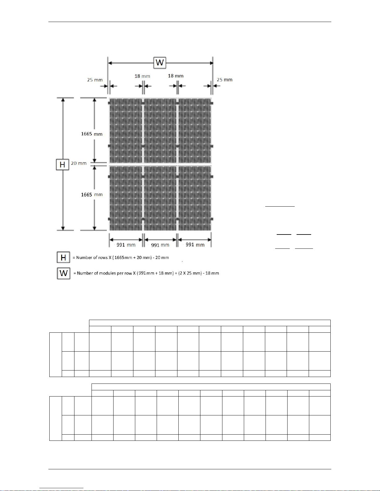
The following procedure should be adhered to whilst wiring power optimizer strings to prevent the risk of electric
shock or inadvertent short circuiting of live cables whilst wiring the Rooftop DC Isolator:
1. Two extension leads per string should be constructed using the DC extension cable provided in the BOS
Kit. One should be short to connect from the first power optimizer in the string to the DC isolator. The other
should be sufficiently long to plug the end power optimizer in the string to the DC isolator (see the example
schematic below).
POWER OPTIMIZERS (SOLAREDGE ONLY)
29
2. Ensure the Rooftop DC Isolator is in the OFF position, strip 12 mm of insulation from the end of each
extension lead and connect the two extension leads to the Rooftop DC Isolator terminals. The Rooftop
DC Isolator should be wired in a consistent manner. Refer to “DC Isolator Wiring” on page 26.
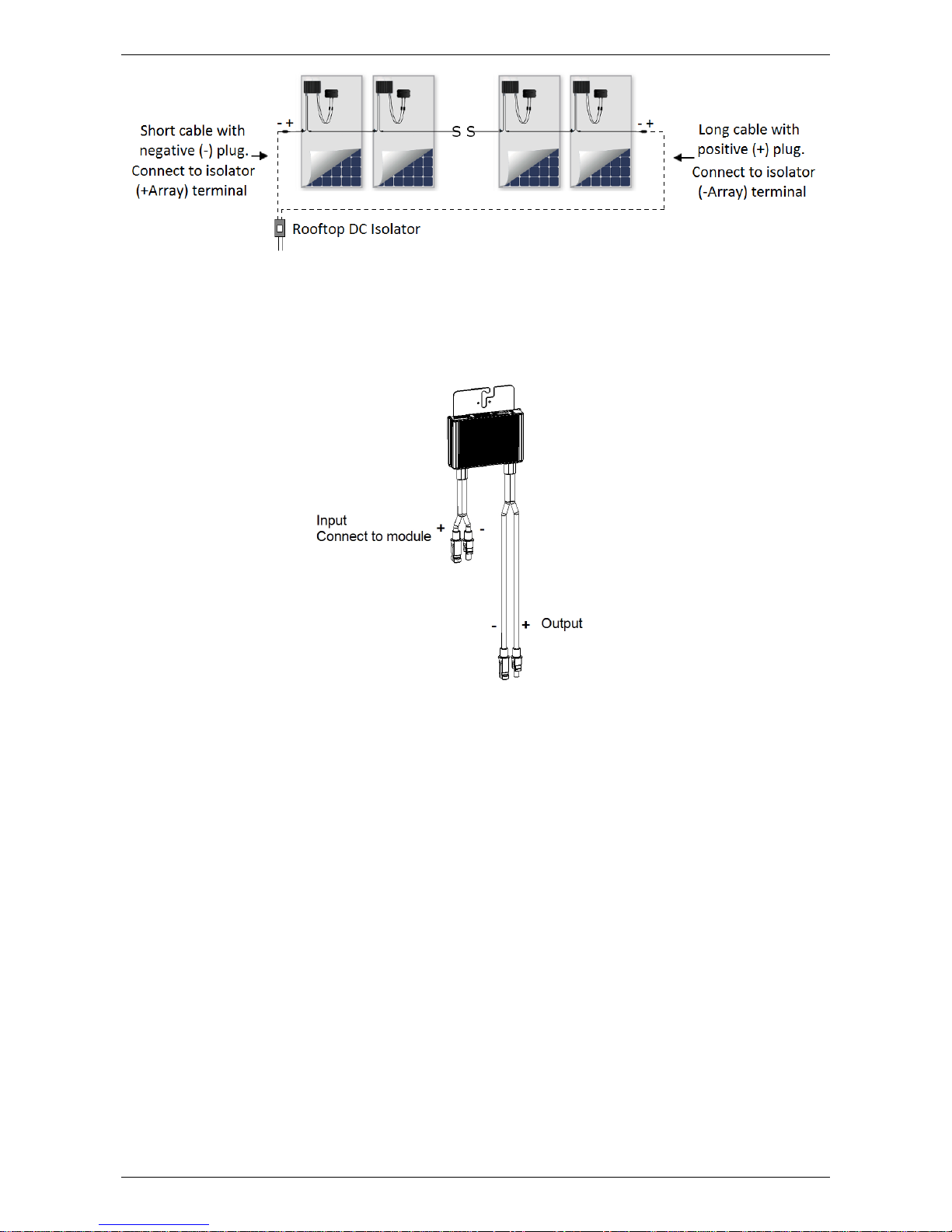
3. Connect the first power optimizer’s positive output (+) cable plug to the Rooftop DC Isolator extension
cable negative (-) plug. See figure below for power optimizer cable plug illustration.
Note: Image is for illustration purposes only. Refer to the label on the product to identify the plus and
minus input and output connectors.
4. Connect each power optimizer’s negative output (-) cable to the following power optimizer’s positive output
(+) cable.
5. Connect the last power optimizer’s negative output (-) cable to the Rooftop DC Isolator extension cable
positive (+) plug.
6. Connect the first power optimizer’s input connectors to the first module’s connectors.
7. Repeat Step 6 for each module and power optimizer in the string.
8. Verify proper power optimizer connection by measuring the voltage of each string individually.
Note: Each power optimizer in the string will output a safe voltage of 1 V (±0.1 V). For example: 9 power
optimizers connected in a single string should output a safe voltage of 9 V (±0.9 V).
Note: Ensure the modules are exposed to sunlight during this process; otherwise, the power optimizers may
not be powered.
9. Repeat Steps 1 - 8 for each string in the PV array.
10. Your PV array wiring is now complete.
Note: The Rooftop DC Isolator should still be in the OFF position at the completion of this stage of the
installation. It should not be turned ON until the correct stage of commissioning. Refer to “Solar Isolation
Device(s) Test – Rooftop DC Isolator(s)” on page 45.

30
PV MODULES
PV MODULES
PV modules generate electricity as soon as they are exposed to sunlight and as such they can represent a
danger. All warnings in this manual must be observed when handling solar modules to avoid the risk of fire,
sparking and/or electrocution.
If modules are connected in series (summing voltage) the combined voltage must not exceed the inverter’s
maximum input voltage rating. For the maximum number of series connected modules permissible, refer to
the relevant wiring diagram in this document for the inverter model installed.
The Solahart mounting system requires the use of modules of equal thickness for correct clamping.
Note: Ensure only modules of the same type (model & thickness) are clamped side-by-side and electrically
connected.
MODULE HANDLING
Modules should be handled with care and protected from damage at all times. All warnings and instructions
on the packaging should be observed. Follow these guidelines when unpacking, transporting or storing the
modules:
Note module serial numbers before installation and record serial numbers in the system documentation.
Carry modules using both hands and do not use the junction box or electrical wiring as a grip.
Do not subject modules or backsheets to loads or stresses.
Do not stand on the modules.
Do not use modules that have been dropped.
Keep all electrical contacts clean and dry.
Store modules in a dry and properly ventilated room.
Do not use sharp or pointed objects to mark module surface or module anodising.
Never apply paints, adhesives, or detergents to the rear laminate of the modules.
Never attempt to disassemble modules, modify or adapt the modules or labels in any way as this will
void the warranty.
Do not drill additional holes in any part of the module. Drilling holes voids the product warranty.
Warning: Do not use modules which are broken or damaged. If the module front glass is broken or laminate
back sheet is damaged in any way, hazardous voltages may be exposed.
STRING WIRING PROCEDURE
Note: If you have completed the “Power Optimizer Wiring Procedure” on page 28, proceed to “Earthing” on
page 31.
Warning: Use insulated tools and wear PPE when performing wiring to prevent the risk of electric shock.
It is suggested that modules be covered with an opaque material during wiring to reduce the voltage generated
by the string.
PV Module DC plug connectors are connected as follows:
Firmly push positive (+) plug into negative (-) plug until an audible
“click” is heard, and then try to pull plugs apart. Incorrectly connected
plugs will come apart whilst correctly connected plugs will not come
apart unless the locking latches on either side of the positive (+) plug
are depressed using an unlocking tool whilst plugs are pulled apart.
Note: Pull on plugs, do not pull on wiring.
+
-
Warning: Do not connect / disconnect DC connectors or wiring while under load.
Warning: Only connectors of the same make and model may be connected together.

PV MODULES
31
The following procedure should be adhered to whilst wiring module strings to prevent the risk of electric shock
or inadvertent short circuiting of live cables whilst wiring the Rooftop DC Isolator:
1. Two extension leads per string should be constructed using the DC extension cable provided in the BOS
Kit. One should be short to connect from the first module in the string to the DC isolator. The other should
be sufficiently long to plug the end module in the string to the DC isolator (see the example schematic
below).
2. Ensure the Rooftop DC Isolator is in the OFF position, strip 12 mm of insulation from the end of each
extension lead and connect the two extension leads to the Rooftop DC Isolator terminals. The Rooftop
DC Isolator should be wired in a consistent manner. Refer to “DC Isolator Wiring” on page 26.
3. Connect the first module positive (+) cable plug to the Rooftop DC Isolator extension cable negative (-)
plug.
4. Connect each module’s negative (-) cable to the following module’s positive (+) cable as modules are
being installed until the halfway point is reached i.e. fourth module in an eight module string.
5. Install and connect the remaining modules, but do not make the halfway connection, i.e. in an eight module
string do not connect the fourth module negative (-) cable to the fifth module positive (+) cable (refer to
wiring diagram below). These two cables will be connected at the end of this procedure.
6. Connect the last module’s negative (-) cable to the Rooftop DC Isolator extension cable positive (+) plug.
7. Complete the circuit by connecting the two string halves together by connecting the positive (+) and
negative (-) cables of the two modules left previously disconnected in step 5.
Note: Modules may be connected in a different order provided that all modules in a string are connected in
series.
Note: The Rooftop DC Isolator should still be in the OFF position at the completion of this stage of the
installation. It should not be turned ON until the correct stage of commissioning. Refer to “Solar Isolation
Device(s) Test – Rooftop DC Isolator(s)” on page 45.
EARTHING
All modules and rails must be earthed. Refer to “Earthing Arrangements – All Systems” on page 10. Earthing
connections must be made by a suitably qualified person according to the relevant standards outlined on page
4. It is also recommended that a reliable lightning protection system be installed.
`Stainless steel serrated washers must be used so the rail anodising is pierced, providing good electrical
continuity. Stainless steel nuts, bolts and washers must be used and all ferrous metal in conductive
connections should be specially treated to prevent corrosion (i.e. by spray painting or coating with a galvanising
paint). Refer also to “Earthing Arrangements – All Systems” on page 10.
Earthing plates
To earth modules and rails, use earthing plates supplied when mounting modules. Install earthing plates in
accordance with the following instructions. When installed correctly, earthing plates will provide earth bond
continuity between rails and modules whilst allowing removal of a module without affecting the earthing
integrity of other components in the system. The rails must then be earthed by connecting a suitably sized
earth wire. Refer to “Earthing Arrangements – All Systems” on page 10.

PV MODULES
32
Warning: Only Solahart approved earthing plates are to be used.
Warning: Module frames must be located on top of earthing plate earth bond protrusions.
Warning: Earthing plates are intended for single use only and must not be reused.
Warning: If rails are not of a continuous length, or rail splices do not provide satisfactory earth continuity,
earth bond jumper cables must be used across rails or rail splices or each section of rail must have an earth
wire connection.
MODULE MOUNTING
Ensure a minimum clearance of 60 mm between the outer surface of the roof and any part of the module to
allow sufficient airflow beneath the modules and adequate cooling of the modules.
Module cables must be installed so that any water will run away from the junction box.
Each corner of the module frame has small drainage holes to allow water caused by rain or snow melt to exit
the frame easily and to minimize damage caused by freezing and thawing. Please note:
The drainage holes must not be used for mounting the module.
Ensure the drainage holes are clear at all times.
Fastening the modules to the mounting structure
Each module must be securely fixed to the mounting structure at a minimum of four points. The distance
between the end clamp and the end of the rail should be a minimum of 25 mm. The mounting clamps must be
fastened so the clamp lies completely within the range of shown below for each type of module.
Note: Figure is not to scale

PV MODULES
33
Module Mounting Procedure
1. Mid clamps and end clamps can be
inserted into the rail by following the
procedure shown, making sure the
spring washer is correctly in place.
For easy use of Z-modules, ensure
Allen head bolt threads do not project
through lower side of Z-module, so the
Z-module is free to move along the rail.
2. In positions where earthing plates are
required, slide the earthing plate over
threaded section of Allen head bolt and
press earthing plate into rail so that rail
retention tabs hold the earthing plate in
position.
3. Install PV module under end clamps.
Ensure end clamps are tight against the
module and are at least 25 mm from the
rail ends. For end clamps with earthing
plates, ensure the frame of the module
is located on top of the protrusions of
the earthing plate. Tighten end clamp
bolts to 21 Nm.
4. Place a mid clamp with Z-module and
Allen head bolt in each rail and slide
into position. Ensure that the mid clamp
is tight against the module. For mid
clamps with earthing plates, ensure the
frame of the module is located on top of
the protrusions of the earthing plate.
Fasten loosely (approx 2 – 3 turns).
5. Place the next module onto the rail and
slide the module into the mid clamps. In
positions where earthing plates are
required, ensure both module frame
edges are located on top of the
protrusions of the earthing plate
6. Tighten each mid clamp Allen head bolt
to 21 Nm.
Repeat steps 4 to 6 for each remaining
module in the row.

PV MODULES
34
7. Place an end clamp into the end of each
rail. Ensure that the end clamps are
tight against the module and are at
least 25 mm from the rail ends. In
positions where earthing plates are
required, ensure the frame of module is
located on top of the protrusions of the
earthing plate. Tighten end clamp bolts
to 21 Nm.
8. Repeat the steps 3 - 7 for each row of
modules.
Mid clamps may be temporarily placed
between rows to ensure 18 mm uniform
spacing between rows.
Module installation is now complete.

35
INVERTER
For inverter installation instructions and warranty exclusions refer to the documents supplied with the inverter.
The following points must also be observed when installing the inverter:
Warning: Inverters have masses between 9 kg and 27 kg. Proper safe handling procedures must be
employed when installing or handling these inverters.
Inverters must be sheltered from direct sunlight and other sources of heat.
Inverters must be installed in a well-ventilated place so as to allow good circulation of air around the
unit. Avoid places where air cannot circulate freely around the unit.
The inverter must not be installed in a location accessible to children.
The mounting structure must be capable of supporting the inverter weight.
If the inverter is to be mounted on a combustible surface such as wood, a heat resistant backing (such
as a fibre cement board) must be installed behind the inverter. Backing must extend a minimum of
20 mm past all edges and sides of the inverter.
Inverter mounting clearances and requirements outlined in the relevant inverter documentation must
be adhered to. Ignoring recommended mounting instructions can cause permanent damage to the
inverter from water ingress and can reduce inverter efficiency due to inadequate heat dissapation..
Sealing plugs provided with the inverter must be inserted into any unused string inputs to maintain the
inverter’s IP rating. For SMA inverters, sealing plugs must inserted into the rear of the Sunclix DC plug
connectors. For ABB and SolarEdge inverters verify the presence of watertight rubber cap seals on
DC input connectors and install them should they be absent.
For the ABB PVI single phase inverters ensure that:
o For multiple string systems, the inverter is configured for ‘independent’ channels (factory
default setting).
o For single string systems, the inverter is configured for ‘parallel’ channels. Refer to inverter
documentation for detailed instructions on configuration of channels.
When installing an inverter with a StorEdge Connection Unit, do not install fuses if a battery is not
installed. Leave all fuses in their original packaging behind the plastic cover inside the StorEdge
Connection Unit, clear from all electrical wires and components.
MULTI-CONTACT DC CONNECTIONS
Multi-Contact Safety Locking Clips must be installed over the negative connectors of all Multi-Contact DC
connections at the inverter. The purpose of these devices is to prevent accidental disconnection of live DC at
the inverter. When the Safety Locking Clip is in place, a custom tool is required to separate the connectors.
Multi-Contact (MC)
Positive (+) Connector: PV-KBT4
Multi-Contact (MC)
Negative (-) Connector: PV-KST4
Multi-Contact (MC)
Safety Locking Clip: PV-SSH4
AC CABLE SIZING TABLE
Inverter AC cabling must be sized and installed in accordance with AS/NZS 3000, AS/NZS 3008 and any
local applicable codes. Cables selected must have an appropriate current carrying capacity for the maximum
fault current output of the inverter, and the Inverter AC isolator, taking into consideration relevant de-rating
factors. For the nominal trip current of the AC breaker, refer to the “Wiring Diagrams” beginning on page 6.

INVERTER
36
Inverter
Model
Maximum AC Fault Current (A)
SB 1.5-1 VL-40
12.0
UNO-DM-2.0-TL-PLUS-B
12.0
SB 2.5-1 VL-40
19.0
PVI-3.0-TL-OUTD
16.0
SB3.0-1AV-40
29.0
UNO-DM-3.3-TL-PLUS-B
16.0
SB4.0-1AV-40
29.0
UNO-DM-4.0-TL-PLUS-B
19.0
PVI-4.2-TL-OUTD
22.0
PVI-5000-TL-OUTD
32.0
SB5.0-1AV-40
29.0
UNO-DM-5.0-TL-PLUS-B
24.0
SE5000-xxxxxxxxx*
27.0
SE5000H
23.0
*This model may have suffixes indicating different options and functionality.
Inverter AC cabling must have a voltage drop or rise less than 1% in accordance with AS/NZS 5033. For
common PVC/PVC cable types operating at 75°C on a 230 V single-phase circuit, the following table provides
for a voltage variation of less than 1%.
Inverter Model
Conductor cross section
2.5 mm2
4.0 mm2
6.0 mm2
10.0 mm2
16.0 mm2
Maximum cable length (m)
SB 1.5-1 VL-40
18.3
29.3
N/A
N/A
N/A
UNO-DM-2.0-TL-PLUS-B
Refer ABB Quick Installation Guide
SB 2.5-1 VL-40
11.6
18.6
N/A
N/A
N/A
PVI-3.0-TL-OUTD
Refer ABB Quick Installation Guide
SB3.0-1AV-40
9.8
15.8
23.5
39.6
N/A
UNO-DM-3.3-TL-PLUS-B
Refer ABB Quick Installation Guide
SB4.0-1AV-40
7.4
11.8
17.6
29.6
N/A
UNO-DM-4.0-TL-PLUS-B
Refer ABB Quick Installation Guide
PVI-4.2-TL-OUTD
Refer ABB Quick Installation Guide
UNO-DM-5.0-TL-PLUS-B
Refer ABB Quick Installation Guide
PVI-5000-TL-OUTD
Refer ABB Quick Installation Guide
SB5.0-1AV-40
5.9
9.4
14.1
23.7
N/A
SE5000-xxxxxxxxx*
4.7
7.6
11.3
19.1
N/A
SE5000H
5.6
8.9
13.3
22.4
N/A
*This model may have suffixes indicating different options and functionality.
Note: If the installation requires different cabling or has installation conditions different to those specified
above, the installer must undertake appropriate calculations to ensure the cabling is correctly sized.

INVERTER
37
EARTH FAULT ALARMS
The installation of an earth fault alarm compliant with AS/NZS 5033 requirements is mandatory for all arrays.
Solahart inverters are able to communicate an earth fault in four different ways:
1. Inverter display
Some Solahart inverters display an Earth Fault Alarm message on the inverter display when
an earth fault is present. Consult the specific inverter installation manual for details of the error
message display on the inverterI
Examples:
o ABB inverter display
o SolarEdge inverter display
2. Inverter Built-in Audible Alarm
Some Solahart inverters come with built-in audible alarm which is triggered when an earth
fault is present.
Examples:
o SMA Smart Connect Series (SB3.0-1AV-40, SB4.0-1AV-40, SB5.0-1AV-40)
3. External alarm – Email Alert
Some Solahart inverters are able to communicate with a web portal that can be configured to
send an email alert to the system owner when an earth fault is present.
Examples:
o SMA Webconnect
o ABB WIFI logger card
o SolarEdge Wi-Fi kit or integrated Ethernet
4. External alarm – Audible or Visual Alarm
Some Solahart inverters can switch a relay when an earth fault is present. The relay can be
connected to an audible or visual alarm that meets AS/NZS 5033 requirements.
Examples:
o SMA multi-function relay
o ABB configurable relay
SMA Webconnect
The SMA Webconnect, SWDM-10, comes factory installed in all our
current SMA single-phase inverters.
The Webconnect is a cable-based type of communication based on the
Ethernet standard. The Webconnect enables the inverter to exchange data
with SMA Sunny Portal which facilitates data monitoring and fault
communication via email.
To set up the Webconnect, proceed as follows:
1. Prior to PV system commissioning, connect the Webconnect to the
PV system owner’s internet connected router through the use of a network cable as described in the
SWDM-10 installation instructions
2. Commission the PV system as outlined in the Solahart Owner’s Guide and Installation Instructions
3. Commission and register the PV system on SMA Sunny Portal through the Plant Setup Assistant. An
internet connected laptop, tablet or smartphone is required.
4. Once the system has been successfully registered, login to Sunny Portal
5. Ensure to activate earth fault alarm reporting on SMA Sunny Portal
SMA multi-function relay
On the occurrence of an inverter fault, the relay can be used to trigger an external audio and/or visual alarm.
Please follow the instructions provided in the inverter product manual for maximum ratings, requirements and
instructions on how to utilise the relay connection.
Note: SB 1.5-1 VL-40, SB 2.5-1 VL-40, SB3.0-1AV-40, SB4.0-1AV-40 and SB5.0-1AV-40 inverters do not
have any relay functionality.
ABB INVERTER DISPLAY
It may be possible to comply with earth fault alarm requirements without additional components. In this
instance, the visual warning light and error information on the graphical display can be relied upon; however,
this method of compliance requires the inverter be installed in a compliant location according to AS/NZS 5033
and/or local regulator.
SMA Webconnect (SWDM-10)

INVERTER
38
ABB Wifi logger card (VSN300)
The ABB Wifi logger card, VSN300, is an add-on card compatible
with ABB PVI series inverters (PVI-3.0-TL-OUTD, PVI-4.2-TLOUTD, PVI-5000-TL-OUTD). The Wifi logger card is a Wi-Fi based
communication device that enables the inverter to exchange data
with ABB’s Auroravision web portal which facilitates data monitoring
and fault communication via email.
The general installation process of the Wifi logger card is outlined
below: ABB Wifi Logger Card (VSN300)
1. Prior to PV system commissioning, install the Wifi logger card as per supplied instructions
2. Commission the PV system as outlined in the Solahart Owner’s Guide and Installation Instructions
3. Commission the Wifi logger card as per supplied instructions. An internet connected and Wi-Fi enabled
laptop, tablet or smartphone is required.
4. During the commissioning procedure, you will be asked to insert Aurora Vision access credentials.
Please enter the login credentials supplied by the Solahart dealer or create a new profile for the PV
system owner.
5. Once the system has been successfully registered, ensure the report configuration of AS/NZS 5033
is correctly activated.
Note: UNO-DM-PLUS series ABB inverters (UNO-DM-2.0-TL-PLUS-B, UNO-DM-3.3-TL-PLUS-B, UNO-DM-4.0-TL-
PLUS-B, UNO-DM-5.0-TL-PLUS-B) come with built-in Wifi therefore do not require ABB Wifi logger card to
communicate with Auroravision portal.
ABB configurable relay
All ABB inverters currently supplied by Solahart are delivered with a configurable relay connection that on the
occurrence of an inverter fault can be used to trigger an external audio and/or visual alarm. Please follow the
instructions provided in the inverter product manual for maximum ratings, requirements and instructions on
how to utilise the configurable relay connection.
SolarEdge inverter display
It may be possible to comply with earth fault alarm requirements without additional components. In this
instance, the visual warning light and error information on the graphical display can be relied upon; however,
this method of compliance requires the inverter be installed in a compliant location according to AS/NZS 5033
and/or local regulator.
SolarEdge DC Safety Unit
The SolarEdge HD Wave inverter has a built in DC Safety Unit. This unit provides cabling connections and
isolation from the PV string(s) to the inverter.
Warning: Turning off the DC Safety Unit Switch does not discharge the capacitors inside the inverter. igh
DC voltage is still present. The inverter On/Off toggle switch must be turned off before removing the inverter
cover(s).
SolarEdge inverter display
The general installation process of the Wi-Fi kit is
outlined below:
1. Prior to PV system commissioning, install the
Wi-Fi kit as per supplied instructions
2. Commission the PV system as outlined in the
Solahart Owner’s Guide and Installation
Instructions
3. Commission the Wi-Fi kit as per supplied
instructions.
4. During the commissioning procedure, you will be
asked to register the system. Please enter the login credentials supplied by the Solahart dealer or
create a new profile for the PV system owner.
5. Once the system has been successfully registered, ensure the report configuration of AS/NZS 5033
is correctly activated.

39
METER (SOLAREDGE ONLY)
Note: The meter is an optional accessory for use in battery systems and for zero export requirements.
MOUNTING
Warning: Protect the meter from temperatures below -30 OC or above 55 OC, excessive moisture, dust
salt spray, or other contamination, using an IP rated enclosure if necessary
Warning: Meter must be installed in an electrical service panel, an enclosure or a limited access
electrical room.
Warning: Do NOT use the meter as a drilling guide; the drill chuck can damage the screw terminals and
metal shavings may fall into the connectors
The SolarEdge meter can mounted in one of two methods:
1. Attached directly onto a substrate through the mounting holes
2. Attached to a DIN rail via mounting clips supplied with the meter
Note: Figure is not to scale.
WIRING AT METER
Warning: Isolate all sources of supply before attempting to wire the meter.
Warning: Do not place more than one voltage wire in a screw terminal.
The wiring procedure for SolarEdge meters is as follows:
1. Install cabling for each line voltage to the appropriate phase.
2. Install cabling for neutral and ground.
3. Install cabling for the current transformers (CTs).
a. To minimize current measurement noise, minimise the length of the CT wires.
b. Ensure to match the CTs with their corresponding voltage phases.
4. Install each CT around the conductor to be measured.
a. Find the arrow or label “THIS SIDE TOWARD SOURCE” on the CT and point towards the grid.
5. Install cabling for the RS485 communications line
a. Take note of the difference between the inverter and SolarEdge connector labelling
136.6
Mounting Holes

METER (SOLAREDGE ONLY)
40
SETTING DIP SWITCHES
1. Set DIP switches on the meter as described in the figure below.
WIRING AT INVERTER
1. Remove the seal from one of the openings in the communication gland #2 at the bottom of the inverter
and insert the RS485 wires from the meter through the opening.
For an inverter / StorEdge Connection Unit with conduit entries, route the RS485 wires from the meter
through the opening in the right hand side of the unit.
2. Remove the 9-pin RS485 connector located on the communication board.
SolarEdge Inverter SolarEdge Inverter with StorEdge Connection Unit
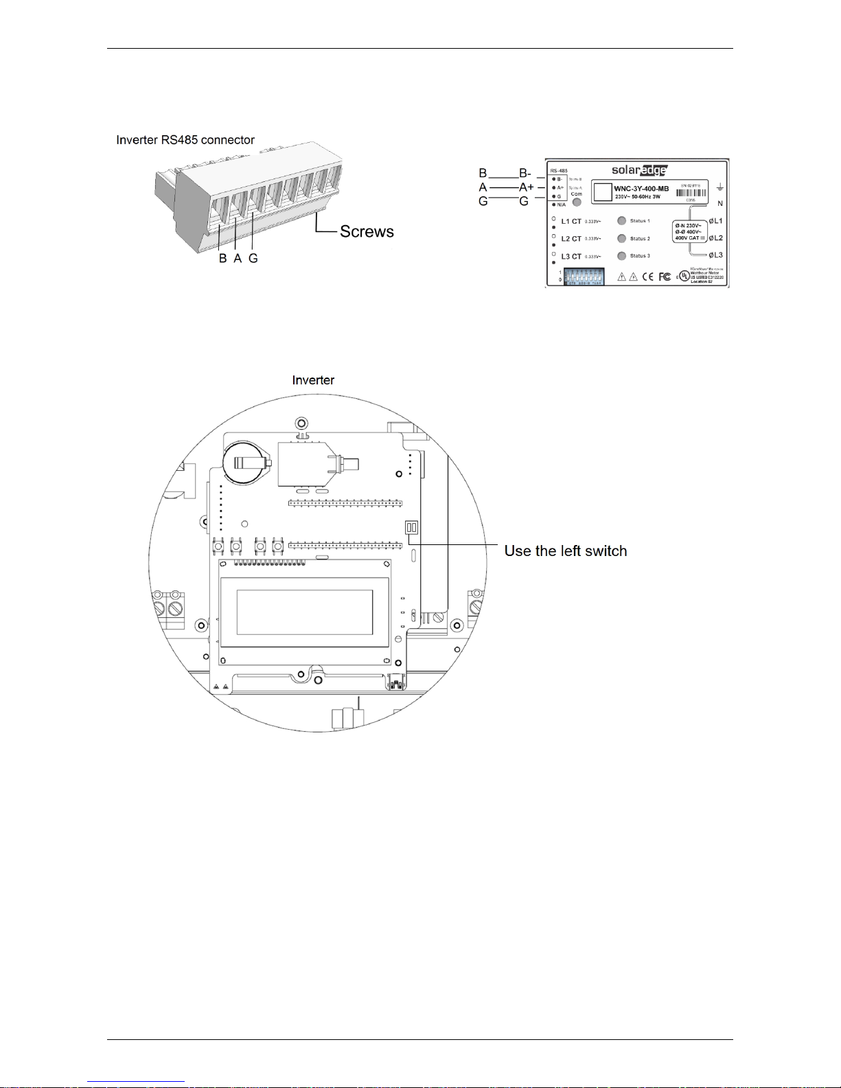
METER (SOLAREDGE ONLY)
41
3. Connect the wires from the meter.
a. If you have a SolarEdge branded meter, connect as illustrated below:
4. If the SolarEdge device is at the end of the RS485 bus, terminate the inverter by switching a
termination DIP-switch inside the inverter to ON (top position). The switch is located on the
communication board is marked SW7 as illustrated below:

42
LABELLING
This information is supplied here as a guide only. Additional labels may be required depending upon the
installation and local requirements. Labels must be constructed to AS 1319 and installed according to
AS 4777.1, AS/NZS 5033 and any local regulations. Refer to aforementioned standards for more information.
The purpose of labelling is to clearly indicate that the electrical installation has multiple supplies and which
circuits are affected by these supplies. Labelling also identifies the components that isolate the various
supplies. Labels relating to the PV system must be placed on the switchboard to which the PV system is
directly connected. If the PV system is directly connected to a distribution board, additional labels must also
be placed on the main switchboard and all intermediate distribution boards. The following table details labels
that are supplied in Solahart PV Systems.
Label
Colour
Location
Black text
on
yellow background
Prominent position on the
switchboard where the
inverter is connected to
White text
on
red background
Adjacent to main switch to
grid supply
White text
on
red background
Adjacent to the isolator for
normal supply to the
distribution board (applicable
only when the inverter is
connected to a distribution
board)
White text
on
red background
Solar inverter main switch if
inverter is located adjacent to
switchboard
OR
Solar plant location to be entered by installer
White text
on
red background
Solar inverter main switch if
inverter is not located
adjacent to main switchboard
Values to be entered by installer
SOLAREDGE SYSTEMS ONLY:
Open circuit voltage:
Inverter maximum DC
operating voltage
Short circuit current:
Inverter maximum
input current
White text
on
red background
Prominent position adjacent
to meter box and building’s
main switchboard

LABELLING
43
Label
Colour
Location
Reflective white text
on
reflective green background
Prominent position on or
adjacent to the meter box
Black text
on
white background
Rooftop and inverter Solar
DC isolators
Black text
on
white background
Inverter AC isolator
Distribution board number to be entered by
installer i.e. DB1
Black text
on
yellow background
Main switchboard (applicable
when the inverter is
connected to a distribution
board)
Black and white
Prominent position adjacent
to the inverter
Black text
on
yellow background
Added below the shutdown
sign (Solahart PV Operating
Procedure)
Black text
on
yellow background
Prominent position adjacent
to the inverter

44
COMMISSIONING
Systems must be commissioned according to AS/NZS 5033. Commissioning tests are required to ensure that
the system complies with the aforementioned standard. Commissioning information is provided here as a guide
only and it is the installer’s responsibility to ensure that the requirements of AS/NZS 5033 are met. A copy of
the relevant commissioning documents must be provided to the owner and a copy kept by the installer.
Before starting any of the tests below, ensure that:
The Main Switch (Inverter Supply) at the AC switchboard is in the OFF position.
The Inverter AC Isolator at the inverter is in the OFF position (if installed).
The Inverter DC Isolator(s) at the inverter are in the OFF position.
The Rooftop DC Isolator(s) are in the OFF position.
Warning: Dangerous DC voltages may be present during the following commissioning procedure.
Appropriate personal protective equipment should be used.
VERIFICATION OF MODULE AND RAIL EARTH RESISTANCE
This test is performed to ensure modules and rails are correctly earthed.
1. Using a multimeter set on the ohms scale, measure between each module and the system earth wire.
Earth resistance must be 0.5 Ω or less.
2. Using a multimeter set on the ohms scale, measure between each rail and the system earth wire. Earth
resistance must be 0.5 Ω or less.
STRING OPEN CIRCUIT VOLTAGE (VOC) TEST
This test is performed to ensure the wiring polarity and continuity of the PV array is correct. Measurements
should be made under stable irradiance conditions close to solar noon if possible. Where multiple strings are
installed, this test procedure must be repeated for each string.
The voltage measurement obtained should be the number of modules in the string multiplied by the Voc of one
module i.e. for a string with 9 X REC280TP modules: String Voc = 9 X 39.2 V DC ≈ 353 V DC. Refer to “Voltage
Tables for SMA and ABB Systems” or “Voltage Tables for SolarEdge Systems” on page 9.
1. Ensure that the Inverter AC Isolator(s) are in the OFF position.
2. Ensure that the Inverter DC Isolator(s) are in the OFF position.
3. Ensure that the Rooftop DC Isolator(s) are in the OFF position.
4. Using a multimeter set on the DC voltage scale, measure between the string positive and negative
terminals at the module side of the string Rooftop DC Isolator and compare the value obtained with the
table below. For SolarEdge systems see note below.
Note (SolarEdge systems only): Each power optimizer in a string will output a voltage of 1 V (±0.1 V).
For example: 9 power optimizers connected in a string should output a voltage of 9 V (±0.9 V).
5. Repeat for each string.
The open-circuit voltage (Voc) of every string must be measured before switching on the inverter and must be
within 5% of the calculated value. If readings are outside the calculated value by more than ±5%, then
connections must be verified for polarity, continuity and possible faults and repaired where necessary. Once
verification has been satisfactorily completed, strings may then be connected to the inverter.

COMMISSIONING
45
SOLAR ISOLATION DEVICE(S) TEST – ROOFTOP DC ISOLATOR(S)
This test is performed to ensure the Rooftop DC Isolator(s) are isolating the string(s) from the inverter when in
the OFF position.
1. Ensure that the Inverter AC Isolator(s) are in the OFF position.
2. Switch all string DC Isolators to the ON position (Rooftop and Inverter DC Isolators).
3. Ensure that the PV system is operating under irradiance conditions greater than 500 W/m
2
.
4. Switch the string Rooftop DC Isolator to the OFF position.
5. Disconnect string positive and negative DC plug connectors from inverter.
6. Using a multimeter set on the DC voltage scale, connect multimeter leads between the disconnected string
plugs. Ensure leads are firmly connected. If a DC voltage is present, the Rooftop DC Isolator or system
wiring is faulty and will require replacing or repairing.
Note (SolarEdge systems only): Each power optimizer in a string will output a voltage of 1 V (±0.1 V).
For example: 9 power optimizers connected in a string should output a voltage of 9 V (±0.9 V).
7. Switch the string Rooftop DC Isolator to the ON position. If a DC voltage is not present, the Rooftop DC
Isolator or system wiring is faulty and will require replacing or repairing.
8. Switch the string Rooftop DC Isolator to the OFF position.
9. Reconnect string positive and negative DC plug connectors to inverter.
10. Repeat for each string.
SOLAR ISOLATION DEVICE(S) TEST – INVERTER DC ISOLATOR(S)
This test is performed to ensure the Inverter DC Isolator(s) are isolating the string(s) from the inverter when in
the OFF position.
1. Ensure that the Inverter AC Isolator(s) is in the OFF position.
2. Switch all string DC Isolators to the ON position (Rooftop and Inverter DC Isolators).
3. Ensure that the PV system is operating under irradiance conditions greater than 500 W/m
2
.
4. Switch the string Inverter DC Isolator to the OFF position.
5. Disconnect string positive and negative DC plug connectors from inverter.
6. Using a multimeter set on the DC voltage scale, connect multimeter leads between the disconnected string
plugs. Ensure leads are firmly connected. If a DC voltage is present, the Inverter DC Isolator or system
wiring is faulty and will require replacing or repairing.
Note (SolarEdge systems only): Each power optimizer in a string will output a voltage of 1 V (±0.1 V).
For example: 9 power optimizers connected in a string should output a voltage of 9 V (±0.9 V).
7. Switch the string Inverter DC Isolator to the ON position. If a DC voltage is not present, the Inverter DC
Isolator or system wiring is faulty and will require replacing or repairing.
8. Switch the string Inverter DC Isolator to the OFF position.
9. Reconnect string positive and negative DC plug connectors to inverter.
10. Repeat for each string.

COMMISSIONING
46
INSULATION RESISTANCE TEST
This test is performed to verify the insulation resistance between the positive DC string wiring and earth and
the negative DC string wiring and earth are both greater than or equal to 1 Megaohm (1 MΩ) as required by
AS/NZS 5033:2014 Clause D4.
An insulation tester capable of applying test voltages of 500V and 1000V is required to perform this test.
Warning: Live voltages of up to 600 VDC will be present during this test. Wear personal protective
equipment to prevent the risk of electric shock and treat DC string wiring as if it were live at all times.
Warning: Do not permit any person to touch any part of the array whist the insulation test is being
performed.
1. Ensure that the Inverter AC Isolator is in the OFF position.
2. Switch the Rooftop DC Isolator(s) to the ON position.
3. Switch the Inverter DC Isolator(s) to the OFF position.
4. Disconnect string positive and negative DC plug connectors from inverter.
5. Connect the insulation tester leads between the disconnected positive string plug and earth. Ensure test
leads are firmly fixed in position.
6. Select the appropriate test voltage on the insulation tester according to the number of modules in the
string (500 V for a string of 6-10 modules; 1000 V for a string of 11-14 modules).
7. Switch the Inverter DC Isolator to the ON position.
Warning: The positive and negative string wiring is now live and will have up to 600 VDC present.
8. Activate insulation tester. The resistance measured must be greater than or equal to 1 MΩ.
9. Switch the Inverter DC Isolator to the OFF position.
10. Connect insulation tester leads between the disconnected negative string plug and earth. Ensure test
leads are firmly fixed in position.
11. Switch the Inverter DC Isolator to the ON position.
Warning: The positive and negative string wiring is now live and will have up to 600 VDC present.
12. Activate insulation tester. The resistance measured must be greater than or equal to 1 MΩ.
13. Switch the Inverter DC Isolator to the OFF position.
14. Reconnect string positive and negative DC connectors to the inverter.
15. For the Two String Configuration, repeat this procedure for the second string.
VERIFICATION OF INVERTER WIRING
This verification is performed to ensure the inverter is correctly and safely wired. Check the Positive and
Negative connectors are fully engaged at the Inverter and any unused inputs have connectors with sealing
plugs installed.
INVERTER COMMISSIONING
Warning: Do not turn on the inverter until all of the previous commission procedure tests/checks have been
satisfactorily completed.
Turn on the PV system (refer to “To Turn PV System On” in the Solahart PV Systems Owner’s Guide) then
commission the inverter according to the commissioning procedure described in the relevant inverter
installation guide for the model inverter installed.
For ABB inverters the start voltage must be correctly set based on the type and size of array to allow the
system to perform correctly. To set the start voltage refer to “ABB Inverter Start Voltage” on page 49.

COMMISSIONING
47
ABB DM-PLUS-B series inverters can be commissioned either using the buttons and inverter LED screen or
through the inverter Built-in Wifi Web User Interface (UI). For details refer to ABB instruction “Quick Installation
Guide UNO-DM-1.2/2.0/3.3/4.0/4.6/5.0-TL-PLUS”.
For SMA inverters that do not have display screens, commissioning is performed by directly connecting a
smart device to the Inverter Built-in WLAN Web User Interface (UI). A laptop, tablet or smartphone is required
for commissioning the inverter. For details refer to “SMA Inverter Commissioning USING Web UI” on page 47.
SMA INVERTER COMMISSIONING USING WEB UI
The following inverter models are commissioned using the Web UI:
SB 1.5/2.5-1 VL-40
SB3.0/4.0/5.0-1AV-40
Prepare the inverter for commissioning
1. Ensure all circuit breakers, inverter and cables are correctly rated, mounted and installed. (PV Array DC
Isolator, DC Load-break switch of inverter to Position I).
2. Switch on the AC Circuit Breaker.
Connecting via WLAN
1. Ensure a Smart device (e.g. computer, tablet pc or
smartphone) and the appropriate web browser (see SMA
Operating Manual) is available.
2. Connect to Wi-Fi network of the inverter named SMA[serial
number].
3. Enter the WLAN Password:
a) Within the first 10 operating hours, the WLAN
password is SMA12345
b) After the first 10 hours of operation, the WLAN
password is the WPA2-PSK sequence, located on the
rating label on the side of the inverter (also found on
the rear side of SMA Quick Reference Guide included
in delivery)
Logging into the User Interface
1. Enter the IP Address in an appropriate web browser:
• For SB3.0/4.0/5.0-1AV-40 enter 192.168.12.3
• For SB1.5/2.5-1VL-40 enter 192.168.100.1
2. In the drop-down list Language, select the desired
language.
3. In the User Group drop-down list, select the entry
Installer.
4. In the New Password field, enter a new desired password,
repeat the password and click Login.

COMMISSIONING
48
Configuring Inverter Settings
1. Once logged in, select ‘Configuration with Installation
assistant’.
2. If internet is available, configure the network connection:
a. Choose appropriate connection type
Ethernet
WLAN
b. Type in network password as required.
c. Select ‘Save and Next’.
3. Select correct Time Zone based on installation location.
Select ‘Save and Next’.
4. Select Country Standard ‘AS4777.2_2015’. Select ‘Save
and Next’.
5. Set Feed in Management parameters if applicable. Default
parameters can be used if no power limitation is required.
Select ‘Save and Next’.
6. The configuration summary page is displayed. Check all
parameter settings to ensure they are entered correctly.
Select ‘Continue’ to finish the configuration process.
Final Commissioning Steps
1. The inverter will undergo a countdown of 60 seconds. Once the inverter connects to the grid, the
green light should stop flashing and glow steadily. This indicates that the system is operating
normally.
2. Register the PV System if the inverter is connected to internet:
a. Go to https://www.sunnyportal.com
b. Select “Plant Setup Assistant” and follow the wizard to complete registration
Provide Sunny Portal login details to the customer.

COMMISSIONING
49
ABB INVERTER START VOLTAGE
The start voltage (VStart) is the DC voltage at which the inverter will begin to transform DC to AC.
Inverter Model UNO-DM-2.0-TL-PLUS-B
UNO-DM-2.0-TL-PLUS-B only has one MPPT with a nominal factory start voltage of 150V. If fewer than 5
modules are connected, the start voltage must be adjusted down in order for the system to function.
The display on this inverter allows the start voltage to be checked and altered as follows:
1. Press and release the ‘ESC’ button.
2. Press and release the down ‘↓’ button until ‘Inverter’ is displayed on the screen. Press and release the
‘Enter’ button.
3. Press and release the down ‘↓’ button until ‘Settings’ is displayed on the screen.
4. Press and release the ‘Enter’ button. ‘Password 0000’ will be displayed on the screen.
5. Enter password ‘0000’ using the arrow keys.
6. Press and release the down ‘↓’ button until ‘VStart’ is displayed on the screen.
7. Press and release the ‘Enter’ button. And the current start voltage setting will be displayed on the screen.
8. Press and release the up ‘↑’ or down ‘↓’ buttons to change the start voltage to 100V.
9. Press and release the ‘Enter’ button to accept the setting.
Inverter Model PVI-3.0 / 4.2 / 5000-TL-OUTD, UNO-DM-3.3/ 4.0/ 5.0-TL-PLUS-B
For all inverter with dual MPPT trackers, each zone input (IN1 and IN2) of this inverter has a nominal factory
preset start voltage of 200V ± 2V.
For single string configurations with fewer than 7 modules, the start voltage for the connected zone input (IN1
or IN2) must be adjusted in order for the system to function correctly and efficiently. The start voltage of the
unused zone input may be left set to the factory preset voltage.
For dual string configurations, and any string with fewer than 7 modules, the start voltage for the connected
zone input (IN1 and/or IN2) must be adjusted in order for the system to function correctly and efficiently.
The display on this inverter allows the start voltage to be checked and altered as follows:
1. Press and release the ‘ESC’ button.
2. Press and release the down ‘↓’ button until ‘Inverter’ is displayed on the screen. Press and release the
‘Enter’ button. (Note: this step is only applicable to UNO-DM-3.3/ 4.0/ 5.0 -TL-PLUS-B models).
3. Press and release the down ‘↓’ button until ‘Settings’ is displayed on the screen.
4. Press and release the ‘Enter’ button. ‘Password 0000’ will be displayed on the screen.
5. Enter password ‘0000’ using the arrow keys.
6. Press and release the down ‘↓’ button until ‘VStart’ is displayed on the screen.
7. Press and release the ‘Enter’ button. ‘VStart1 VStart2’ will be displayed on the screen with an arrow
adjacent to VStart 1.
8. Press and release the ‘Enter’ button to select ‘VStart1’. ‘Set VStart1’ and the current start voltage setting
for the string connected to IN1 will be displayed on the screen.
9. Press and release the up ‘↑’ or down ‘↓’ buttons to change the start voltage to 120V.
10. Press and release the ‘Enter’ button to accept the setting.
11. Press and release the ‘ESC’ button once to return to the menu displaying ‘VStart1 VStart2’.
12. Press and release the down ‘↓’ button. The arrow on the screen will move from ‘VStart1’ to ‘VStart2’.

COMMISSIONING
50
13. Press and release the ‘Enter’ button to select ‘VStart2’. ‘Set VStart2’ and the current start voltage setting
for the string connected to IN2 will be displayed on the screen.
14. Press and release the up ‘↑’ or down ‘↓’ buttons to change the voltage 120V.
15. Press and release the ‘Enter’ button to accept the setting.
16. Press and release the ‘ESC’ button until you exit ‘Settings’ mode.
VERIFICATION OF SYSTEM OPERATION
This step is performed to verify the PV system is operating correctly.
1. Ensure all DC Isolators are in the ON position (Rooftop and Inverter DC Isolators).
2. Ensure the AC Isolator is in the ON position.
3. Ensure the PV system is operating under irradiance conditions greater than 500 W/m
2
.
Note (SolarEdge systems only): Follow system verification procedure outlined in the inverter installation
manual supplied with the inverter. Skip Step 4 below.
4. After waiting for the inverter to connect to the grid, record the ‘Input Voltage’ for each string which will be
alternately displayed on the inverter LCD screen. Check this ‘Input Voltage’ is within ±5% of the value for
the number of modules in each string, according to the following table:
* Values measured at standard test conditions (STC) defined as: irradiance of 1000 W/m2, Spectrum AM 1.5,
and cell temperature 25ºC. Variations from STC values will affect actual Voc and should be allowed for.
Indicative String Vmp @ STC*
Number of modules in string
4 5 6 7 8 9 10
11
12
13
14
REC280TP modules
128
160
191
223
255
287
319
351
383
415
447
REC290TP2 modules
128
161
193
224
257
288
321
353.1
385
417
449

51
ENGINEERING CERTIFICATION

ENGINEERING CERTIFICATION
52

53
SOLAHART PV SYSTEM WARRANTY - AUSTRALIA ONLY
IMPORTANT NOTE: This Limited Warranty covers a range of systems, products and
components. This Warranty only applies in respect of the specific items you have purchased
and which are delivered to you in conjunction with this hard copy Warranty document.
Your new PV System comprises a PV Module, an Inverter, a racking system and balance of system
components (together the PV System). Alternatively, you may add components sourced from Solahart to your
existing PV System and associated products.
The PV System, the Battery, and any other components supplied by Solahart (collectively, the ‘Products’) are
covered by a warranty given by Solahart Industries Pty Ltd ABN 45 064 945 848 of 1 Alan Street, Rydalmere
NSW 2116 (Solahart). The terms of your warranty are set out below. This warranty consists of a number of
parts (not all of which will apply, depending on the Products you have purchased):
A. The specific warranty terms for Modules supplied by Solahart;
B. The specific warranty terms for the LG Chem Battery;
C. The specific warranty terms for Inverters – SMA and ABB;
D. The specific warranty terms for SolarEdge Inverters and associated SolarEdge products;
E. The specific warranty terms for the racking system;
F. The specific warranty terms for the balance of the system;
G. The specific warranty terms for the labour; and
H. General terms which apply to all of the above.
This Limited Warranty is valid in Australia for all Products sold after 17 March 2016. If a subsequent version
of this warranty is published, the terms of that warranty will apply to Products manufactured after the date
specified in the subsequent version.
Solahart issues the following voluntary warranty to:
1. The end-user who purchased the System in Australia and put the System into use for the first time (the
‘Original End-User’); and
2. In the case of SolarEdge Products only, any owner of the Product subsequent to the Original End-User
who provides proof of title transfer, provided that the Product has never been relocated from its original
installation location without the express written consent of Solahart.
This warranty is in addition to any rights and remedies that you may have under the Australian Consumer Law.
Solahart offers national service through its Dealer network. Solahart will repair or replace parts subject to the
terms of this Limited Warranty. Solahart, in addition can provide preventative maintenance and advice on the
operation of the PV System. You can contact Solahart on 1800 638 011 to arrange a service call or to find out
details about this warranty.
Notification of a claim under this Limited Warranty must be given without undue delay after detection of the
defect and prior to the expiration of the applicable Warranty Period and in accordance with the procedure set
out below.
PART A - MODULES
Warranty coverage for the Module
Subject to the terms and conditions of this Limited Warranty, Solahart warrants that the Modules:
1. Are free from defects in material and workmanship for a period of (10) years after the date of installation
of the Module (the ‘Module Warranty Period’) if installed and used in accordance with the installation
instructions set out in the Solahart Owner’s Guide and Installation Instructions – PV Systems which
accompanies the Module, and with all relevant statutory and local requirements in the State or Territory
in which the Module is installed.

SOLAHART PV SYSTEM WARRANTY - AUSTRALIA ONLY
54
2. Will remain safe and operational if cable and connector plugs are installed professionally and are not
permanently positioned in water; provided however, that damage to the cable caused by abrasion on a
rough surface due to insufficient fixing or to unprotected running of the cable over sharp edges is excluded.
Damage caused by animals is also excluded.
3. Will not experience freezing up of the aluminium frames if installed correctly.
The outer appearance of the Module, including scratches, stains, rust, mould, discoloration and other signs of
normal wear and tear, which occurred after delivery or installation, do not constitute defects, provided the
functionality of the Module is not affected. Glass breakage constitutes a defect only if not caused by any
external influence.
If a defect (as described above) occurs during the Module Warranty Period materially affecting the functionality
of the Module, Solahart will, at its sole option:
1. Repair the defective Module;
2. Replace the Module with an equivalent product; or
3. Refund the original purchase price for the Module as determined by Solahart.
Warranty Terms, Limitations and Exclusions
This Limited Warranty applies to the original Module and to any approved replacement parts and is not
transferable by the Original End-User, except to the subsequent owner of the property at which the original PV
System was installed and remains installed, provided that this PV System has not been altered in any way or
moved from the structure or property at which it was originally installed.
There are many factors that affect the output of your Module. Solahart does not warrant a specific power output
for your Modules. All modules degrade over time and power output is subject to many variables including the
age of the Module.
PART B – BATTERIES
Warranty coverage for capacity retention – LG Chem Battery
Subject to the terms and conditions of this Limited Warranty, Solahart warrants that the LG Chem Battery will
retain the capacity levels specified in Exhibit A during the applicable periods identified in the Exhibit (each, an
‘LG Chem Capacity Retention Warranty Period’).
Remedies
If Solahart determines that a reported defect in relation to a LG Chem Battery is eligible for coverage under
this Limited Warranty, Solahart will, at its sole option:
1. Repair the defective LG Chem Battery;
2. Replace the LG Chem Battery; or
3. Provide a Refund to be calculated in accordance with the formula below.
100% of the purchase price from the initial installation date to 24th month
72% of the purchase price from 25th to 36th month
58% of the purchase price from 37th to 48th month
44% of the purchase price from 49th to 60th month
30% of the purchase price from 61st to 72nd month
16% of the purchase price from 73rd to 84th month
6% of the purchase price from 85th to 96th month
4% of the purchase price from 97th to 108th month
2% of the purchase price from 109th to 120th month

SOLAHART PV SYSTEM WARRANTY - AUSTRALIA ONLY
55
PART C – INVERTERS – SMA AND ABB
Warranty coverage for SMA and ABB Inverters
Solahart warrants that the Inverter, when located at its original installation, will operate in accordance with its
specifications in the Solahart's Owner’s Guide and Installation Instructions for a period of five (5) years from
the date of installation of the inverter. If the Inverter fails to operate in accordance with its specifications and
this materially affects the usability of the Inverter, Solahart will, at its sole option:
1. Repair the Inverter;
2. Provide a replacement Inverter swapped; or
3. Refund the original purchase price for the Inverter as determined by Solahart.
PART D – INVERTERS AND ASSOCIATED COMPONENTS – SOLAREDGE
(In this Part D, a reference to “Products” is to the SolarEdge Products as described below).
Warranty coverage for SolarEdge Inverter
Subject to the terms and conditions of this Limited Warranty, Solahart provides a warranty against defects in
workmanship and materials in relation to the SolarEdge Inverter, when located at its original installation, for a
period of ten (10) years commencing on the earlier of:
1. 4 months from the date the Inverter is shipped from the manufacturer; and
2. The date of installation of the Inverter.
Warranty coverage for StorEdge Interface
Subject to the terms and conditions of this Limited Warranty, Solahart provides a warranty against defects in
workmanship and materials in relation to the StorEdge Interface for a period of ten (10) years commencing on
the earlier of:
1. 4 months from the date the Interface is shipped from the manufacturer; and
2. The date of installation of the Interface.
Warranty coverage for Power Optimizers
Subject to the terms and conditions of this Limited Warranty, Solahart provides a warranty against defects in
workmanship and materials in relation to the Power Optimizers for a period of ten (10) years commencing on
the earlier of:
1. 4 months from the date the Power Optimizers are shipped from the manufacturer; and
2. The date of installation of the Power Optimizers.
For all Power Optimizers with a part number ending in C, this warranty does not apply to the input connector.
Warranty coverage for Power Meter
Subject to the terms and conditions of this Limited Warranty, Solahart provides a warranty against defects in
workmanship and materials in relation to the Power Meter for a period of five (5) years commencing on the
earlier of:
1. 4 months from the date the Power Meter is shipped from the manufacturer; and
2. The date of installation of the Power Meter.
Remedies
If Solahart determines that a reported defect in relation to a Product is eligible for coverage under this Limited
Warranty (including retention capacity), Solahart will, at its sole option:
1. Repair the defective Product;
2. Issue a credit note for the defective Product in an amount up to its actual value at the time buyer notifies
Solahart of the defect, as determined by Solahart, for use toward the purchase of a new Product; or
3. Provide the buyer with replacement units for the Product.

SOLAHART PV SYSTEM WARRANTY - AUSTRALIA ONLY
56
Exclusions
The Limited Warranty does not apply to components which are separate from the Products, ancillary
equipment and consumables, such as, for example, cables, fuses, wires and connectors.
Beneficiary of Limited Warranty
The Limited Warranty only applies to the buyer who purchased the Products from Solahart, for use in
accordance with their intended purpose (‘Original Buyer’). The Limited Warranty may be transferred from the
Original Buyer to any assignee, and will remain in effect for the time period remaining under the above
Warranty Periods, provided that the Products are not moved outside their original country of installation and
any reinstallation is done in accordance with the installation directions and use guidelines accompanying the
Products.
PART E – THE RACKING SYSTEM
Warranty coverage for the Racking System
Solahart warrants that the racking system supplied with the PV System shall be free from defects in material
and workmanship for a period of five (5) years from the date of installation.
This Warranty shall be void if installation of the racking system is not performed in accordance with the Owner’s
Guide and Installation Instructions, or if the racking system has been modified, repaired, or reworked in a
manner not previously authorized by Solahart in writing. If within the specified Warranty period the racking
system shall be reasonably proven to be defective, then Solahart shall repair or replace the defective
component(s) at Solahart’s sole discretion. Such repair or replacement shall completely satisfy and discharge
all of Solahart’s liability with respect to this Limited Warranty.
PART F - BALANCE OF THE SYSTEM
Warranty coverage for the balance of the system
The balance of the PV System (BOS) consists of PV module cabling, circuit breakers, isolators, enclosures
and labels. Solahart warrants that the BOS supplied by it will operate in accordance with its specifications in
the Owner’s Guide and Installation Instructions for a period of five (5) years from the date of installation of the
BOS. If the BOS fails to operate in accordance with its specifications and this materially affects the usability of
the BOS, Solahart will, at its sole option, repair or replace the defective component.
PART G - LABOUR WARRANTY
Warranty coverage for labour – PV System and LG Chem Battery
In addition to the above coverage, Solahart provides you with five (5) years of coverage, from the date of
installation, for all labour costs involved with inspection by Solahart, removal or installation of warranted parts
or components by Solahart of your PV System. Other than this five (5) years coverage, this Warranty does not
cover, nor will Solahart reimburse, any on-site labor or other costs incurred in connection with the inspection,
de-installation or removal of defective parts or components, or the re-installation of replaced or repaired parts
or components for your PV System.
Warranty coverage for labour - SolarEdge Products
If Solahart determines that a reported defect in relation to a SolarEdge Product is eligible for coverage under
this Limited Warranty and Solahart decides to repair the Product or part(s), warranty coverage includes labour
and material costs necessarily incurred to correct the Product defect; and where Solahart decides to replace
the Product or part(s) to which the Limited Warranty applies, warranty coverage includes the cost of the
replacement of the Product or part(s). All other costs will be borne by you.
PART H - GENERAL TERMS
Back-up if sole or dominant power supply
If the PV System is to be the sole or dominant power supply for your business or application, you should ensure
that you have back up redundancy if the PV System were to become inoperable for any reason. We suggest
that you seek advice from your electrician or qualified professional about your needs and build backup
redundancy into your electricity supply system.
Application of this warranty
This warranty requires the Products to be installed according to the latest safety, installation and operation
instructions provided by Solahart and with all relevant statutory and local requirements in the State or Territory
in which the Products are installed, and does not apply to defects, damage, malfunction, power output or
service failures which have been caused by:
1. Storage, installation, commissioning, repair, modifications, alterations, attachments or movement to or of
the Product, or (in the case of the LG Chem Battery) opening of the external casing of the LG Chem

SOLAHART PV SYSTEM WARRANTY - AUSTRALIA ONLY
57
Battery, performed by someone other than a Solahart Dealer or a Solahart Accredited Service Agent or
otherwise without the prior written consent of Solahart;
2. Abuse, misuse or abnormal use, accident, negligent acts, power failures or surges, force majeure events
including but not limited to lightning, fire, flood, hail, extreme cold weather, or any other natural disaster,
any other force majeure event, pest damage, accidental breakage, actions of third parties, and any other
events or accidents outside Solahart’s control and/or not arising under normal operating conditions;
3. Operating the Product in an unintended environment or under incorrect safety or protection conditions;
4. Failure to install, operate and/or maintain the Product in accordance with the applicable Solahart Owner’s
Guide and Installation Instructions;
5. Transport damage;
6. Wear and tear from adverse conditions including corrosive atmospheric conditions e.g. salt, ocean spray,
dust storm or other weather damage;
7. Cosmetic defects;
8. Any improper attachment, installation or application of the Product, and in respect of the PV System, any
insufficient framing if the PV System is a frameless module;
9. Any attempt to extend or reduce the life of the Product, whether by physical means, programming or
otherwise, without the prior written consent of Solahart;
10. Removal and reinstallation at a location other than the original installation location, without the prior written
consent of Solahart;
11. Insufficient ventilation of the Product;
12. Failure to observe the applicable safety regulations; or any factor identified in the applicable Solahart
Owner’s Guide and Installation Instructions; or
13. Ignoring safety warnings and instructions contained in all documents relevant to the applicable Product.
If your claim relates to a failure to operate in accordance with the Solahart Owner’s Guide and Installation
Instructions as a result of one of the factors listed above, Solahart may charge you at its standard rates for its
time and materials related to your claim.
Without limiting the above exclusions:
1. In relation to LG Chem Batteries, the Warranty does not cover damage from any of the following activities:
(a) improper transportation, storage, installation or wiring; (b) modification, alteration, disassembly, repair or
replacement without authorization from Solahart; (c) noncompliance with the manufacturer’s product
Installation Manual; (d) external influences including unusual physical or electrical stress (power failure
surges, inrush current, lightning, flood, fire, accidental breakage, etc); or (e) use of an incompatible inverter,
rectifier or power conditioning system.
2. In relation to SolarEdge Products, the Warranty does not cover: (a) Products which are installed or
operated not in strict accordance with the accompanying instruction documentation, including without
limitation, not ensuring sufficient ventilation for the Product as described in the applicable installation
guide; (b) Products which are opened, modified or disassembled in any way without Solahart’s prior written
consent; (c) Products which are used in combination with equipment, items or materials not permitted in
the instruction documentation or in violation of local codes and standards; or (d) cosmetic or superficial
defects, dents, marks or scratches which do not influence the proper functioning of the Products.
Location and positioning
Where the Product is installed outside the boundaries of a metropolitan area (as defined by Solahart) or further
than 25 km from a regional Solahart Dealer, the cost of transport, insurance and travelling costs to the nearest
Solahart Dealer shall be the owner’s responsibility. Where the Product is installed in a position that does not
allow safe, ready access, the cost of accessing the site safely, including the cost of additional materials
handling and/or safety equipment, shall be the owner’s responsibility.
Replacements
Solahart may use new, used, remanufactured or refurbished parts or products when repairing or replacing any
Product under this Limited Warranty. Any exchanged or replaced parts or Products will become the property

SOLAHART PV SYSTEM WARRANTY - AUSTRALIA ONLY
58
of Solahart. Goods presented for repair may be replaced by refurbished goods of the same type rather than
being repaired.
If the Product is repaired or replaced under this Warranty, the remainder of the applicable Warranty Period will
apply to the repaired or replaced Product and the repaired or replaced Product or parts will not carry a new
Solahart Warranty. The Warranty Periods set out above will not be extended in any way in the event of a
replacement or repair of a Product, but this does not affect any rights you may have under the Australian
Consumer Law in relation to the replaced or repaired Product (see the section below entitled “The Australian
Consumer Law” for further details).
Limitation of this warranty
This Limited Warranty is provided voluntarily and free of charge and does not constitute an independent
guarantee promise. Therefore, if any defect materially affects the functionality of any Product, the remedies
under this Warranty are limited exclusively to the remedies set out above in the warranty cases specified
herein.
Subject to any statutory provisions to the contrary, Solahart assumes no warranties, express or implied, written
or oral, other than the warranties made herein and specifically disclaims all other warranties, merchantability
or fitness for a particular purpose and Solahart excludes all liabilities for any special, incidental, indirect,
consequential or punitive damages arising from or in connection with the use or loss of use of the Product to
perform as warranted, regardless of the form of action and regardless of whether a party has been informed
of or otherwise might have anticipated the possibility of such damages; including but not limited to damages
for loss of power, lost profits or savings nor expenses arising from third-party claims. This does not apply to
the extent Solahart is liable under applicable mandatory laws.
If you require a call out and we find that the fault is not covered by Solahart's warranty, you are responsible for
our standard call out charge. If you wish to have the relevant component repaired or replaced by Solahart that
service will be at your cost.
Entitlement to claim under this warranty
To be entitled to make a claim under this warranty you need to:
1. Provide proof of purchase documentation and be the owner of the Product or have the consent of the
owner to act on their behalf.
2. Contact your Solahart dealer without undue delay after detection of the defect and, in any event, within
the applicable Warranty Period.
You are not entitled to make a claim under this warranty if the relevant Product:
3. Does not have its original serial numbers and type plate or numbers are illegible; or
4. Is not installed in Australia.
Warranty claim procedure
If you wish to make a claim under this warranty, you need to:
1. Contact your Solahart dealer, provide proof of purchase (and in the case of a SolarEdge Product, any
subsequent transfers of ownership of the Product) and owner’s details, address of the Product, a contact
number and date of installation of the Product, the serial number of the Product, and a description of the
alleged defect(s).
2. Solahart will arrange for the Product to be tested and assessed. Solahart will inform you whether this will
occur on-site or whether the Product must be sent elsewhere for testing and assessment.
3. If Solahart determines in its sole discretion that you have a valid warranty claim, Solahart will organise for
the repair or replacement of the Product or any component in accordance with this warranty.
Any expenses incurred in the making of a claim under this Warranty will be borne by you.
The Australian Consumer Law
Our goods come with guarantees that cannot be excluded under the Australian Consumer Law. You are
entitled to a replacement or refund for a major failure and compensation for any other reasonably foreseeable
loss or damage. You are also entitled to have the goods repaired or replaced if the goods fail to be of
acceptable quality and the failure does not amount to a major failure.

SOLAHART PV SYSTEM WARRANTY - AUSTRALIA ONLY
59
Exhibit A
LG CHEM CAPACITY RETENTION LEVELS
References in this Exhibit to the “Product” are to a LG Chem Battery.
The Product will retain at least 60% of Nominal Energy* when the Product is operated under normal use,
consistent with the specification and the Installation Manual provided by LG Chem is followed until the
earliest to occur of:
(a) 10 years after the date of the initial installation; or
(b) the Product has had a minimum Energy Throughput as per the table below:
Product Name
Nominal Energy
Energy Throughput
RESU10H
9.8kWh
27.4MWh
* Nominal Energy means the initially rated capacity of the Products as printed on the label of the Products.
During measurement of the Product’s capacity:
The ambient temperature will be 25~30℃
The initial battery temperature from BMS: 25~30℃
Charging/discharging method:
-
Charge: 0.2CC/CV (Constant voltage: RESU7H_BPI126V/
RESU10H_BPI 176.4V, Cut-off current 0.05C)
-
Discharge: 0.2CC (Cut-off voltage: RESU7H_BPI 90V/
RESU10H_BPI 126V)
-
Current at 0.2C: 12.6A
Current and voltage measurement at battery DC side

Revision Date: 2017 September 122233G
60
Solahart Industries Pty Ltd (A.B.N. 45064945848)
Registered Office
1 Alan Street (PO Box 7508, Silverwater, 2128)
Rydalmere New South Wales 2116
Australia
For SERVICE Telephone - 1800 638 011
or your nearest Solahart Dealer
For Sales Telephone - 1300 769 475
or your nearest Solahart Dealer
www.solahart.com.au
 Loading...