


AUTOMATIC/MANUAL TRANSMISSION REMOTE STARTER
EXTENDED INSTALL GUIDE
iSeries
Revision 4.02 - 08/2015 FW 51+

12V CONSTANT IN RED 1
( + ) 500mA 12V TO STARTER
( + ) 500mA 12V TO IGNITION
SYSTEM GROUND BLACK 4
( + ) 500mA 12V TO ACCESSORY
*
(+) 500mA *12V TO 2nd IGN/AUX/STRT/SIREN
( - ) 325mA LOCK GREEN 1
( + ) 12V+ OUTPUT EMPTY 2
( - ) 325mA UNLOCK BLUE 3
NOT USED BLACK/BROWN 1
NOT USED BLACK/GREEN 2
NOT USED BLACK/BLUE 3
NOT USED BLACK/YELLOW 4
* ( - ) 325mA DISARM BLUE/WHITE 1
* ( - ) 325mA RE-ARM GREEN/WHITE 2
( - ) 325mA TRUNK RED/WHITE 3
( + ) BRAKE IN PINK 4
( - ) PARK BRAKE BLACK/WHITE 5
( - ) DOOR IN GREEN 6
( + ) DOOR IN PURPLE 7
(-) HORN BROWN/BLACK 8
( - ) HOOD SWITCH IN GRAY 9
( - ) MULTIPLEX INPUT **GRAY/BLACK 10
(AC) TACHOMETER IN PURPLE/WHITE 11
* ( - ) 325mA GWA/ AUX WHITE/PURPLE 12
* ( - ) 325mA IGNITION/ AUX PINK/BLACK 13
* ( - ) 325mA ACCESSORY/ AUX ORANGE/BLACK 14
* ( - ) 325mA STARTER/ AUX PURPLE/BLACK 15
* ( - ) 325mA PARK LIGHT/ AUX WHITE/BLACK 16
PURPLE 2
PINK 3
ORANGE 5
PINK/WHITE 6
* These Connections are PROGRAMMABLE
12V TO STARTER PURPLE 1
12V CONSTANT IN RED 2
*12V TO 2nd IGN/ACC/STRT/PROG
12V TO ACCESSORY ORANGE 4
12V CONSTANT IN RED / WHITE 5
12V TO IGNITION PINK 6
PINK/WHITE 3
GROUND AUX ALARM TRIGGER / GLOW PLUG
GROUND THROUGH 12K (-) TRIGGER START
GROUND THROUGH 27K ARM & LOCK
GROUND THROUGH 47K DISARM & UNLOCK
WIR E LOOP
UNCUT = MANUAL
CUT = AUTOMATIC
( - ) GROUND WHEN ARM 4
12V+ OUTPUT 3
WARN AWAY 2
INSTANT TRIGGER 1
( - ) 325mA GWR WHITE/PURPLE 1
( - ) 325mA GROUND BLACK 2
( + ) 12V+ OUTPUT RED 3

Installation Guide Wiring Reference (SEE HOW TO TEST VEHICLE WIRES AT THE END OF THIS MANUAL)
CN1 (MAIN)
These Wires are limited to 1 amp. Do not connect to High Current vehicle wires. If you are installing to a
vehicle where high current is needed please use Plug in Relay Pack.
RED - (+) 12V INPUT - This wire is the 12V(+) input for the remote starter. Connect this wire to a 12V(+) Constant wire on
the vehicle.
BLACK - This wire is the system ground input. Connect this wire to bare metal on the vehicle chassis. Solace recommends a
kick panel and scraping away any paint. All your ground connections from the remote starter and any add-ons such as alarm
sensors, or bypass module should be grounded at the same point.
PURPLE - (+) START OUTPUT - This wire will send out a 12V(+) pulse during crank. Connect this wire to the (+) Starter
wire on the vehicle.
ORANGE - (+) ACCESSORY OUTPUT - This wire sends out 12V(+) signal but shuts off during the crank cycle. Connect
this wire to the (+) Accessory wire on the vehicle.
PINK - (+) IGNITION INPUT/OUTPUT - This wire sends out 12V(+) signal during remote start and during the crank cycle.
This wire is also the ignition feed for the remote starter and is required for programming. Connect this wire to the (+) Ignition
wire on the vehicle.
PINK/WHITE - (+) SELECTABLE OUTPUT - This wire is programmable in Menu 2-01. Whatever it is programmed for it
will duplicate the output for a 2nd wire. It is default set to (+) Ignition. Connect this wire to either 2nd Ignition, 2nd Starter, or
2nd Accessory. Please be sure to program for the according wire on vehicle. This wire can also be programmed to control a
(+) Positive trunk release, (+) PUSH TO START BRAKE output, or SIREN. Connect to a positive trunk release circuit if needed
and program Menu 2-19 to the desired setting.
CN2 (LOCKS)
GREEN- (-) 325mA LOCK OUTPUT - This wire will send a (-) pulse whenever lock is pressed. Connect this wire to the
vehicle’s NEGATIVE lock wire. DO NOT connect to any wire other than negative. This is a programmable output that can be
programmed for timing, number of pulses, and when it turns on. Please see Menu 1-02, 1-03, 1-05, 1-12, and 1-13
EMPTY- (+) 1 AMP POSITIVE OUTPUT - This empty spot will send a constant 12V(+) output that can be used to trip a
relay or a Power Door Lock Module. DO NOT use this wire to drive reverse polarity door locks. DO NOT connect to a high
amperage circuit as damage may occur.
BLUE- (-) 325mA UNLOCK OUTPUT - This wire will send a (-) pulse whenever unlock is pressed. Connect this wire to the
vehicle’s NEGATIVE unlock wire. DO NOT connect to any wire other than negative. This is a programmable output that can
be programmed for timing, number of pulses, and when it turns on. Please see Menu 1-02, 1-04, and 1-05.

CN3 (AUXILIARY)
NOT USED FOR REMOTE START
CN4 (INPUT / OUTPUT)
BLUE/WHITE - (-) 325mA DISARM - This wire sends a pulse to disarm the factory content alarm system before the
remote start sequence begins, with every unlock command, and trunk release. This wire can be programmed in Menu 1-06,
1-08, and 1-10 for different functions, it can also be programmed in Menu 4-02 for different outputs. Connect this wire to
either the factory disarm wire or door pin wire to control the factory alarm systems on most vehicles. This wire can also be
connected to the factory door pin wire to wake up a BCM on some vehicles that require this.
GREEN/WHITE - (-) 325mA REARM - This wire sends a pulse to rearm the factory content alarm system after the remote
start sequence ends, and with every lock command. This wire can be programmed in Menu 1-08 for different functions, it can
also be programmed in Menu 4-03 for different outputs. Connect this wire to the factory rearm wire to control the factory
alarm on most vehicles. This wire can also be used to pulse door pins to shut off auto lights, or rearm security on some
vehicles.
RED/WHITE - (-) 325mA TRUNK RELEASE - This wire will send out a negative pulse when the trunk command is
received. As default the doors will unlock before the trunk pulse is sent. This wire can be programmed in Menu 1-08, and
1-09 for different timing and features. It can also be changed to a latched output in Menu 4-01. Connect this wire to a
negative trunk wire on the vehicle. If the vehicle has a positive trunk release circuit please either use a relay or the PINK/
WHITE wire on CN1 and program Menu 2-01 to (+)Trunk.
PINK - (+) FOOT BRAKE STATUS INPUT - This wire is the brake shutdown wire and MUST be connected to the vehicle’s
(+) brake light wire when the foot brake is depressed. This wire will disengage the remote starter when 12V is applied, it
also is used for the tach learning process. NOTE - Some newer vehicles must have the ignition on for the brake lights to be
activated.
BLACK/WHITE - (-) PARK BRAKE STATUS INPUT - This wire is the emergency brake input wire and is required for
MANUAL TRANSMISSION installations. Connect this wire to the (-) emergency brake wire on the vehicle that goes to ground
when the emergency brake is engaged. This wire is used to set the remote starter into “reservation mode” and/or “turbo
timer” mode.
GREEN - (-) DOOR STATUS INPUT - This wire is the negative door status trigger input to the remote start and
detects when the door(s) are open. This wire MUST be connected to all doors on the vehicle when installed into a manual
transmission vehicle (or the (+) door status wire). Connect this wire to the vehicle’s wire that goes to ground when the door
is open.
PURPLE - (+) DOOR STATUS INPUT - This wire is the positive door status trigger input to the remote start and
detects when the door(s) are open. This wire MUST be connected to all doors on the vehicle when installed into a manual
transmission vehicle (or the (-) door status wire). Connect this wire to the vehicle’s wire that goes to positive (12V+) when the
door is open.
GRAY - (-) HOOD STATUS INPUT - This wire is the hood status trigger input to the remote start and detects when the
hood is open. This wire MUST be connected so that the remote start cannot engage when the hood is open or the vehicle is
being serviced. Connect this wire to the supplied hood pin switch and test to ensure that there is ground when the hood is
open and neutral when the hood is closed.

GRAY/BLACK - (+/-) WAIT TO START/MULTIPLEX INPUT - This wire is used to detect the Glo Plug light on diesel
engines. With this wire connected, the crank will be delayed until the glow plug light goes out. This wire will monitor either
a (+) or (-) glow plug light and wait up to 30 seconds before cranking. If you wish to set a specific timed delay do not connect
this wire and program the desired time in Menu 2-04. When used a multiplex input his wire is a multipurpose resistance input
wire that has the capabilities to allow multiple inputs from trunk status to disarm in. Please follow the multiplex chart for
more info, must be programmed in Menu 2-05
PURPLE/WHITE - (AC) TACHOMETER/RPM INPUT - This wire is the tachometer or RPM signal input. Connect this
wire to a valid tach source, i.e. coil pack or injector. This wire is monitored by the remote starter and disengages the crank
output once the vehicle is running. Once this wire is connected you must perform a “tach learn” by starting the vehicle by key
and holding the brake while pressing the program button once. If you wish to use a tachless setting or tach through data link
DO NOT connect this wire and perform a “tach learn” and the module will automatically detect which tach setting is best for
the vehicle. You can also program this setting in Menu 2-13.
WHITE/PURPLE - (-) 325mA GROUND WHEN ARMED OUTPUT - This is a programmable output wire. It is set to
default as a Ground When Armed, meaning when the remote starter is in a locked state this wire will have a ground output.
When the remote starter is in the unlocked state this wire will be in a neutral state. This wire can be programmed to perform
multiple other features. Please see Menu 4-04 for a selection of outputs that can be programmed to.
PINK/BLACK - (-) 325mA IGNITION OUTPUT - This is a programmable output wire. It is set to default as a (-)Ignition
output that will duplicate what the Pink (+) Ignition wire on CN1 does. NOTE this is a 325mA (-) output and can be used with
a relay to convert to a (+) Positive output (see relay guide). This wire can be programmed to perform multiple other features.
Please see Menu 4-05 for a selection of outputs that can be programmed to.
ORANGE/BLACK - (-) 325mA ACCESSORY OUTPUT - This is a programmable output wire. It is set to default as a
(-) Accessory output that will duplicate what the Orange (+) Accessory wire on CN1 does. NOTE this is a 325mA (-) output
and can be used with a relay to convert to a (+) Positive output (see relay guide). This wire can be programmed to perform
multiple other features. Please see Menu 4-06 for a selection of outputs that can be programmed to.
PURPLE/BLACK - (-) 325mA STARTER OUTPUT - This is a programmable output wire. It is set to default as a (-)
Starter output that will duplicate what the Purple (+) Starter wire on CN1 does. NOTE this is a 325mA (-) output and can be
used with a relay to convert to a (+) Positive output (see relay guide). This wire can be programmed to perform multiple other
features. Please see Menu 4-07 for a selection of outputs that can be programmed to.
WHITE/BLACK - (-) 325mA PARK LIGHT OUTPUT - This is a programmable output wire. NOTE this is a 325mA (-)
output and can be used with a relay to convert to a (+) Positive output (see relay guide). This wire can be programmed to
perform multiple other features. Please see Menu 4-08 for a selection of outputs that can be programmed to.
BROWN/BLACK - (-) 325mA HORN OUTPUT - This wire is sends out a 325mA output to control the vehicles horn.
Connect this wire to the (-) Horn wire on the vehicle. This wire can also be used as (-) Siren wire. This wire is programmable
for multiple features and it’s timing can be changed in Menu 3-06, 3-07, and 3-08.
CN5 (ANTENNA)
This connector is used for the antenna, Solace PC Cable (SPCC) for firmware updates, and also the Solace
Handheld Programmer (SHHP) which can be used to program all features of this remote starter.

CN6 (RS232 BYPASS)
This connector is used to plug in Fortin, iDatalink, and/or Expresskit bypass modules. Solace remote starters
are 2-Way datalink compatible with all manufacturers. Please see either manufacturer installation guides for
more info. The required data protocol must be selected in Menu 2-11. It is set to 2-Way iDatalink protocol at
default. An optional cable is required when using Expresskit Bypass modules.
CN7 (SHOCK SENSOR)
PIN 1 - (-) INSTANT TRIGGER INPUT - If this wire receives a ground signal from any sensor the alarm will go into full
trigger mode. Connect this wire to the instant trigger wire of an external alarm sensor.
PIN 2 - (-) WARN AWAY TRIGGER INPUT - If this wire receives a ground signal from any sensor the alarm give’s a warn
away consisting of 3 siren chirps/horn honks, notifying the individual the car is equipped with an alarm system. This also
monitors the exterior zone of a proximity sensor. Connect this wire to the pre-warn or pre-shock to an eternal alarm sensor.
PIN 3 - 12V (+) POSITIVE OUTPUT - This wire supplies a 12V (+) output is can be used for auxiliary alarm sensors such
as shock, tilt, audio, and proximity.
PIN 4 - (-) GROUND OUTPUT - This wire supplies a ground (-) output is can be used for auxiliary alarm sensors such as
shock, tilt, audio, and proximity.
CN8 (BYPASS SUPPLY)
WHITE/PURPLE - (-) 325mA GROUND WHEN RUNNING - This wire will send a (-) output whenever the remote start
is engaged This wire can be used in multiple scenarios, the most common is connecting to a bypass module so that it turns
on when remote starting.
RED - (+) 1 AMP POSITIVE OUTPUT - This wire supplies a 12V (+) output that can be used for a bypass module input,
the coil side of a relay, or optional low amperage accessories such as GPS modules, or alarm sensors. DO NOT connect to a
high amperage circuit as damage may occur.
BLACK- (-) 325mA GROUND OUTPUT - This wire supplies a (-) ground output that can be used for a bypass module
ground input, the coil side of a relay, or optional low amperage accessories such as GPS modules, or alarm sensors.
OPTIONAL RELAY PACK
The optional relay pack is used when High Current Output is required on older vehicles. The Relay Pack snaps
in and can only be removed by removing 2 screws on bottom of relay pack and separating the case.
See Relay Pack Installation sheet included for wire descriptions.

PROGRAMMING
TRANSMITTER LEARNING
Important! The remote starter will hold 3 transmitter codes. It is recommended that when programming in transmitters, you fill up all three
transmitter codes, even if only using one or two transmitters. This will clear all other transmitter coding from the unit and prevent stray coding
or possible interference from other remote transmitters.
1. Turn Ignition ON-OFF-ON.
2. Press the valet switch TWICE (button) in the antenna, siren/horn (optional) will chirp once each time button is pressed.
3. Press and hold the valet switch, siren/horn will chirp 3 times & parking lights will turn on to indicate you have entered Transmitter
Learning Mode.
4. Press Button 1 (Lock) of every transmitter to be coded. For 2-Button Remotes press both buttons together, for 1 Button remotes press
the Start button. The siren/horn will chirp once and the parking lights will flash once to indicate successfully learning. System will exit
Learn Mode and lights will turn off after 15 seconds of no activity.
5. Turn ignition OFF and the unit will exit code-learning mode.
TACH LEARNING
1. Start the vehicle with the key.
2. Press foot brake and hold down.
3. Within 10 seconds, press and release the valet switch. The unit will enter Tach Learning Mode automatically.
4. If a Tach signal is detected, the parking light will flash and siren/horn will chirp according to Chart below.
2 FLASHES - Tach Learn - Hard wired Tach Source from vehicle or hard wired output from bypass module
3 FLASHES - Data Tach Learn - Tach signal from bypass module through 2-Way Datalink
4 FLASHES - Tachless Mode - No tach wire is connected and remote starter monitors the vehicle system to ensure it is running
10 FLASHES - Tachless Mode Not allowed in Manual Transmission
ENTERING PROGRAM MODE
1. Turn ignition ON-OFF-ON. (Leaving Key is ON position)
2. Press the valet switch 1 time and release.
The parking lights will flash and the siren/horn will chirp once to confirm.
3. Press and Hold valet button for 3 seconds. The system confirms with 1 siren/horn pulse and park light flash to confirm that it is now in
Program Mode.
Selecting Program Menu
1. Once Program mode has been entered, pressing the remote will select the different program menus as below.
Button 1 ( Lock) will select MENU 1 – 1 light flash siren / horn chirp
Button 2 (Unlock) will select MENU 2 - 2 light flashes siren / horn chirps
Once a MENU is selected by remote, the system will be in at Setting 0, which is the reset to default for that Menu
Selecting Program Feature Menu
1. Enter Program Mode and select Menu.
2. Press and release the Valet (Program) Button the correct number of times to select the desired Feature. The park lights will flash once and
the siren/horn will chirp each time the programming button is pressed. The LEDs in the antenna will flash in sets to indicate which Feature
Menu has been selected. (e.g. 3 flashes = Feature 3)
Changing a Feature Setting
1. Once the correct Feature Menu has been selected, press and hold the Program Button until the park lights flash and the siren/horn chirps
to confirm the desired setting. For example:
1 park light flash and 1 chirp= Setting 1;
2 park light flashes and 2 chirps= Setting 2, etc...
The LEDs will continue to flash indicating which Feature Menu you are in (Note: LEDs turn off when the programming button is held
down).
NOTE: Turning the ignition key to the off position or 15 seconds of no activity will exit program mode. Specific Output Times
can only be programmed with the Solace Hand Held Programmer.
MASTER RESET (To reset ALL menus)
1. Turn ignition ON-OFF-ON. (Leaving Key in the ON position)
2. Press and release the valet switch 3 times.
The parking lights will flash and the siren/horn will chirp 3 times.
3. Press and Hold valet button for 3 seconds. The system confirm with 5 siren/horn pulses & park light flashes to confirm system reset was
performed.
4. To exit turn ignition off


DOOR LOCK RELAY DIAGRAMS
NEGATIVE ONE WIRE RESISTANCE TYPE DOOR LOCKS
BLUE - UNLOCK
GREEN - LOCK
LOCK/UNLOCK SWITCH
GROUND (-)
87
87A
86
85
30
12 VOLTS (+)
UNLOCK RESISTANCE
GROUND (-)
87
87A
86
85
30
12 VOLTS (+)
LOCK RESISTANCE
POSITIVE ONE WIRE RESISTANCE TYPE DOOR LOCKS
BLUE - UNLOCK
GREEN - LOCK
LOCK/UNLOCK SWITCH
12 VOLTS (+)
87
87A
86
85
30
UNLOCK RESISTANCE
12 VOLTS (+)
87
87A
86
85
30
LOCK RESISTANCE

DOOR LOCK RELAY DIAGRAMS CONTINUED
NEGATIVE TYPE DOOR LOCKS
BLUE - UNLOCK
GREEN - LOCK
LOCK/UNLOCK SWITCH
POSITIVE TYPE DOOR LOCKS
BLUE - UNLOCK
GREEN - LOCK
LOCK/UNLOCK SWITCH
12 VOLTS +
87
87A
86
85
30
12 VOLTS +
87
87A
86
85
30

DOOR LOCK RELAY DIAGRAMS CONTINUED
REVERSE POLARITY TYPE DOOR LOCKS
87
87A
86
BLUE - UNLOCK
LOCK/UNLOCK SWITCH
12 VOLTS (+)
85
30
GREEN - LOCK
ADDING AFTER-MARKET DOOR LOCK ACTUATORS
12 VOLTS (+)
87
87A
86
85
30
12 VOLTS (+)
87
87A
86
85
30
GROUND (-)
BLUE - UNLOCK
GREEN - LOCK
12 VOLTS (+)
87
87A
86
85
30
GROUND (-)

RELAY DIAGRAMS
RELAY PIN IDENTIFICATION AND DESCRIPTION
87
87A
86
85
30
SWITCHING A NEGATIVE (-) START TO A POSITIVE (+) START
PURPLE/BLACK (-) START OUTPUT
PIN 86 - RELAY COIL GROUND
PIN 85 - RELAY COIL FEED (TRIGGER)
PIN 87 - NORMALLY OPEN CONTACT (CONNECTED TO
PIN 30 WHEN RELAY COIL IS ENGAGED)
PIN 87A - NORMALLY CLOSED CONTACT (CONNECTED
TO PIN 30 WHEN COIL IS NOT ENGAGED)
PIN 30 - COMMON FEED
87
87A
86
85
30
12 VOLTS (+)
SWITCHING A NEGATIVE (-) IGNITIION TO A POSITIVE (+) IGNITION
87
86
87A
85
30
PINK/BLACK (-) IGNITIION OUTPUT
TO 2ND (+) STARTER WIRE ON VEHICLE
12 VOLTS (+)
TO 2ND (+) IGNITION WIRE ON VEHICLE

RELAY DIAGRAMS CONTINUED
SWITCHING A NEGATIVE (-) ACCESSORY TO A POSITIVE (+) ACCESSORY
12 VOLTS (+)
87
86
87A
85
30
ORANGE/BLACK (-) ACCESSORY OUTPUT
SWITCHING A NEGATIVE (-) OUTPUT TO A POSITIVE (+) OUTPUT
87
86
87A
85
30
NEGATIVE (-) OUTPUT
TO 2ND (+) ACCESSORY WIRE ON VEHICLE
12 VOLTS (+)
TO DESIRED POSITIVE (+) OUTPUT
SWITCHING A POSITIVE (+) OUTPUT TO A NEGATIVE (-) OUTPUT
87
86
87A
85
30
POSITIVE (+) OUTPUT
CHASSIS GROUND (-)
TO DESIRED NEGATIVE (-) OUTPUT

RELAY DIAGRAMS CONTINUED
ADDING RESISTANCE THROUGH GROUND
CHASSIS GROUND (-)
87
86
87A
85
30
NEGATIVE (-) SIGNAL FEED
ISOLATING A WIRE (5 WIRE) ALSO FOR MULTIPLEX SYSTEMS
87
86
87A
85
30
NEGATIVE (-) SIGNAL FEED
POSITIVE (+) SIGNAL FEED
TO (-) RESISTANCE CONTROLLED WIRE ON VEHICLE
USED FOR MULTIPLEX SYSTEMS
POSITIVE(+) SIGNAL FEED
TO SWITCH SIDE OF CUT WIRE
TO CAR SIDE OF CUT WIRE
CLOSING A WIRE (CONNECTING 2 WIRES)
NEGATIVE (-) SIGNAL FEED
86
TO WIRE 1 TO BE CONNECTED
87
87A
POSITIVE(+) SIGNAL FEED
85
30
TO WIRE 2 TO BE CONNECTED

RELAY DIAGRAMS CONTINUED
OPENING A WIRE (CUTTING) ALSO FORD OPEN DOOR R.A.P. (RADIO SHUTDOWN)
87
DRIVERS DOOR PIN
FOR FORD R.A.P
SHUTDOWN
86
87A
85
30
GREEN/WHITE (-) REARM OUTPUT
STARTER KILL/ANTI-GRIND
87
86
87A
85
30
ORANGE/BLACK (-) ACCESSORY OUTPUT 12 VOLTS (+)
12 VOLTS (+)
TO SWITCH SIDE OF CUT DOOR PIN WIRE
TO CAR SIDE OF CUT DOOR PIN WIRE
KEY SWITCH
START WIRE
TO SWITCH SIDE OF CUT STARTER WIRE
TO CAR SIDE OF CUT STARTER WIRE
HIGH CURRENT GROUND OR POSITIVE
NEGATIVE (-) SIGNAL FEED
86
CHASSIS GROUND (-) OR 12VOLTS (+) AS NEEDED
87
87A
POSITIVE (+) SIGNAL FEED
85
30
TO WIRE ON VEHICLE REQUIRING SAME AS PIN 87

DIODE DIAGRAMS
12 VOLTS (+) FLOWS THIS WAY
NEGATIVE (-) FLOWS THIS WAY
SWITCHING 1 NEGATIVE (-) WIRE TO 2 NEGATIVE (-) ISOLATED WIRES
NEGATIVE (-) FEED
SWITCHING 1 POSITIVE (-) WIRE TO 2 POSITIVE (+) ISOLATED WIRES
POSITIVE (+) FEED
ISOLATED NEGATIVE (-) WIRE 1
ISOLATED NEGATIVE (-) WIRE 2
ISOLATED POSITIVE (+) WIRE 1
ISOLATED POSITIVE (+) WIRE 2
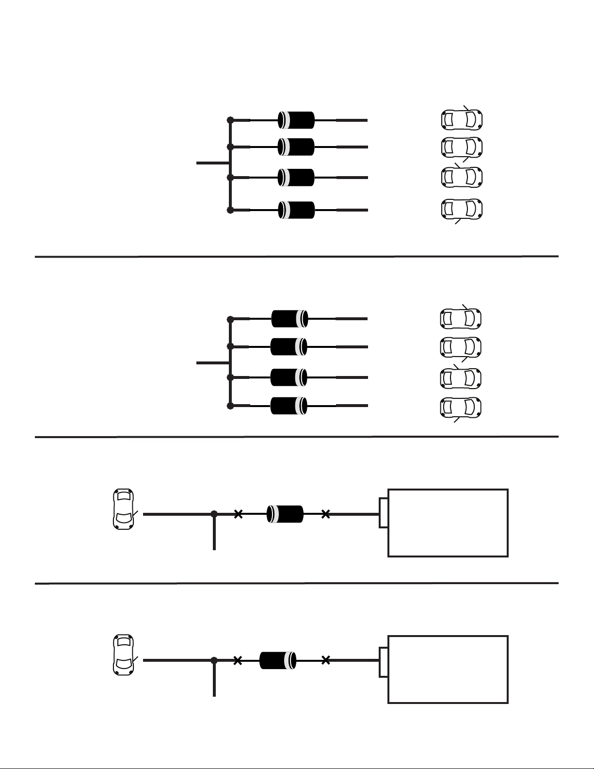
DIODE DIAGRAMS CONTINUED
MONITORING MULTIPLE WIRE POSITIVE (+) DOOR PINS
POSITIVE DOOR PIN TO MODULE (+)
MONITORING MULTIPLE WIRE NEGATIVE (-) DOOR PINS
FR DOOR PIN (+)
FL DOOR PIN (+)
RR DOOR PIN (+)
RL DOOR PIN (+)
FR DOOR PIN (-)
NEGATIVE DOOR PIN TO MODULE (-)
ISOLATING A NEGATIVE FALSING DOOR PIN WIRE FOR ALARM
NEGATIVE (-) DOOR PIN
TO NEGATIVE (-) DOOR INPUT ON ALARM
ISOLATING A POSITIVE FALSING DOOR PIN WIRE FOR ALARM
FL DOOR PIN (-)
RR DOOR PIN (-)
RL DOOR PIN (-)
BCM
POSITIVE (+) DOOR PIN
TO POSITIVE (+) DOOR INPUT ON ALARM
BCM

DIODE DIAGRAMS CONTINUED
MONITORING OPEN DOOR CIRCUIT FOR ALARM OR MANUAL TRANSMISSION (FORD, MAZDA)
(DIAGRAM COURTESY OF FORTIN ELECTRONICS)
FR DOOR PIN (OPEN)
FL DOOR PIN (OPEN)
BCM
OR
SJB
3K RESISTORS
12 VOLTS +
RR DOOR PIN (OPEN)
RL DOOR PIN (OPEN)
POSITIVE DOOR PIN TO MODULE (+)

PRIOR TO INSTALLATION
We recommend using a digital multi meter to test all wires in the vehicle as on-board computer systems can be
damaged by using low resistance testing devices including, test lights, and even computer safe test lights (logic
test probe). Notice Air Bag systems and do not disconnect these systems as it may turn on a “check air bag
system” light or code that may need a dealer scan tool to clear the fault.
We also recommend testing all functions of the vehicle such as power windows, locks, HVAC systems. Check
for any instrument cluster lights that are on such as “Check Engine”, “Air Bag”, “TPMS” lights. Also check
that all lights work on the vehicle such as brake lights, headlights, interior lights, etc. Also check the interior
and exterior for any damage including scuffs, dents, fingerprints, etc. Be sure to note all deficiencies or other
problems and make customer aware of these before starting the installation.
TESTING VEHICLE WIRES
WHEN LOOKING FOR A POSITIVE (+) WIRE CONNECT ONE LEAD OF YOUR MULTI METER TO A CHASSIS
GROUND.
WHEN LOOKING FOR A NEGATIVE (-) WIRE CONNECT ONE LEAD OF YOUR MULTI METER TO A 12V (+)
CONSTANT SOURCE
12 VOLTS (+) CONSTANT - You can find different locations for 12V(+) constant. You can use either the (+)
Battery Terminal or the (+) Constant feed to the ignition switch.
To test for this wire use multi meter set to DC Voltage with one lead to chassis ground and the other lead to
probe for a wire that reads between 10-16Volts (+) no matter the position of the key switch. This wire will also
be powering the locks, bypass modules and other circuits so we recommend you DO NOT remove or change
the supplied 30Amp Fuses on the 12V(+) Remote Starter wires. Connect the Red and Red/White wires on CN1
to this wire. If there are 2 12V(+) constant wires at the ignition switch, we recommend connecting the Red wire
from CN1 to one and the Red/White wire from CN1 to the other.
STARTER (+) - This wire provides a 12V(+) Source to the starter directly or to the starter circuit on the vehicle.
To test for this wire use a multi meter set to DC Voltage with one lead to chassis ground and the other lead to
probe for a wire that reads between 10-16Volts (+) when the key is in the Start (Crank) position in the key switch.
Connect the Purple wire on CN1 to this wire. If there are more than 1 starter wires on the vehicle then you can
use the Pink/White from CN1 and program for 2nd Starter in Menu 2-01 or use the Purple/Black on CN4 through
a Relay to power this wire. See relay guide.
STARTER (-) - This wire provides a Negative(-) Source to the starter circuit on the vehicle.
To test for this wire use a multi meter set to DC Voltage with one lead to 12V(+) Constant and the other lead to
probe for a wire that reads between 10-16Volts (-) when the key is in the Start (Crank) position in the key switch.
Connect the Purple/Black wire on CN4 to this wire.
ACCESSORY (+) - This wire provides a 12V(+) Source to the HVAC circuits on the vehicle.
To test for this wire use a multi meter set to DC Voltage with one lead to chassis ground and the other lead
to probe for a wire that reads between 10-16Volts (+) when the key is in the ACC and Run position in the key
switch. This wire will NOT show a positive feed in the Start (Crank) position. Connect the Orange wire on CN1
to this wire. If there are more than 1 starter wires on the vehicle then you can use the Pink/White from CN1 and
program for 2nd Accessory in Menu 2-01 or use the Orange/Black on CN4 through a Relay to power this wire.
See relay guide.
ACCESSORY (-) - This wire provides a Negative(-) Source to the HVAC circuits on the vehicle.
To test for this wire use a multi meter set to DC Voltage with one lead to 12V(+) Constant and the other lead to
probe for a wire that reads between 10-16Volts (-) when the key is in the ACC and Run position in the key switch.
This wire will NOT show a negative feed in the Start (Crank) position. Connect the Orange/Black wire on CN4 to
this wire

TESTING VEHICLE WIRES CONTINUED
WHEN LOOKING FOR A POSITIVE (+) WIRE CONNECT ONE LEAD OF YOUR MULTI METER TO A CHASSIS
GROUND.
WHEN LOOKING FOR A NEGATIVE (-) WIRE CONNECT ONE LEAD OF YOUR MULTI METER TO A 12V (+)
CONSTANT SOURCE
IGNITION (+) - This wire provides a 12V(+) Source to the Ignition circuit on the vehicle.
To test for this wire use a multi meter set to DC Voltage with one lead to chassis ground and the other lead to
probe for a wire that reads between 10-16Volts (+) when the key is in the run and STAYS ON during Start (Crank)
position in the key switch. Connect the Pink wire on CN1 to this wire. If there are more than 1 starter wires on
the vehicle then you can use the Pink/White from CN1 and program for 2nd Ignition in Menu 2-01 or use the
Pink/Black on CN3 through a Relay to power this wire. See relay guide.
IGNITION (-) - This wire provides a Negative(-) Source to the Ignition circuit on the vehicle.
To test for this wire use a multi meter set to DC Voltage with one lead to 12V(+) Constant and the other lead to
probe for a wire that reads between 10-16Volts (-) when the key is in the Run position and STAYS ON during Start
(Crank) position in the key switch. Connect the Pink/Black wire on CN4 to this wire.
PARK LIGHTS (+) - This wire will usually be found at the park light switch but on most vehicles can be found at
the Fuse Box or Driver’s Kick panel. To test for this wire use a multi meter set to DC Voltage with one lead to
chassis ground and the other lead to probe for a wire that reads between 10-16Volts (+) when just the park lights
are turned on by the switch. If there is more than 1 park light wire on the vehicle you can isolate them by using 2
6 amp diodes or relays. See Diode and/or Relay Guide for installation.
PARK LIGHTS (-) - This wire will usually be found at the park light switch.
To test for this wire use a multi meter set to DC Voltage with one lead to 12V(+) Constant and the other lead to
probe for a wire that reads between 10-16Volts (-) when just the park lights are turned on by the switch. Connect
the White/Black wire on CN4 to this wire to. It may be possible that a negative park light wire be Multiplexed. In
this case please refer to the Relay Diagram for installation.
HORN (-) - This wire will be usually found at the clock spring or in the harness coming from the steering wheel.
To test for this wire use a multi meter set to DC Voltage with one lead to 12V(+) Constant and the other lead to
probe for a wire that reads between 10-16Volts (-) when the horn is on, it will most likely rest at 12V (+). Connect
the Brown/Black wire on CN4 to this wire. It is possible that some vehicles may need a shorter or longer timing
output to sound the horn. The timing of the pulsed output on this wire can be adjusted in Menu 3-08
DISARM AND REARM (-) -Test the vehicle for a OEM Content Alarm System (Factory Alarm). There a number of
ways to test if the vehicle has a OEM Alarm System.
1. Sit in the vehicle with all doors shut and press lock on the OEM Keyless remote, or
With the door open press lock on the door panel lock switch and shut the door, or
Shut the door and turn the key in the lock key cylinder on the exterior of the door.
2. Wait approximately 1 minute then manually unlock the door and open. If the horn starts to sound then
the vehicle has a OEM Alarm System and proceed to Step 2. If there is no horn honks then the vehicle is not
equipped with an OEM Alarm System and you can move on to testing wires
3. To shut off the alarm follow this sequence, turn the key to the unlock position in the door cylinder. If the
horn stops honking then this is the way to disarm the OEM Alarm System, if this doesn’t work then try,
Starting the vehicle by key, if the horn stops honking then this is the way to disarm the OEM
Alarm System, if this doesn’t work then try,
Pressing unlock on the OEM Keyless Remote, if the horn stops honking then this
is how to disarm the OEM Alarm System

TESTING VEHICLE WIRES CONTINUED
WHEN LOOKING FOR A POSITIVE (+) WIRE CONNECT ONE LEAD OF YOUR MULTI METER TO A CHASSIS
GROUND.
WHEN LOOKING FOR A NEGATIVE (-) WIRE CONNECT ONE LEAD OF YOUR MULTI METER TO A 12V (+)
CONSTANT SOURCE
DISARM (-) - Refer to Step 3 of Testing for Alarm.
If it disarms by the key in the door cylinder then find the wire that duplicates this.
To test for this wire use a multi meter set to DC Voltage with one lead to 12V(+) Constant and the other lead
to probe for a wire that reads between 10-16Volts (-) when the key is turned to the unlock position in the door
cylinder. Connect the Blue/White wire on CN3 to this wire.
In the case the vehicle needs to be started to disarm the alarm please program special disarm options in Menu
1-06 to option 2. Whenever unlock is pressed the remote starter will automatically simulate turning the ignition
on for 1 second, in turn disarming the OEM Alarm system. No extra wire connections are required for this type.
It is also possible that the OEM Alarm can only be disarmed by the factory OEM Keyless remote. In this case
please check for bypass module compatibility.
REARM (-) - Refer to Step 1 of Testing for Alarm.
If it rearms by the key in the door cylinder then find the wire that duplicates this.
To test for this wire use a multi meter set to DC Voltage with one lead to 12V(+) Constant and the other lead to
probe for a wire that reads between 10-16Volts (-) when the key is turned to the lock position in the door cylinder.
Connect the Green/White wire on CN3 to this wire.
In the case the vehicle needs have the door open while pressing lock on the door panel switch please refer to
finding a door pin wire in this part of the guide and connect the wire accordingly.
TACHOMETER OR RPM (AC) - There are multiple locations to get a tach signal. Most common is either at an
ignition coil or fuel injector. Other locations include camshaft or crank position sensor, and the instrument
cluster, At either a coil or an injector there most likely will be an uncommon wire color across all of them.
To test this wire START THE VEHICLE and use a multi meter set to AC Voltage with one lead to chassis ground
and the other lead to probe for a wire that will read between 1-6Volts and will normally change with increase and
decrease of engine RPM. Connect the Purple/White wire on CN3 to this wire.
Solace remote starters also have the capability of running in tachless mode where there is no connection
required to monitor if the vehicle is running or not. Please refer to the Tach Learning procedure for more
information.
BRAKE SWITCH (-) - This wire can usually always be found at the brake switch but on most vehicles can be
found at the fuse box or Driver’s Kick Panel.
To test for this wire use a multi meter set to DC Voltage with one lead to chassis ground and the other lead to
probe for a wire that reads between 10-16Volts (+) when the foot brake is depressed and neutral or negative
when the brake is not depressed. Connect the Pink wire on CN3 to this wire.
PARK BRAKE(-) - This wire can usually always be found at the emergency brake switch or at the instrument
cluster. On some vehicles it can also be found at the Daytime Running Light module behind the dash.
To test for this wire use a multi meter set to DC Voltage with one lead to 12V(+) Constant and the other lead to
probe for a wire that reads between 10-16Volts (-) when the park brake is engaged and neutral or negative when
the park brake is not engaged. *NOTE some vehicles may have to be running to test this wire properly. Connect
the Black/White wire on CN3 to this wire.

TESTING VEHICLE WIRES CONTINUED
WHEN LOOKING FOR A POSITIVE (+) WIRE CONNECT ONE LEAD OF YOUR MULTI METER TO A CHASSIS
GROUND.
WHEN LOOKING FOR A NEGATIVE (-) WIRE CONNECT ONE LEAD OF YOUR MULTI METER TO A 12V (+)
CONSTANT SOURCE
TRUNK RELEASE (-) - This wire can usually always be found at the trunk release switch.
To test for this wire use a multi meter set to DC Voltage with one lead to 12V(+) Constant and the other lead to
probe for a wire that reads between 10-16Volts (-) when the trunk release is engaged. Connect this wire to the
Red/White wire on CN4. The output time can be adjusted in Menu 1-09
TRUNK RELEASE (+) - This wire is usually coming from the BCM and is controlled from the factory keyless entry
remote.
To test for this wire use a multi meter set to DC Voltage with one lead to chassis ground and the other lead to
probe for a wire that reads between 10-16Volts (+) when the trunk release is engaged. We recommend that
when connecting trunk in this way to isolate the switch with a relay. See Relay Guide. If the trunk release is (+)
directly from a trunk release switch then you can connect this wire to the Pink/White wire on CN1 and program
for Positive Trunk in Menu 2-01.
WAIT TO START/GLOW PLUG LIGHT (+/-) - This wire can usually always be found at the instrument cluster or at
the ECM.
To test for this wire use a multi meter set to DC Voltage with one lead to 12V(+) Constant and the other lead to
probe for a wire that reads between 10-16Volts (-) with the ignition switch turned on and the Wait to Start bulb is
on. Once the Wait to Start Bulb goes out and the meter no longer reads 12V(-) this is a Negative (-) Wait to Start
Wire. If the Wait to Start wire reads 12V(-) when the light goes out then this wire is Positive (+). Connect this
wire to the Gray/Black wire on CN4. You can also set a desired Time delay in Menu 2-04
DOOR PIN (-) - This wire can usually always be found at the door pin switch and can usually be found at the BCM
or at the instrument cluster.
To test for this wire use a multi meter set to DC Voltage with one lead to 12V(+) Constant and the other lead to
probe for the door pin wire. If the wire reads between 10-16Volts (-) when the door is open then the door pin is
negative (-) and you can connect the Green wire on CN4 to this wire.
DOOR PIN (+) - This wire can usually always be found at the door pin switch and can usually be found at the
BCM or at the instrument cluster.
To test for this wire use a multi meter set to DC Voltage with one lead to Chassis Ground and the other lead to
probe for the door pin wire. If the wire reads between 10-16Volts (+) when the door is open then the door pin is
positive (+) and you can connect the Purple wire on CN4 to this wire.
DOOR PIN (OPEN) - This wire can always be found at the door pin switch and can usually be found at the BCM
or at the instrument cluster.
To test for this wire use a multi meter set to DC Voltage with one lead to Chassis Ground and the other lead to
probe for the door pin wire. If the wire reads between 2-7 Volts when the door is open and nothing when it is
closed then the door pin is an open circuit and you need to follow the OPEN DOOR CIRCUIT DIAGRAM in the
DIODE GUIDE and connect the (+) wire to the Purple Wire on CN4.
*If connecting to circuit with a delay you can set the desired delay time in Menu 3-02.
**Also be sure to check that all doors are monitored and there are multiple wires please isolate with diodes.
Please see DIODE GUIDE for install.
***For Rearm Situations when a door needs to be opened you can connect the Green/White wire on CN4 directly
to a Negative (-) door pin, or to a relay to switch to a positive for a Positive (+) door pin, or use the Green/White
wire on CN4 to cut the wire with a relay for Open Door circuit. Please refer to RELAY GUIDE for installation.
****All doors must be connected when installing into a MANUAL TRANSMISSION VEHICLE

TESTING VEHICLE WIRES CONTINUED
WHEN LOOKING FOR A POSITIVE (+) WIRE CONNECT ONE LEAD OF YOUR MULTI METER TO A CHASSIS
GROUND.
WHEN LOOKING FOR A NEGATIVE (-) WIRE CONNECT ONE LEAD OF YOUR MULTI METER TO A 12V (+)
CONSTANT SOURCE
HOOD SWITCH (-) - This wire is usually connected to the supplied Pin Switch with each starter. In the case that
a vehicle has an OEM hood switch that is negative (-) this can be connected instead of the Pin Switch.
To test for this wire use a multi meter set to DC Voltage with one lead to 12V(+) Constant and the other lead to
probe for a wire that reads between 10-16Volts (-) when the hood switch is open. Connect this wire to the Gray/
White wire on CN4.
AUXILIARIES (SLIDING DOORS, ETC.) (-) - This wire can usually always be found at the desired auxiliary
release switch.
To test for this wire use a multi meter set to DC Voltage with one lead to 12V(+) Constant and the other lead to
probe for a wire that reads between 10-16Volts (-) when the auxiliary switch is engaged. Connect this wire to the
any of the following wires on CN4, Black/Brown for AUX 1 Control from remote, Black/Green for AUX 2 Control
from remote, Black/Blue for AUX 3 Control from remote, Black/Yellow for AUX 4 Control from remote. These
wires can be also control multiple other functions like sunroof open/close, window roll up/down, gas traps,
etc. Test these wires the same as testing for Auxiliary sliding controls. **Please Note that only AUX 1 and 2 are
controllable from all 1-Way remotes, AUX 3 and 4 are only controllable from the 2-Way LCD remote. The output
times and function control can also be controlled from Menu 4-9 to 4-16
LOCK (-) - This wire can usually always be found at the door panel lock/unlock switch, and on most cars at the
BCM. It is becoming more popular that locks can be controlled using a bypass module.
To test for this wire use a multi meter set to DC Voltage with one lead to 12V(+) Constant and the other lead to
probe for a wire that reads between 10-16Volts (-) when the lock button is pressed. Connect the Green wire on
CN2 to this wire. There are multiple changes that can be made to the way this wire functions in Menu 1-01 to
1-05.
UNLOCK (-) - This wire can usually always be found at the door panel lock/unlock switch, and on most cars at
the BCM. It is becoming more popular that locks can be controlled using a bypass module.
To test for this wire use a multi meter set to DC Voltage with one lead to 12V(+) Constant and the other lead to
probe for a wire that reads between 10-16Volts (-) when the unlock button is pressed. Connect the Blue wire on
CN2 to this wire. There are multiple changes that can be made to the way this wire functions in Menu 1-01 to
1-05.
**For Positive, Reverse Polarity, and Resistance Lock or Unlock, or adding Door Lock Actuators please see the
Relay Guide for Install.
BYPASS MODULE - It is getting more and more popular that vehicles functions can be controlled by bypass
modules. The features can include some or all of the following. Lock, Unlock, Alarm Arm, Alarm Disarm, Tach,
Foot Brake Status, Emergency Brake Status, Ignition Status, Hood Status, Door Status, Trunk Status, Trunk
Release, Auxiliary Outputs, Ignition Output, Start Output, Accessory Output, Park Light Output, Horn Output,
Window Roll Up/Down, and more. These wires can be hard wired directly from the bypass module to the remote
starter module saving time. When using a bypass module with 2-Way communication most of these wires do
not need to be connected, in 1-Way communication some wires may be connected. Please see installation guide
of bypass module for more information. Solace is both 2-Way and 1-Way Data Compatible for both Fortin and
iDatalink bypass modules.

VEHICLE INSPECTION SHEET
INVOICE #: ______________________
MAKE: __________________________
DATE: _________________
MODEL: _______________ YEAR: __________
STARTER: _______________________ DROP OFF: ____________
INSTALL OPTIONS:
STARTER
STARTER/ALARM
ALARM ONLY
AUTOMATIC TRANS
MANUAL TRANS
TRANSPONDER
DIESEL
OEM ALARM
TRUNK RELEASE
LOCK
UNLOCK
AUX 1
AUX 2
AUX 3
DEFROST
HEATED SEATS
TRUNK PIN
AUX ALARM SENSORS
AC200/200 GPS
BYPASS:
PICK UP: __________
AUX 4
_______________
_______________
_______________
OTHER INSTALL NOTES:
VEHICLE NOTES AND DAMAGE:
CHECK IN OUT
PWR WINDOWS
PWR LOCKS
WIPERS
PWR TRUNK
PARK LIGHTS
HEADLIGHTS
TURN SIGNALS
BRAKE LIGHTS
PWR/HEAT SEATS
REAR DEFROST
CHECK IN OUT
HORN
LIGHTER
CRUISE
SWC
RADIO
MAINTENANCE
NOTES:
MARK DAMAGES
WITH AN “X”
HAZARD LIGHTS
DASH LIGHTS
DOMELIGHT
HEATER + A/C
SERV. BATTERY
SERV. AIR BAG
SERV. ABS
SERV. ENGINE
CUSTOMER SIGNATURE:
DATE: INSTALLER:


Solace Technologies Limited
17302 - 116 Ave Edmonton, AB T5S - 2X2
p: 780.443.4379 tf:1.855.SOLACE5
f: 780.443.4137 tff: 1.855.SOLACE6
www.SolaceRemoteStarters.com
 Loading...