

Page 1

USER GUIDE
ups520 Rackmount
750 VA, 1050 VA, 1425 VA, and 2250 VA
A Company
Page 2

Important Notice
The UPS ground (earth) conductor carries leakage current from the loads in addition to any
leakage current generated by the UPS. This UPS generates no more than 1 mA of current. To
limit the total leakage current to 3.5 mA, the load leakage must be limited to 2.5 mA. The threewire receptacle that you plug the UPS into must have a good (low-impedance) ground (protective earth) connection to provide a safe path for leakage current.
Page 3
u p s 5 2 0
®
Rackmount
750 VA, 1050 VA, 1425 VA and 2250 VA
User Guide
STM-0405A
© Copyright 1998, Best Power. All rights reserved.
A
Company
Page 4

If You Have a Question
Customer Support
If you have a question or problem, Table 3, Troubleshooting, may help. If you need more help,
please have your UPS model number and serial number (on the back label) nearby, and
call the SOLA office nearest you (see the SOLA offices section).SOLA’s service technicians
have in-depth knowledge of the UPS and poser problems.
SOLA may tell you the UPS must be returned. If this happens, we will give you a Return
Authorisation (RA) number. When you return a SOLA 520 Rackmount to the factory for any
reason, please use the original packing material in which your unit was shipped to you. You
may be responsible for repair charges for damaged units which are not packed in SOLA
packing material.If you have discarded the original packing material, please call the nearest
SOLA office so that we can ship new packing material to you. If you have any questions, please
feel free to call or fax the nearest SOLA office. Please do not return your SOLA 520 Rackmount
without calling SOLA first. SOLA will advise you where to ship your SOLA520 Rackmount.
SOLA reserves the right to change specifications without prior notice.
Page 5
1
SOLA Never Stops Innovating
Table of Contents
Safety Instructions . . . . . . . . . . . . . . . . . . . . . . . . . . . . . . . . . . . . . . . . . . . . . . . . . . . .2
UPS Features . . . . . . . . . . . . . . . . . . . . . . . . . . . . . . . . . . . . . . . . . . . . . . . . . . . . . . . .3
Rack Installation . . . . . . . . . . . . . . . . . . . . . . . . . . . . . . . . . . . . . . . . . . . . . . . . . . . . . .5
Quick Startup . . . . . . . . . . . . . . . . . . . . . . . . . . . . . . . . . . . . . . . . . . . . . . . . . . . . . . . .6
Symbols, LEDs and Audible Beeps . . . . . . . . . . . . . . . . . . . . . . . . . . . . . . . . . . . . . . . .7
Installing CheckUPS IISoftware . . . . . . . . . . . . . . . . . . . . . . . . . . . . . . . . . . . . . . . . . .9
BestDock™ . . . . . . . . . . . . . . . . . . . . . . . . . . . . . . . . . . . . . . . . . . . . . . . . . . . . . . . . .9
Troubleshooting . . . . . . . . . . . . . . . . . . . . . . . . . . . . . . . . . . . . . . . . . . . . . . . . . . . . .10
Replacing the Batteries . . . . . . . . . . . . . . . . . . . . . . . . . . . . . . . . . . . . . . . . . . . . . . . .11
Battery Replacement Instructions . . . . . . . . . . . . . . . . . . . . . . . . . . . . . . . . . . . . .12
Communication Port . . . . . . . . . . . . . . . . . . . . . . . . . . . . . . . . . . . . . . . . . . . . . . . . . .13
DB-9 Pinouts . . . . . . . . . . . . . . . . . . . . . . . . . . . . . . . . . . . . . . . . . . . . . . . . . . . .14
Specifications . . . . . . . . . . . . . . . . . . . . . . . . . . . . . . . . . . . . . . . . . . . . . . . . . . . . . . .14
Appendix A: Adjusting Voltage Settings . . . . . . . . . . . . . . . . . . . . . . . . . . . . . . . . . . .16
Warranty . . . . . . . . . . . . . . . . . . . . . . . . . . . . . . . . . . . . . . . . . . . . . . . . . . . . . . . . . . .18
SOLA Australia Offices . . . . . . . . . . . . . . . . . . . . . . . . . . . . . . . . . . . . . . . . . . . . . . .19
SOLA/Best Offices . . . . . . . . . . . . . . . . . . . . . . . . . . . . . . . . . . . . . . . . . . . . . . . . . . .20
Trademarks
Windows is a registered trademark of Microsoft Corporation.
All other brand and product names are trademarks or registered trademarks of their respective
holders.
Page 6
2
SOLA Never Stops Innovating
Safety Instructions
IMPORTANT SAFETY INSTRUCTIONS!
SAVE THESE INSTRUCTIONS!
This User Guide contains important instructions for your SOLA520 Rackmount that must be followed during installation and maintenance of the UPS and batteries.
The installation and use of this product must comply with all national, federal, state, municipal,
or local codes that apply. For assistance, call SOLAService or your local SOLA office.
If the SOLA unit has been damaged during shipment, call your vendor immediately.
If the SOLA unit is stored, the batteries should be recharged every 6 months. If stored above
25°Celsius, recharge the batteries more often.
CAUTION!
Whenever the SOLA520 Rackmount is “On,” there may be dangerous voltage present at the
unit’s outlets. This is true because the unit’s battery supplies power even if the unit is not
plugged into the wall outlet. The unit contains dangerous voltages.
To reduce the risk of electric shock, install in a temperature-controlled and humiditycontrolled indoor area free of conductive contaminants.
The power supply cord is intended to serve as the disconnect device. The socket-outlet shall
be near the equipment and shall be easily accessible.
With the exception of the user-replaceable batteries, all servicing of this equipment must be
performed by qualified service personnel.
Before maintenance or repair, all connections must be removed. Before maintenance, repair,
or shipment, the unit must be completely switched off and unplugged or disconnected.
Page 7
3
SOLA Never Stops Innovating
SOLA520 Rackmount Controls
and Indicators
UPS Features
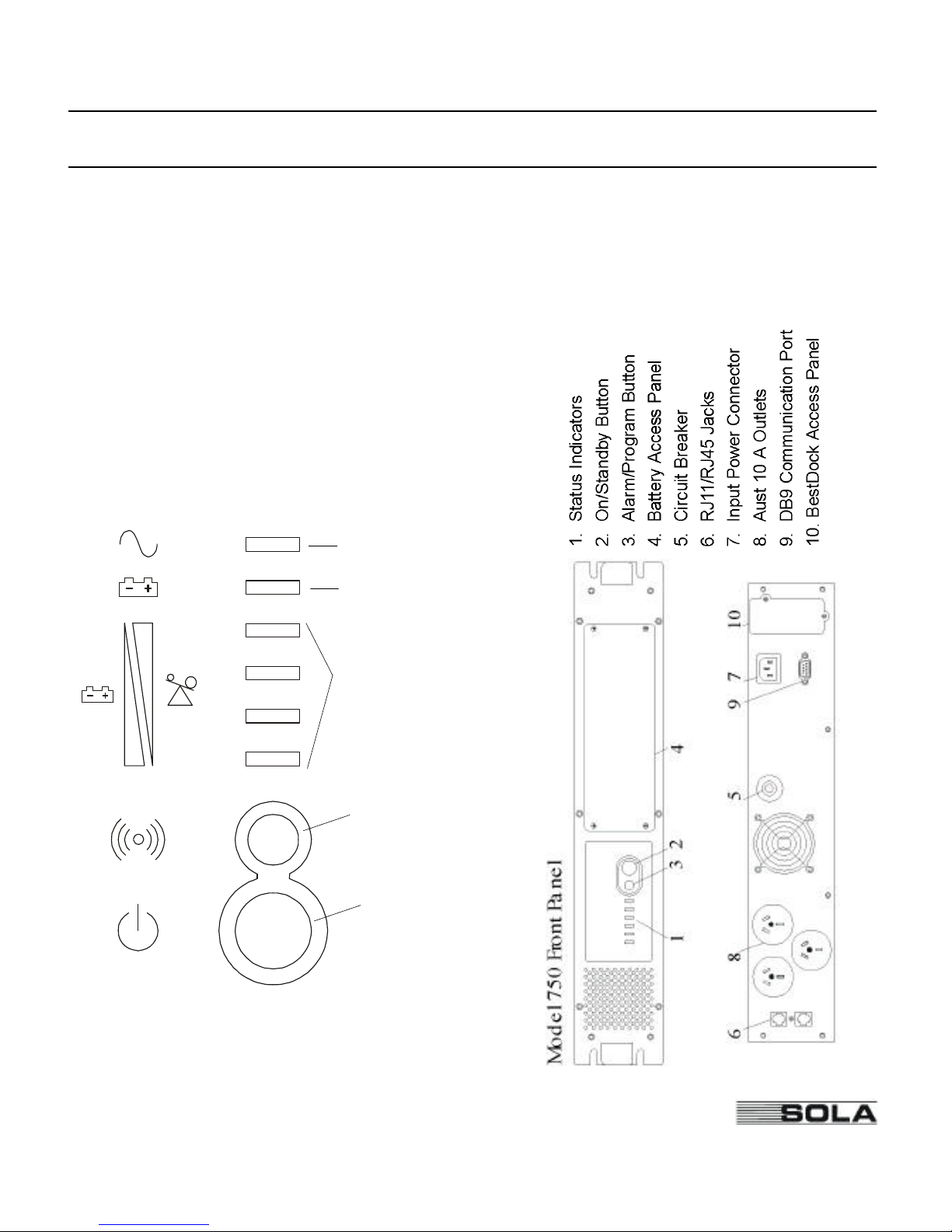
The SOLA 520 Rackmount provides protection against power problems, including power outages, brownouts, and sudden increases in power. It also provides spike suppression and line noise
filtering to protect your equipment. Front panel LEDs and an audible alarm keep you aware of
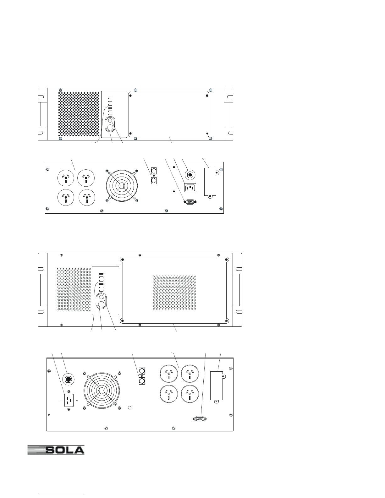
the unit’s status. Use the drawings on this and the following page to identify features of the unit.
Line/Buck-boost
Battery Power
% Load or
Battery Charge
(see page 7)
Alarm/Program
Button
On/Standby
Button
(D)
(C)
(B)
(A)
Page 8
1 2 3 4
7 568
9
10
Model 2250 Front Panel
1
2 3
4
8
6
9 7 5
10
Model 1050 and 1425 Front Panel
4
SOLA Never Stops Innovating
1. Status Indicators
2. On/Standby Button
3. Alarm/Program Button
4. Battery Access Panel
5. Circuit Breaker
6. RJ11/RJ45 Jacks
7. Input Power Connector
8. Aust 10 A Outlets
9. DB9 Communication Port
10. BestDock Access Panel
8
Page 9
5
SOLA Never Stops Innovating
Rack Installation
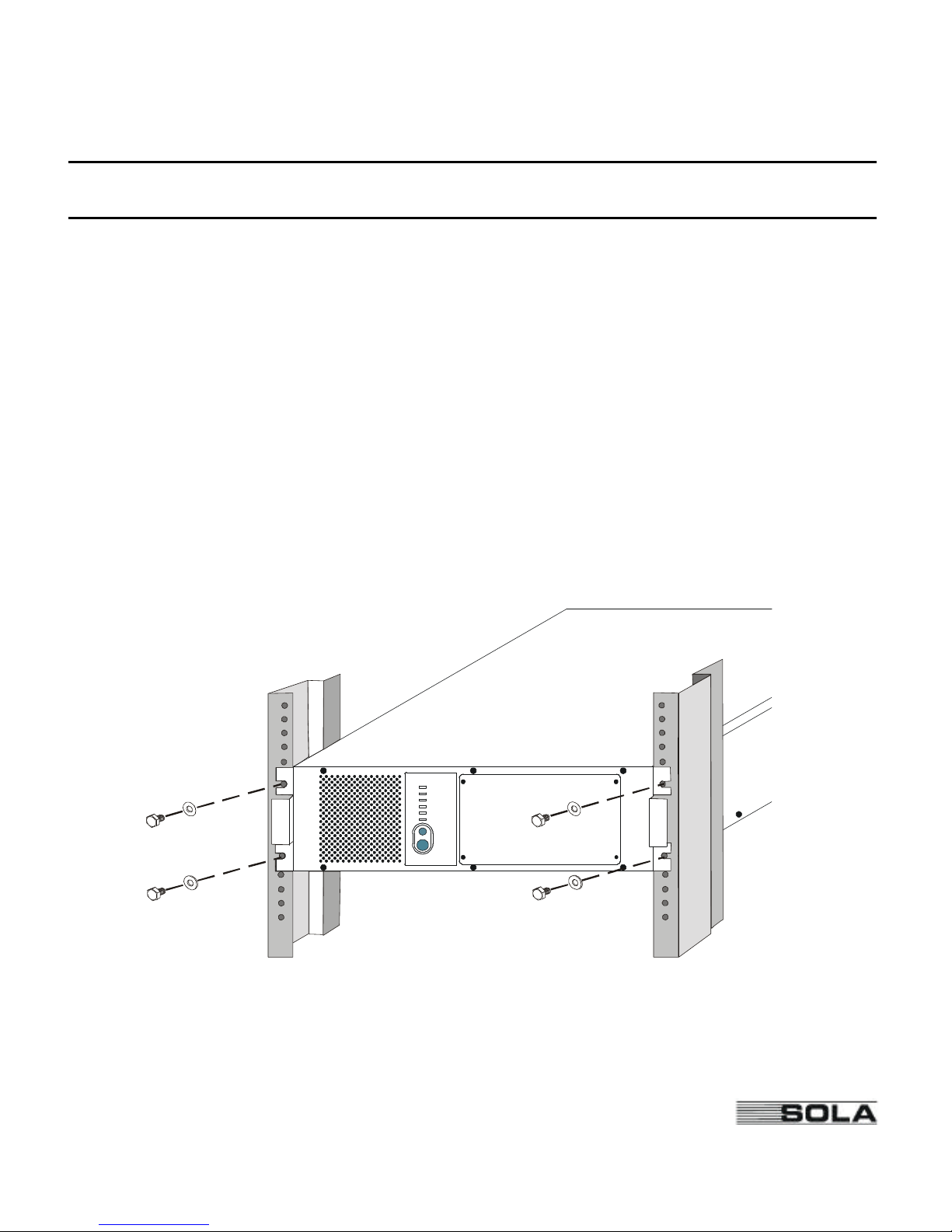
Mount the SOLA 520 Rackmount in a 19-inch (483-mm) EIA 310 C standard rack.
Do not try to mount the unit if the rack is too wide.
Do not rely on the front mountings only to support the weight of the unit.
Install a stationary shelf or supporting angle brackets (available as standard rack hardware from
electronics distributors) below the intended rack location for the SOLA520 Rackmount. Secure
the shelf or brackets at both the front and back of the rack using bolts, nuts, and washers.
Carefully lift the unit onto the shelf or brackets and slide it into the rack as shown below. The
mounting holes on the sides of the front panel should match the holes in the rack.
Use bolts and washers to attach the unit securely to the rack.
Page 10
6
SOLA Never Stops Innovating
Quick Startup
1
Your SOLA520 Rackmount UPS has a removable power cord. Connect the power cord to
the back of the unit and plug the UPS into a wall outlet.
2
Let the unit charge the battery for at least 3 hours (7 hours for 1425 VA model if it is fully
loaded). You may use the unit while the battery charges, but the battery backup runtime will
be reduced until the battery is fully charged.
3
Start the SOLA520 Rackmount by pressing and holding the On/Standby button (large
button in the center of the front panel) in for about one second. Note: To turn the unit either
on or off, the On/Standby button must be pressed for about one second.
3.a.When it starts, the unit beeps and lights the front panel lights, turns them off, and lights
them again. Next, the SOLA520 Rackmount applies AC output to the back panel
receptacles.It does a brief self test, turning various front panel lights off and on.
3.b.After 30 seconds or less, the self test is complete. The top and bottom green lights will
come on and remain on. If the unit beeps, or if the top light does not remain on even
though input power is available from the wall outlet, go to the Troubleshooting section.
4
Switch off the equipment you want to protect, and plug each load into the outlets on the
back of the SOLA520 Rackmount.
5
Switch on the protected equipment, one load at a time. If the UPS beeps an alarm when you
start your equipment, the UPS may be overloaded. See the Troubleshooting section.
The bottom four lights on the front of the UPS show the % of load capacity that your equipment is using. See Symbols, LEDs and Audible Beeps Section for more information.
6
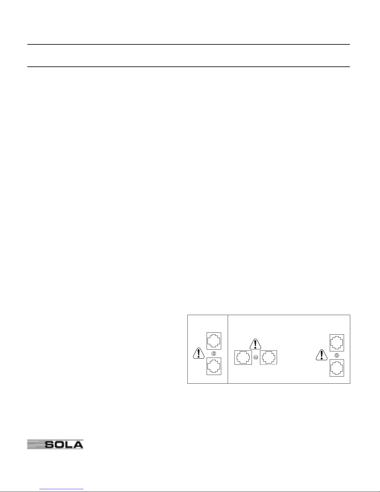
The RJ-11 or RJ-45 Surge Protection
jacks will protect equipment that uses
an RJ-11 or RJ-45 connection. Plug
the 10BASE-T network connection
into the surge protection jack labeled
“IN” on the back of the SOLA520
Rackmount. Plug the protected equipment into the surge protection jack
labeled “OUT.” Network cabling is not
provided. This connection is optional. It is not needed to use the SOLA520 Rackmount.
7
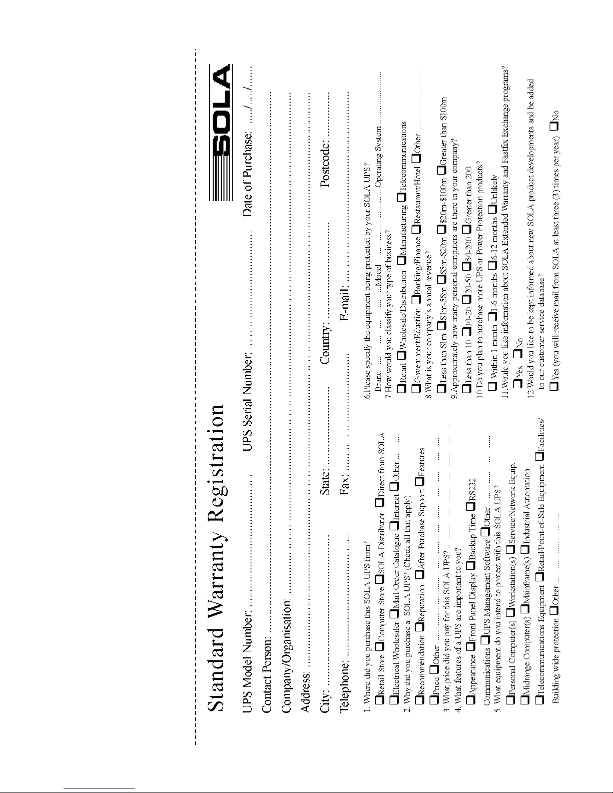
Please fill out the warranty registration card and return it to your local SOLA office.
OUTIN
OUT
IN
750
IN
OUT
1050, 1425 & 2250
OR
RJ-11 or RJ-45 Jacks
Page 11
7
SOLA Never Stops Innovating
Symbols, LEDs and Audible Beeps
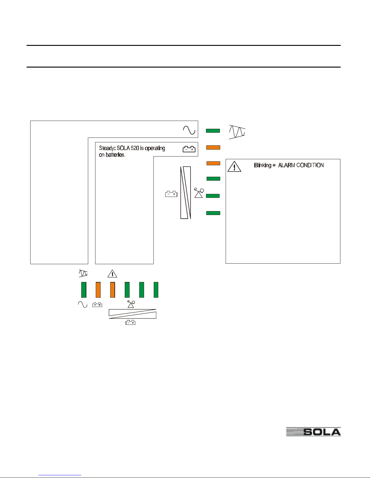
The front panel indicators (LEDs) and an audible beep indicate the unit status. The unit beeps
whenever the unit is on battery power or an alarm is present. See Table 2 for information about
beep coding. In the figure below, bucking means that SOLA520 Rackmount is reducing high
input voltage, and boosting means SOLA 520 Rackmount is increasing low input voltage.
If your SOLA520 Rackmount runs on batteries frequently because the input utility line varies
often, you may want to adjust your SOLA520 Rackmount to accept wider voltage variations
before switching to batteries. Appendix A describes how to adjust the SOLA520 Rackmount
from the front panel in response to specific utility power problems. You should have an
electrician check your nominal line voltage and determine if the problem is due to a “Surge”
(high) voltage or “Brownout” (low) voltage. Changing the setting without this knowledge could
make the problem worse.
Steady: SOLA 520 is operating on AC line.
Blinking: SOLA 520 is bucking or boosting input AC line.
A
B
C
D
A, B, C, and D indicate
battery charge:
A, B, C & D = 75-100 %
B, C & D = 50-75 %
C & D = 25-50 %
D = 0-25 %; if D flashes,
less than 2 minutes
of runtime remain.
A, B, C, and D indicate
per cent of full load:
A, B, C, & D = 75-100%
A, B, & C = 50-75%
A & B = 25-50%
A = 0-25%
A, B, C, & D, with D
flashing, load = 110%
or higher.
A = UPS Fault; Fan Fail or Overcharge
C = UPS shutdown due to output overload.
B = UPS failed the battery test.
B & C = UPS shutdown from communication
at RS-232, remote shutdown or SNMP.
A & B = UPS shutdown due to main relay
failure or short circuit on output.
A & C = UPS over-temperature shut down.
D
C B
A
750 model
1050, 1425
and 2250
models
(1050, 1425,
and 2250
models only)
(750 model
only)
Page 12
8
SOLA Never Stops Innovating
To silence an alarm, press the Alarm/Program button on the front panel. The beep will stop, but
the alarm light will stay on. Note: Silencing the alarm does not solve the problem that caused it.
See Tables 2 and 3.
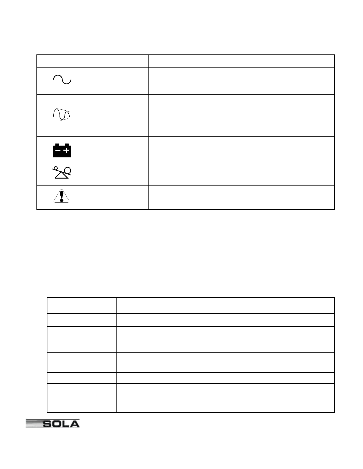
Symbols and LEDs What It Means
Steady:Acceptable input power is present. The unit is
running on line power.
Off:No input power is present or the unit is switched off.
The unit is running on battery power.
Output Overload:Refer to Tables 2 and 3.
Replace the Batteryor UPS Fault.Refer to Tables 2 and 3.
Blinking:The unit is boosting or bucking utility power.
Boost= Automatically increases low input power to prevent
the unit from switching to battery.
Buck= Automatically decreases high input power to prevent
the unit from switching to battery.
Table 1: Symbols and LEDs
AC LINE
(Green)
LINE CORRECTION
(Green)
BATTERY MODE
(Yellow)
OVERLOAD, (D LED)
(Yellow)
WARNING, (D LED)
(Yellow)
Number of Beeps What It Means
1 every 10 seconds Line Loss:The unit is on battery power. See Table 3for more information.
2 every 10 seconds
Low Battery Alarm:The unit was running on battery power and shut down due
to very low battery voltage. The unit will restart automatically when acceptable
power returns.
Continuous
1) Output Short Circuit
2) Starting Fault:Input voltage out of range when unit is turned on.
3) UPSFault:UPSinternal failure.
1 beep every second Output Overload:Too much load equipment.
3 every 5 minutes
Replace the Battery: The battery needs to be replaced. See “Replacing the
Batteries” on page 10.
Table 2: Audible Beeps
Page 13
9
SOLA Never Stops Innovating
Installing CheckUPS II Software
Your UPSis supplied with a CD-ROM and communication cable to install and operate
CheckUPSII power management software. To install CheckUPSII on your computer, follow the
instructions enclosed with the CD-ROM.
BestDock
TM
The SOLA520 Rackmount BestDock communication slot accepts optional communication
cards, like the internal BestLink SNMP/WEB adapter. The insertion of a card into the BestDock
communication slot replaces the normal communication channel from the SOLA520 Rackmount
DB-9 Communication Port. The DB-9 port becomes the connection point for configuring the
card in the BestDock.
Page 14
10
SOLA Never Stops Innovating
Troubleshooting
If you have a question or problem, the troubleshooting table may help. (See Table 3.) If you need
assistance, phone SOLA Service or your local SOLAoffice. Please have the model number and
serial number (located on the rear of the unit) available.
If the unit must be returned, SOLA will give you a Return Authorisation (RA) number. Phone
SOLA for an RA number before returning the unit for any reason.
Problem Possible Reasons What To Do
Yellow WARNINGLED on,
Green LINELED on,
three beeps every five minutes.
Unit has failed the battery
test
Turn the unit off and then on to reset
the “Replace Battery” alarm and LEDs.
Replace the batteries. See “Replacing
the Batteries” on page 10.
Yellow BATTERYLED on,
Green LINELED off,
one beep every 10seconds.
1. Utility power outage.
2. Loose plug.
3. Tripped circuit breaker.
4. Power cord failure.
1. Wait for power to return.
2. Make sure the power cord is
connected.
3. Reset the circuit breaker.
4. Phone SOLA Service.
Green LINELED flashes. Input voltage is high or
low.
Nothing. The UPS is correcting the input
voltage. You may require an electrician
to investigate the reason for the input
voltage deviation.
Yellow BATTERYLED on,
Green LINELED off,
two beeps every 10 seconds.
Very low battery voltage. Plug the unit into a working wall outlet
for at least 8 hours to allow the batteries
to charge. After recharge, if the SOLA
520 Rackmount will not operate on batteries, or it beeps twice every 10 seconds
on batteries, phone SOLA Service.
Yellow OVERLOADLED on,
one beep every second.
The power required by the
equipment is too high.
1. Remove load equipment.
2. Reduce load level until the beeping
stops.
Yellow WARNINGLED on.
Continuous beep.
1. Output short circuit.
2. UPS Fault
1. Remove load and reset UPS.
2. Phone SOLA Service.
Table 3: Troubleshooting
Page 15
11
SOLA Never Stops Innovating
Replacing the Batteries
The SOLA520 Rackmount batteries are user-replaceable and can be replaced while the SOLA
520 Rackmount has AC input applied and powers the loads. This means that, if necessary, you
can replace the batteries while the UPS is running. Before you replace the batteries, make sure
that you read the safety information below.
Note: If you have a power outage while you are replacing the batteries, the UPS will not be
able to run on battery power and your protected equipment will shut down.
CAUTION!
The batteries used in the UPS and battery pack can produce dangerous voltage and high
current. Therefore, the batteries may cause severe injury if their terminals contact a tool or the
UPS cabinet. Be very careful to avoid electrical shock and burns from contacting terminals
while you replace the batteries.
Batteries contain caustic acids and toxic materials and can rupture or leak if mistreated.
Remove rings and metal wristwatches or other jewelry. Do not carry metal objects in your
pockets: these objects could fall into the UPS.
Never allow any tool to contact both a battery terminal and the UPS cabinet or another
battery terminal. Do not lay tools or metal parts on top of batteries.
To ensure continued superior performance of your UPS and to maintain proper charger
operation, you must replace the UPS batteries with the same number and type of batteries.
These batteries must be the same type as the original batteries: valve-regulated, low
maintenance. The replacement batteries should have the same voltage and ampere-hour rating
as the original batteries.
Assume that old batteries are fully charged. Use the same precautions you would use when
handling a new battery. Do not short battery terminals with a cable or tool! Batteries contain
lead. Many areas have regulations about disposing of used batteries. Please dispose of old
batteries properly. DO NOT dispose of batteries in a fire because the batteries could explode.
Do not open or mutilate batteries. Released electrolyte is harmful to the skin and eyes. It may
be toxic.
This equipment may produce ozone. Take precautions to ensure that the concentration of
ozone is limited to a safe value (0.1 ppm {0.2 mg / m3} calculated as an 8-hour time-weighted
average).
Page 16
12
SOLA Never Stops Innovating
Battery Replacement Instructions
1
Phone SOLA Service to order a replacement battery pack. It must be the same type and
rating of the original batteries. See Batteryinformation in Specifications.
2
If it is necessary, the batteries may be replaced while the SOLA520 Rackmount is running
with the protected equipment attached. Option:You may switch off and unplug the
protected load equipment from the SOLA520 Rackmount. Then, turn off the SOLA520
Rackmount and disconnect the line cord.
3
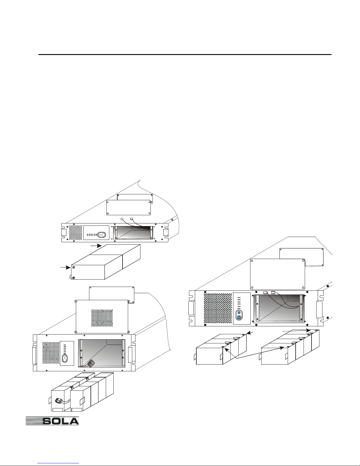
Use the drawings below to identify the location on the battey pack in the model SOLA520
Rackmount that you have.
4
Remove the screws holding the exterior battery access panel (1) to the front panel. Set the
screws and panel aside.
750
1
2
Red (+)
Black(-)
1
2
2250
1050 and
1425
1050
Batteries
1425
Batteries
Red (+)
2
1
Black (-)
Page 17
13
SOLA Never Stops Innovating
5
Remove the screws holding the interior panel (2) to the battery chamber. Use care to avoid
dropping screws inside the unit. Set the screws and panel aside.
6
Use the tabs attached to the batteries to remove the batteries from the SOLA 520
Rackmount. Do not pull batteries out by pulling on battery terminals or cables.
7
Disconnect the red and black cables from the used battery pack.
For 2250 model:Disconnect the battery plug from the cable jack in the unit.
Dispose of old batteries properly.
8
Reconnect the cables to the new battery pack; red to positive (+), black to negative (-).
For 2250 model:Plug the battery cable into the unit’s cable jack.
9
Position the battery cables so they will not be pinched by the interior panel or the battery
pack. Slide the battery pack into the unit.
10
Use the screws removed earlier to re-install the interior panel to the battery chamber and the
exterior panel to the front panel.
11
If you followed the option in step 2:Reconnect the line cord to the SOLA520 Rackmount
and turn the unit on.
12
Reconnect the load equipment. Switch on the protected load equipment one piece at a time.
Communication Port
The SOLA520 Rackmount is plug-and-play compatible with Windows 95.
The SOLA 520 Rackmount comes equipped with CheckUPS II power management software.
Instructions included with the CheckUPS IICD tell you how to install the software. An interface
cable for the following systems is provided.
SCO UNIX/XENIX UNIX and Compatible Systems OS/2
Windows 3.X, 95 and NT Novell NetWare
SOLA offers interface kits that allow you to connect many other computer systems to the SOLA
communication port. For the following computer systems, or specific information on SOLA
interface kits, call SOLA Service or your local SOLA dealer.
Banyan VINES IBM RS/6000 AIX IBM AS/400 special
Lantastic v4.0 LAN Manager/Server v2.0
Page 18
14
SOLA Never Stops Innovating
DB-9 Pinouts
Pin 1 RS232 Receive Data:Receives incoming RS232 communication data.
Pin 2 RS232 Transmit Data:Sends outgoing RS232 communication data.
Pin 3 Normally Open On-Battery Contact:A normally open contact that closes 15 seconds
(pulls to Common) after the UPS switches to battery power.
Pin 4 Common:The signal ground for all signal pins.
Pin 5 Normally Open Low-Battery-Alarm Contact:A normally open contact that closes
(pulls to Common) during a Low Battery Alarm. This tells CheckUPS II and other
shutdown software when to start a computer shutdown.
Pin 6 Plug and Play Sense for Windows 95.
Pin 7 Remote Shutdown:Connecting this pin to Common for at least 5 seconds, while the
UPS is operating on battery, shuts the UPS off after 120 seconds.
Pin 8 Normally Closed On-Battery Contact:A normally closed contact that opens
15 seconds (releases from Common) after the UPS switches to battery power.
Pin 9 Unused.
Contacts consist of open collector circuits capable of switching up to +30 VDC, 6 mA resistive
load.
Specifications
SOLAreserves the right to change specifications without prior notice.
Line Transient Protection:Passes ANSI/IEEE C62.41 Category A testing.
Safety Compliance:TÜV/GS listed, AS3260.
EMC Compliance:CISPR 22 Class B, Vfg 243-91/46-92 B, EN55022, CE Mark Self-certified to: CE
Marking Directive 93/68/EEC, Low Voltage Directive 73/23/EEC, C-tick, AS3548.
Noise (RF) Suppression:Full-time EMI/RFI filtering.
Efficiency:> 95% on line.
Capacity VA/Watts:750VA / 450W; 1050VA / 670W; 1425VA / 950W; 2250VA / 1600W.
Voltage Nominal: 240 VAC
Voltage Range: 0 to 300 VAC operating on battery and buck/boost; 197 to 283 VAC operating without bat-
tery discharge.
Frequency:50/60 Hz auto-sensing 55 - 65 Hz (60 Hz); 45 - 55 Hz (50 Hz) (50/60 Hz ± 0.5 Hz on battery.)
Typical Runtime (minutes):750 and 1050VA Models:Full load: 6 minutes. Half load: 19 minutes.
1425VA Models:Full load: 5 minutes. Half load: 17 minutes.
2250VA Models:Full load 5 minutes. Half load: 16 minutes.
Transfer Time:4 ms typical.
Page 19

15
SOLA Never Stops Innovating
Battery:Sealed, maintenance-free, valve-regulated, UL 924 recognized.
750 VA Models: Two 12 V, 7.0/7.2 AH batteries. Nominal Voltage is 24 VDC.
1050 VA Models: Three 12 V 7.0/7.2 AH batteries. Nominal Voltage is 36 VDC.
1425 VA Models: Four 12 V 7.0/7.2 AH batteries. Nominal Voltage is 48 VDC.
2250VA Models: Eight 6 V, 12.0 AH batteries. Nominal Voltage is 48 VDC.
Automatic Battery Test: Automatic battery test occurs upon startup and every 14 days thereafter. Alarm
will sound if the battery fails this test.
Battery Recharge Time (to 95% of capacity):750 VA, 1050 VA, 1425 VA, and 2250 VA:3 hours;
1425 VA: 7 hours with output fully loaded. Recharge time is
lower with reduced load.
Overcurrent Protection (on line):All Models:Circuit Breaker.
Input Fault Current (maximum): 750 and 1050 Models:15 A. 1425 Model: 26.1 A.
2250 Model: 35 A.
AC input Plug/Cord Information:
750 VA - CEE 22, recessed plug.
1050 VA - CEE 22, recessed plug.
1425 VA - CEE 22, recessed plug.
2250 VA - CEE 19, recessed plug.
AC Output Distribution:
750 VA - (3) Aust 10 A.
1050 VA - (4) Aust 10 A.
1425 VA - (4) Aust 10 A.
2250 VA - (4) Aust 10 A.
Load Compatibility:Can support 100% power factor corrected, switch-mode power supply load.
Audible Noise:< 45 dBa at one meter, except 2250 VA model which is < 55 dBa at one meter.
Ventilation:Air around the unit must be free of dust, chemicals, or other materials that corrode or
contaminate. Air must be free to move around the unit.
Operating Temperature:0° - 40° C.
Storage Temperature: -15° to +50° C. Battery life is reduced above 25 ° C.
If the SOLA520 Rackmount unit is stored, the batteries should be recharged
every 6 months.
If stored above 25°C, recharge the batteries more often.
Humidity:5% - 95% RH (non-condensing).
Dimensions (Height x Width x Length):750 VA: 448 x 475 x 88 mm
1050 & 1425VA: 448 x 475 x 133 mm
2250 VA: 448 x 475 x 178 mm
Weight:750: 18.0 kg 1425:26.0 kg
1050:23.3 kg 2250:39.1 kg
Page 20
16
SOLA Never Stops Innovating
Appendix A: Adjusting Voltage Settings
When the unit is not sounding an alarm,you can use the Alarm/Program button shown below to
change the following:
• Nominal Voltage — The normal voltage the SOLA520 Rackmount is programmed to expect, and
the nominal UPS output voltage under line loss conditions.
• Buck — The input voltage at which the SOLA 520 Rackmount decreases voltage before providing
output because the input voltage is too high.
• Boost — The input voltage at which the SOLA 520 Rackmount increases voltage before providing
output because the input voltage is too low.
• Transfer to Inverter — The point at which the SOLA 520 Rackmount switches to inverter (battery
power), either because AC input voltage is very low or because it is very
high.
Note: Make sure you want to change these values before
you start the procedure below. Once you press the
button shown for 10 seconds, the values will change
to the default values, and any previous changes you
have made will be lost. If you have questions, contact
the nearest SOLA office, or call National Service and
Repair Centre on: 1800 034 401 (except Melbourne);
9768 3105 (Melbourne only).
Do not change voltage settings when unit is operating on batteries. To change the values, follow these
steps:
1.Press the button shown until LEDs on the front of the SOLA520 Rackmount blink. After the
LEDs blink, three will stay lit and the SOLA 520 Rackmount will beep for one second.
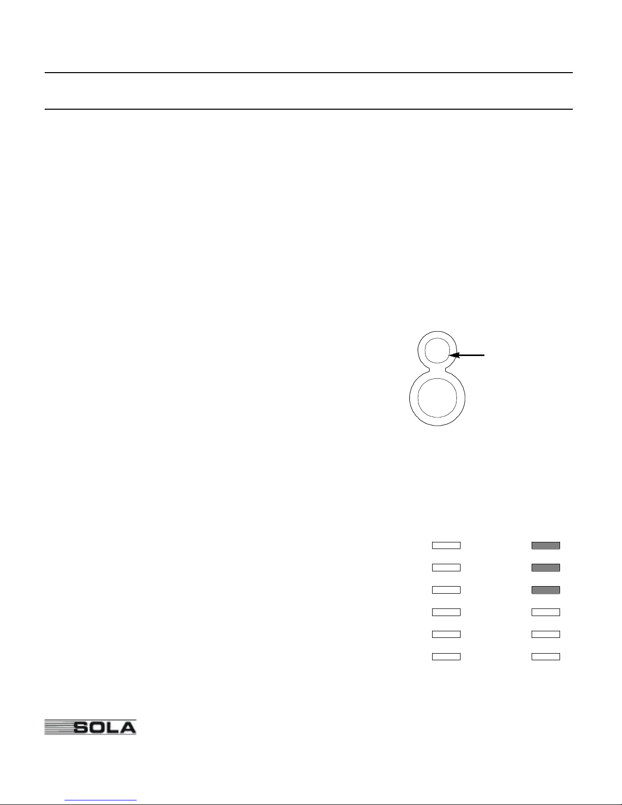
2.The LEDs that are lit show which voltage settings are
selected. The LEDs are numbered in the drawing below to
help you identify them. Table 4 on page 16 shows the voltage settings for each possible combination of LEDs.
For example, with the default setting, LEDs 1, 2, and 3 will
be lit (see diagram). This combination of LEDs is the first
row of Table 5. This row shows the following:
• With 197 volts input or lower, the SOLA 520
Rackmount switches to battery power.
Press this
button for 10
seconds (until
all of the lights
blink).
1
(D)
(C)
(B)
(A)
2
3
4
5
6
1
2
3
4
5
6
LED Numbers Default Setting
Page 21
17
SOLA Never Stops Innovating
• When input voltage drops to 221, the SOLA 520 Rackmount begins to increase (boost) the
output voltage.
• 240 is the nominal or expected input voltage.
• When input voltage rises to 254, the SOLA520 Rackmount begins to decrease (buck) the
output voltage.
• With 283 volts input or higher, the SOLA520 Rackmount switches to battery power.
3.
Use the table below to decide which combination of
settings you need; note which LEDs must be lit for this
combination.
Then, press (for about 1 second)and
release the button to move to the next combination of
LEDs. If you hold the button in longer than 10 sec-
onds, the SOLA 520 Rackmount will save the setting
that is displayed.Continue pressing and releasing the
button until the proper LEDs are lit.
4.Once the correct LEDs are lit, press and holdthe button
for 10 secondsto save your changes. If the SOLA 520
Rackmount is running on AC input power, the display
will change back to the percent of full load. The new values will take effect after the display returns to normal
mode.
Press this button
for 10 SECONDS
to save your
changes.
Press this button
BRIEFLY to
scroll through the
settings.
LEDs Lit
To Inverter
(Input AC is Low)
Boost
Nominal
Voltage
Buck
To Inverter
(Input AC is High)
1, 2, 3
(Default)
197 221 240 254 283
2, 3, 6 170 191 230 244 271
3, 4, 5 181 202 220 233 259
3, 4, 6 167 187 220 233 259
1, 2, 4 193 216 240 254 283
1, 2, 5 182 204 240 254 283
1, 2, 6 178 199 240 254 283
2, 3, 4 189 212 230 244 271
2, 3, 5 185 207 230 244 271
2, 3, 5, 6 175 196 230 244 271
Table 4: Voltage Settings (750, 1050, 1425, and 2250 VA)
Page 22
Page 23
Page 24

20
SOLA Never Stops Innovating
Warranty
WARRANTY Information
This Warranty is subject to SOLA’s standard Conditions of Sale which govern all sales of products
by SOLA Australia Ltd.
1.SOLAproducts, in general, are warranted against failure due to faulty materials and/or
workmanship for a period of two years from despatch date (ex SOLA store) as per invoice.
The Ferroresonant and 95 Series Power Conditioners and SOLA Dry Type Transformers
have an extended warranty - 5 years from date of despatch.
2.If, within the applicable Warranty period, any SOLA product does not meet the warranty
specified above, and the product was installed and operated in accordance with Australian
standards and SOLA standard installation procedures, SOLA shall thereupon correct any
defects due to faulty materials and/or workmanship.
3.Any modifications made to the product other than those made by SOLA or its authorised
representative may cause the Warranty to be void.
4.For units up to 3kVA that are installed as a portable device, the Warranty covers repair or
replacement of defective parts at the factory, or other service locations as nominated by
SOLA Australia, provided the unit has been returned by the user packed adequately to
prevent shipping damage, and approval has been obtained from SOLA Australia Ltd before
shipment. All costs associated with the return of the product to SOLA Australia are at the
customer’s expense.
5.Units returned for in-warranty repairs, which are found not to be defective, will be subject to
an inspection and handling charge, plus transportation charges.
6.High grade batteries, designated for Uninterruptible Power Supply (UPS) applications, are
supplied by SOLA for use with SOLAUPS equipment. These batteries have a finite life
expectancy depending on a number of variables, including rate of discharge, depth of discharge, operating temperature, etc.
7.Providing that the batteries are used within the limits as set out in the battery manufacturer’s
warranty statement and are provided as an integral part of new equipment, they are guaranteed for two years, from despatch date as per invoice. A copy of this warranty statement is
available on request. Batteries provided as spare parts or replacements have a one year warranty. Other optional warranty terms for batteries are available on request.
Page 25
21
SOLA Never Stops Innovating
8.SOLA reserves the right to charge for replacement batteries if within the one year guarantee
period replacement batteries are necessary as a result of misuse or misapplication by the purchaser or end user.
SOLA Australia Offices
Head Office - Melbourne
SOLA Australia Ltd.
13 Healey Road
Dandenong VIC 3175
Phone: 61-3-9706-5022
Fax: 61-3-9794-9150
National Service and Repair Centre Free Call: 1800 034 401 (except Melbourne)
9768 3105 (Melbourne only)
Customer Service Offices
Adelaide
POBox 481, Marlestone Business Centre
SA 5033
Phone: 08-8347-3622
Fax: 08-8445-6328
Brisbane
Unit 2, 8 Lockhart Street
Woolloongabba, QLD 4102
Phone: 07-3891-1211
Fax: 07-3891-2492
Perth
Unit 2, 321 Great Eastern Highway
Redcliffe WA 6104
Phone: 08-9478 3511
Fax: 08-9479-4577
Sydney
67A Ryedale Road
West Ryde NSW 2093
Phone: 02-9949-6000
Fax: 02-9907-9802
Page 26

22
SOLA Never Stops Innovating
You have purchased a UPS that will provide you with many years of service, protecting your equipment from surges,
sags, and blackouts. This product incorporates the highest quality standards in engineering, manufacturing and testing,
and carries a 2 year warranty against defects in material and workmanship. This product is backed by over 60 years of
pride and integrity. We are sure you will agree, there is no substitute for a SOLA.
SOLA is one of the Best group of companies.
Did you know that SOLA also makes:
• Single Phase UPS systems up to 15kVA
• Three Phase UPS systems to 120kVA
• Parallel Three Phase UPS Systems to 1MVA
• Plug in Power Conditioners to 3kVA
• Hardwired Single Phase Power Conditioners to 22.5kVA
• Constant Voltage Transformers to 7.5kVA
• AC/DC switching and linear Power Supplies
• CVDC Constant Voltage Ferroresonant Power Supplies
• Low Voltage General Purpose Transformers
• Industrial Control Transformers
SOLA products are available through an extensive distribution network. These distributors offer literature, technical
assistance, and a wide array of off-the-shelf products for the fastest possible delivery. In addition, SOLA field sales
offices are conveniently located to provide prompt attention to customer needs. Call SOLA/direct to find the location
of your closest authorised distributor.
SOLA/BEST Offices
SOLA Australia Ltd. Best Power Best Power Technology Limited
13 Healey Road PO Box 2 BEST House, Moorside Road
Dandenong VIC 3175 Necadah, Wisconsin 54646 Winchester, Hampshire
AUSTRALIA USA ENGLAND SO23 7RX
Phone: 61-3-9706 5022 Phone: 1-608-565 7200 Phone: 44-1962-844414
Fax: 61-3-9794 9150 Fax: 1-608-565 2221 Fax: 44-1962-841846
Best Power Technology GmbH Borri Elettronica Industriale Srl Best Power Technology AG
Am Weichselgarten 23 Via dei Lavoratori, 124 Limmatstrasse 12
D-91058 Erlangen 20092 Cinisello Balsamo (Mi) 8957 Spreitenbach
GERMANY MILAN ITALY SWITZERLAND
Phone: 49-9131-77700 Phone: 39-2-6600661-2 Phone: 41-56-4183030
Fax: 49-9131-777050 Fax: 39-2-6122481 Fax: 41-56-4183033
Best Power Technology Pte. Ltd. Best Power Technology Mexico, S.A de C.V
30 Prinsep Street #07-00 Golfo de Riga, 34, Colonia Tacuba, Mexico D.F. 11410
SINGAPORE 188647 MEXICO
Phone: 65-430 6128 Phone: 52-5-399 0369
Fax: 65-430 6170 Fax: 52-5-399 1320
SOLA/BEST: Worldwide Manufacturers of Power Protection, Conversion and Transformation Products
 Loading...