


Assembly Manual
Guide d’assemblage
Sunshelter 12 x 16 ft.
Exact dimension of the roof, corner-to-corner: 142.9 x 194.1 inch
Min. dimension required for the base: 137.8 x 189 inch
Sojag code: E500-5157871
UPC code: 772830157871
© Sojag inc. 2015
Abri-soleil 3,6 x 4,88 m
Dimension exacte du toit, coin à coin : 363 x 493 cm
Dimension min. requise pour la base : 350 x 480 cm
Code Sojag : E500-5157871
Code CUP : 772830157871

IMPORTANT
Read the owner’s manual and make sure all parts
are included PRIOR to the start of assembly.
IMPORTANT
Lire le guide de l’utilisateur AVANT
de débuter l’assemblage du produit.
2
© Sojag inc. 2015

HARDWARE KIT TROUSSE DE QUINCAILLERIE
NOTE:
Parts not shown to actual size and not to scale.
X3
U
X1
X30
NOTE :
Le matériel n’est pas représenté à l’échelle.
X112
V
X60
Y
X
X8
X1
Z
Item Description Qty
U Screw M6X20 3
V Screw M6X15 112
X Screw M6X10 (D10x20) 8
X1
Screw M6X10 with Cap Nut
30
Y Screw St4.8x12 60
Z Allen Key 1
X1
W2
Pièce Description Qté
U Vis M6X20 3
V Vis M6X15 112
X Vis M6X10 (D10x20) 8
X1
Vis M6X10 et écrou borgne
30
Y Vis St4.8x12 60
Z Clé hexagonale 1
W2 Wrench 1
W2 Clé plate 1
© Sojag inc. 2015
3

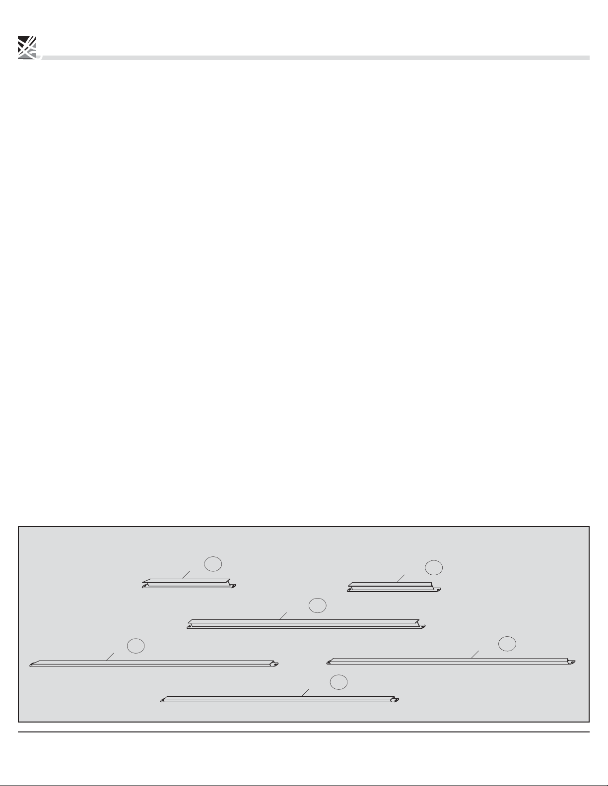
PARTS LIST LISTE DES PIÈCES
NOTE:
Parts not shown to actual size and not to scale.
B
B1
D
X2
X2
X6
NOTE :
Le matériel n’est pas représenté à l’échelle.
X4
A
X4
F
X2
C
X2
C1
G2
X2
G
X4
G1
F1
X4
A1
X4
X2
E
Item Description Qty
A Column 4
A1 Column 2
B Ogee 2
B1 Ogee 2
C Ogee 2
C1 Ogee 2
D Roof Bar 6
E Roof Bar 3
E1 Roof Bar 1
F Solidifying Bar 4
F1 Solidifying Bar 4
X3
X1
E1
Pièce Description Qté
A Colonne 4
A1 Colonne 2
B Moulure 2
B1 Moulure 2
C Moulure 2
C1 Moulure 2
D Barre de toit 6
E Barre de toit 3
E1 Barre de toit 1
F Barre de renfort 4
F1 Barre de renfort 4
G Roof Support Bar 4
G1 Roof Support Bar 4
G2 Roof Support Bar 2
4
G Barre de support de toit 4
G1 Barre de support de toit 4
G2 Barre de support de toit 2
© Sojag inc. 2015

H
X4
J1
X4
X4
H1
X4
I
X4
I1
X2
I2
X1
K
X4
J2
X4
L
L1
X2
M
H2
X10
X2
K1
X1
Item Description Qty
H Solidifying Bar 4
H1 Solidifying Bar 4
H2 Solidifying Bar 2
I Roof Finishing Bar 4
I1 Roof Finishing Bar 4
I2 Roof Finishing Bar 2
K Outside Roof Connector 1
K1 Inside Roof Connector 1
L
L1
Base
4
Base
2
J1 Corner Cover 4
J2 Joint Cover 4
M Finishing End 10
© Sojag inc. 2015
Pièce Description Qté
H Barre de renfort 4
H1 Barre de renfort 4
H2 Barre de renfort 2
I Barre de finition de toit 4
I1 Barre de finition de toit 4
I2 Barre de finition de toit 2
K
K1
Connecteur de toit extérieur
Connecteur de toit intérieur
1
1
L Base 4
L1
Base
2
J1 Cache-coin 4
J2 Cache-joint 4
M Embout de finition 10
5

PARTS LIST (CONTINUED) LISTE DE PIÈCES (SUITE)
NOTE:
Parts not shown to actual size and not to scale.
X4
N
X8
O
Ra
X4
N1
P
X4
X4
NOTE :
Le matériel n’est pas représenté à l’échelle.
N2
X48
Q
X2
T1
X2
T2
X2
Rb
Sb
X4
X4
Z1
X4
X4
Sa
Item Description Qty
N Solidifying Bar 4
N1 Solidifying Bar 4
N2 Solidifying Bar 2
O Iron Angle 8
P Union Bar 4
Q Hook 48
Ra Roof Panel 4
Rb Roof Panel 4
Sa Roof Panel 4
Sb Roof Panel 4
Pièce Description Qté
N Barre de renfort 4
N1 Barre de renfort 4
N2 Barre de renfort 2
O Fer angle 8
P Barre d’union 4
Q Crochet 48
Ra Panneau de toit 4
Rb Panneau de toit 4
Sa Panneau de toit 4
Sb Panneau de toit 4
T1 Roof Panel 2
T2 Roof Panel 2
Z1 Mosquito Net 4
6
T1 Panneau de toit 2
T2 Panneau de toit 2
Z1 Moustiquaire 4
© Sojag inc. 2015

ASSEMBLY ASSEMBLAGE
Step 1
1.1 Install the column (A/A1) on the base (L/L1)
using the screws (V).
Repeat for all remaining columns (A/A1).
A1
Étape 1
1.1 Installer une colonne (A/A1) sur une base (L/L1) en
utilisant les vis (V).
Répéter pour les colonnes (A/A1) restantes.
X4
A
L1
A1
V
V
X2
L1
Parts required for this step / Pièces requises pour cette étape :
A1
X2
A
X4
A
L
L
X2
L1
X4
L
V
X18
© Sojag inc. 2015
7

ASSEMBLY ASSEMBLAGE
Step 2
2.1 Insert 5 hooks (Q) into the first track of
each short ogee (B and B1).
2.2 Insert 5 hooks (Q) into the first track of
each long ogee (C and C1).
Repeat for all remaining ogees (B, B1, C and C1).
Étape 2
2.1 Insérer cinq crochets (Q) dans le premier rail de
chaque moulure courte (B et B1).
2.2 Insérer sept crochets (Q) dans le premier rail de
chaque moulure longue (C et C1).
Répéter pour les moulures restantes (B, B1, C et C1).
Parts required for this step / Pièces requises pour cette étape :
X2
B
X2
C
X2
C1
© Sojag inc. 2015
8
B1
X2
Q
X48
X4
Q
X5
B1
C1
B/B1
Q
X2
B
Q
X2
C
Q
Q
© Sojag inc. 2015
X4
Q
X7
C/C1
9

ASSEMBLY ASSEMBLAGE
Step 3
3.1 Insert the union bar (P) half way into the ogee (B1)
and attach with the screws (V) as illustrated.
3.2 Insert the other half of the union bar (P) into
the ogee (B) and insert the screws (V).
Ensure that the screws are tightened.
Repeat for all remaining ogees (B/B1).
Étape 3
3.1 Insérer la barre d’union (P) à mi chemin dans
la moulure (B1) et attacher avec quatre vis (V).
3.2 Insérer la seconde demie de la barre d’union (P)
dans la moulure (B) et y insérer quatre vis (V).
S’assurer que les vis sont bien serrées.
Répéter pour les moulures (B/B1) restantes.
Parts required for this step / Pièces requises pour cette étape :
X2
B
X2
P
© Sojag inc. 2015
10
V
X16
B1
X2

B1
X2
P
B
P
1
V
B1
X2
B
P
B1
B
1
B1
2
2
B
B1
© Sojag inc. 2015
V
X2
11

ASSEMBLY ASSEMBLAGE
Step 4
4.1 Insert the union bar (P) half way into the ogee (C1)
and attach with the screws (V) as illustrated.
4.2 Insert the other half of the union bar (P) into
the ogee (C) and insert the screws (V).
Ensure that the screws are tightened.
Repeat for all remaining ogees (C/C1).
Étape 4
4.1 Insérer la barre d’union (P) à mi chemin dans
la moulure (C1) et attacher avec quatre vis (V).
4.2 Insérer la seconde demie de la barre d’union (P)
dans la moulure (C) et y insérer quatre vis (V).
S’assurer que les vis sont bien serrées.
Répéter pour les moulures (C/C1) restantes.
Parts required for this step / Pièces requises pour cette étape :
X2
C
X2
C1
© Sojag inc. 2015
12
P
V
X2
X16

C1
X2
P
C
P
C1
V
1
X2
C1
C1
C
P
1
C
2
C
C1
2
© Sojag inc. 2015
X2
V
13

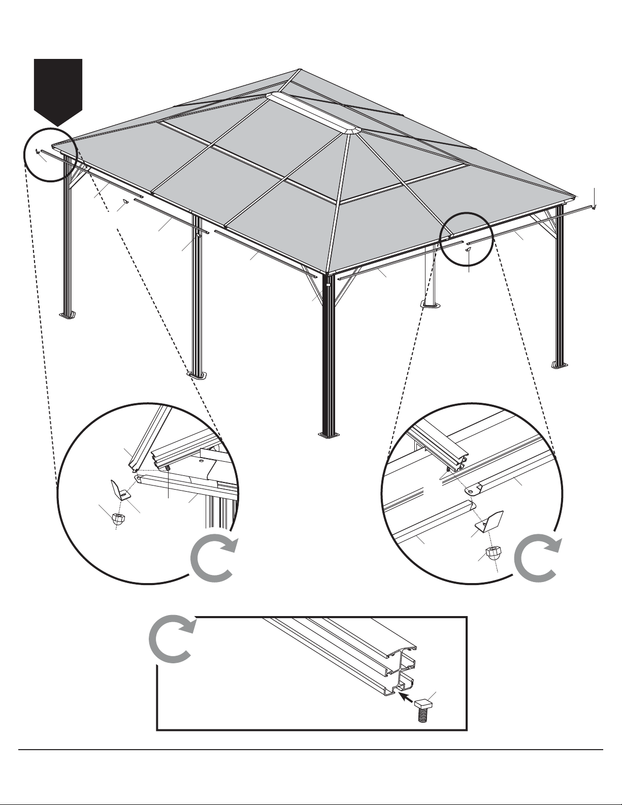
ASSEMBLY ASSEMBLAGE
CAUTION:
Always install the shelter on a level platform, wood or concrete.
Three people are required for this step.
Step 5
5.1 Install the short ogees (B and B1) between two
columns (A) using the screws (X) on the outside
of the ogees and the screws (V) on the inside
of the ogees.
5.2 Attach the long ogees (C and C1) to the
columns (A and A1) as illustrated using
the screws (V) and the iron angles (O) on
the inside of the ogees.
AVERTISSEMENT :
Toujours installer la structure sur une surface de niveau. Trois
personnes sont requises pour cette étape.
Étape 5
5.1 Installer les moulures courtes (B et B1) entre deux
colonnes (A) en utilisant les vis (X) à l’avant des
moulures ainsi que les vis (V) à l’arrière des moulures.
5.2 Attacher les moulures longues (C et C1) aux colonnes
(A et A1) tel qu’illustré en utilisant les vis (V) et les fer
angles (O) à l’intérieur des moulures.
Parts required for this step / Pièces requises pour cette étape :
O
X8
© Sojag inc. 2015
V
X32
14
X
X8

V
1
U
O
O
C1
3
B
V
A1
3
A1
B1
X2
C
V
1
2
A
A
X4
B
B1
2
1
3
C
A
C1
A1
1
2
A
1
2
A
© Sojag inc. 2015
2
X4
X
X
A
15

ASSEMBLY ASSEMBLAGE
Step 6
6.1 Install the joint cover plate (J2) using the screws
(Y) on the joint between the short ogees
(B and B1) and the long ogees (C and C1).
6.2 Install the corner cover (J1) using the screws (Y)
on each corner of the structure.
J2
2
J1
1
B1
2
B
J1
Étape 6
6.1 Attacher un cache-joint (J2) en utilisant les vis (Y) sur
tous les joints unissant les moulures courtes (B et B1) et
sur tous les joints unissant les moulures longues (C et C1).
6.2 Attacher un cache-coin (J1) en utilisant les vis (Y) sur
chacun des coins de la structure.
1
C1
J2
2
C
1
J1
C
J2
1
C1
2
Y
J1
X4
J2
X4
Parts required for this step / Pièces requises pour cette étape :
Y
J1
X4
J2
X4
B
Y
2
X28
Y
B1
J2
Y
J1
1
16
© Sojag inc. 2015

ASSEMBLY ASSEMBLAGE
Step 7
7.1 Fix the solidifying bars (F and F1) into each corner
of the structure using the screws (Y).
1
F1
F
F
Étape 7
7.1 Attacher les barres de renfort (F et F1) à l’intérieur de
chaque coin de la structure en utilisant les vis (Y).
1
F1
1
F
1
F1
F
F1
X4
Parts required for this step / Pièces requises pour cette étape :
Y
Y
X32
1
F
X4
F
F1
F1
X4
© Sojag inc. 2015
17

ASSEMBLY ASSEMBLAGE
Step 8
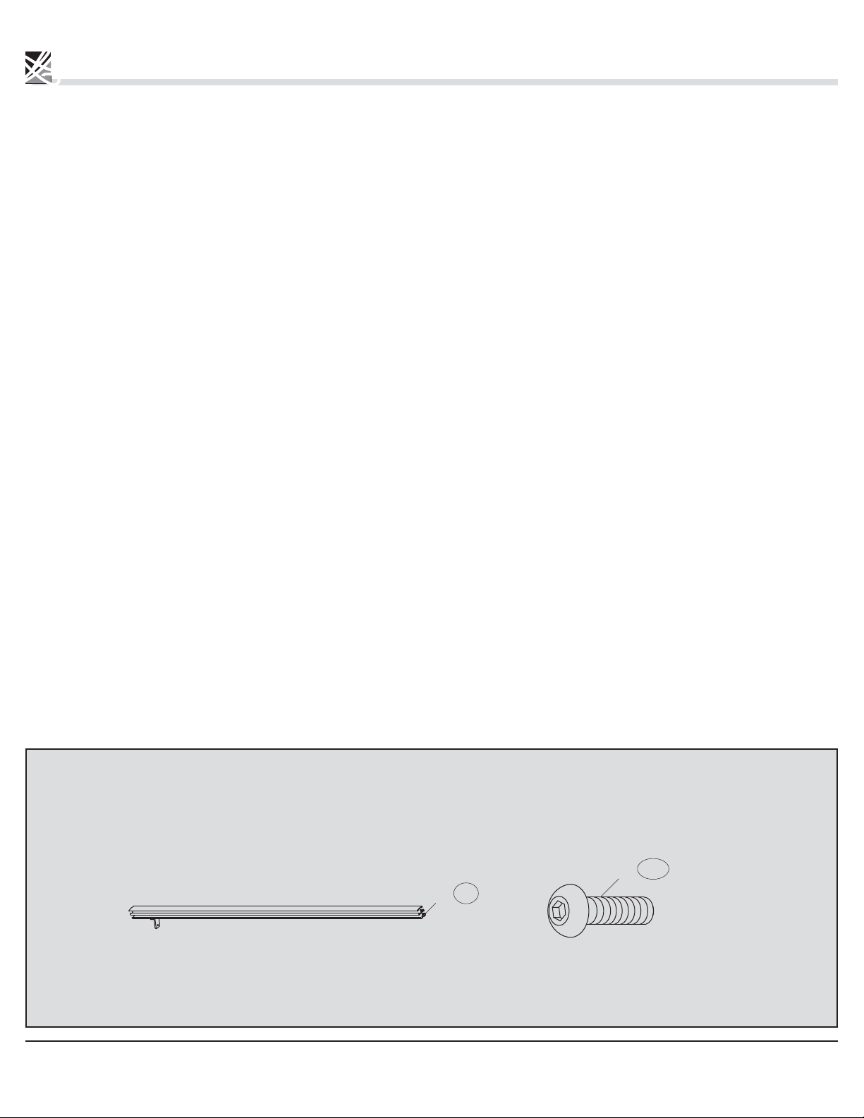
8.1 Slide two screws (X1) into the rail of each
roof bar (E & E1) as illustrated.
8.2 Slide two screws (X1) into each of the roof bars (D).
E/E1
X4
Étape 8
8.1 Glisser deux vis (X1) dans le rail de chaque barre de toit
(E et E1) tel qu’illustré.
8.2 Glisser deux vis (X1) dans le rail de chaque
barres de toit (D).
X2
X1
1
E/E1/D
X10
D
X1
X1
X6
X1
X1
Parts required for this step / Pièces requises pour cette étape :
X6
D
X3
E
X1
E1
1
1
X20
X1
18
© Sojag inc. 2015
ASSEMBLY ASSEMBLAGE
Step 9
9.1 Install the corner roof bars (E and E1) to the
inside roof connector (K1) using the screws (V)
as illustrated.
E
K1
E
Étape 9
9.1 Installer les barres de toit de coin (E et E1) au connecteur
de toit intérieur (K1) en utilisant les vis (V) tel qu’illustré.
K1
E
V
E1
X4
E1
E
E
Parts required for this step / Pièces requises pour cette étape :
X8
V
E
K1
K1
E
E1
X1
© Sojag inc. 2015
19
ASSEMBLY ASSEMBLAGE
Step 10
10.1 Place the roof structure on top of the ogees.
10.2 Screw the corner roof bars (E and E1) to the
columns (A) using the screws (V).
Étape 10
10.1 Placer la structure du toit sur le dessus des moulures.
10.2 Visser les barres de coin de toit (E et E1) aux
colonnes (A) en utilisant les vis (V).
Parts required for this step / Pièces requises pour cette étape :
X4
V
© Sojag inc. 2015
20
E
1
X4
1
E
E
&
E
1
E1
1
E1
V
1
© Sojag inc. 2015
21
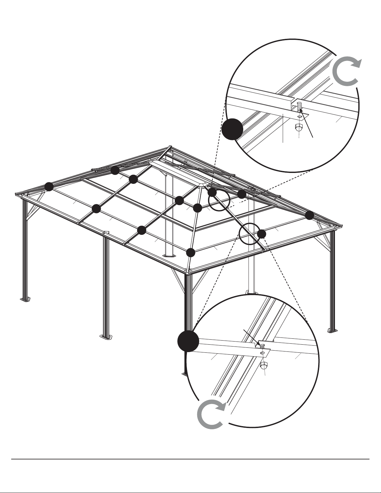
ASSEMBLY ASSEMBLAGE
Step 11
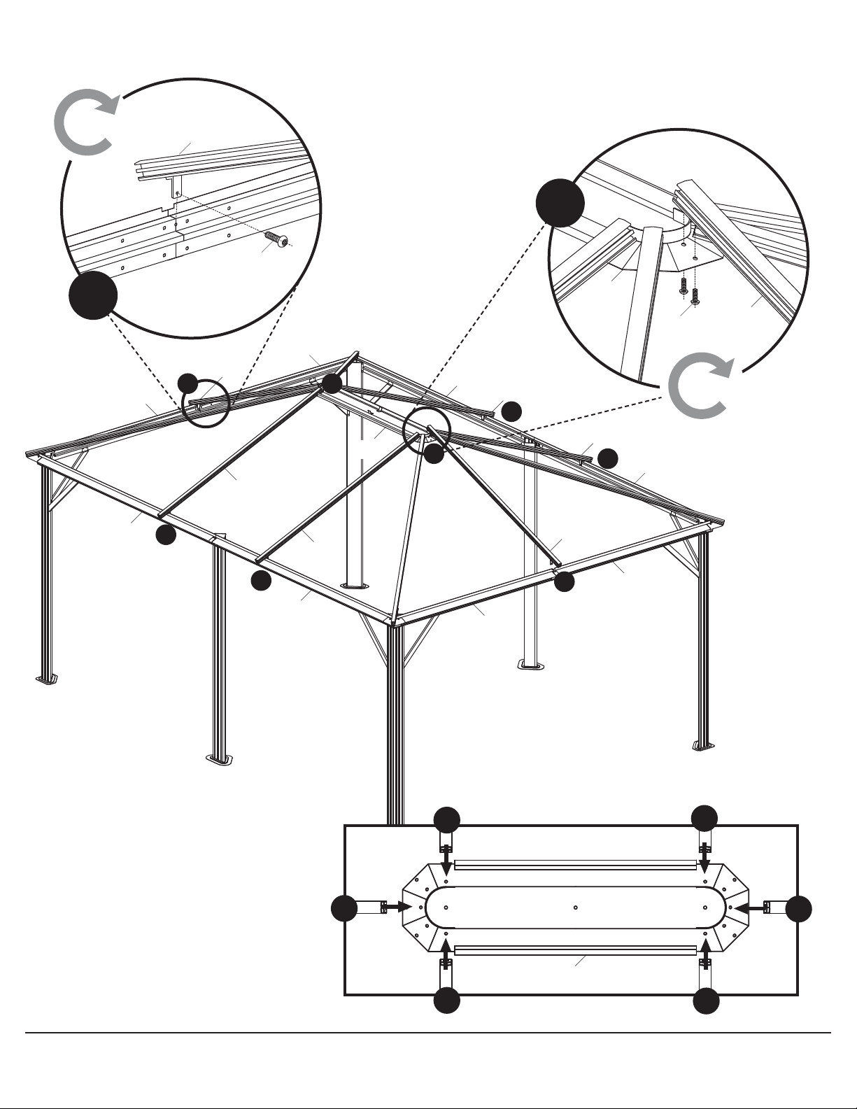
11.1 Install the middle roof bar (D) to the inside
roof connector (K1) using the screws (V).
11.2 Screw the iron angle on the middle roof bar (D)
to the ogees (B, B1, C and C1) using a screw (V).
Repeat for all remaining middle roof bars (D).
Étape 11
11.1 Installer les barres de toit du centre (D) au connecteur
de toit intérieur (K1) en utilisant les vis (V).
11.2 Visser le fer angle sur la barre de toit du centre (D)
aux moulures (B, B1, C et C1) en utilisant une vis (V).
Répéter pour toutes les barres de toit du
centre (D) restantes.
Parts required for this step / Pièces requises pour cette étape :
X6
D
© Sojag inc. 2015
22
V
X18
X6
D
2
V
1
C
B1
K1
V
B
D
1
D
1
1
C1
2
K1
D
C1
D
1
D
2
1
B
1
D
B1
X6
C
D
D
D
D
© Sojag inc. 2015
D
D
K1
D
23
ASSEMBLY ASSEMBLAGE
Step 12
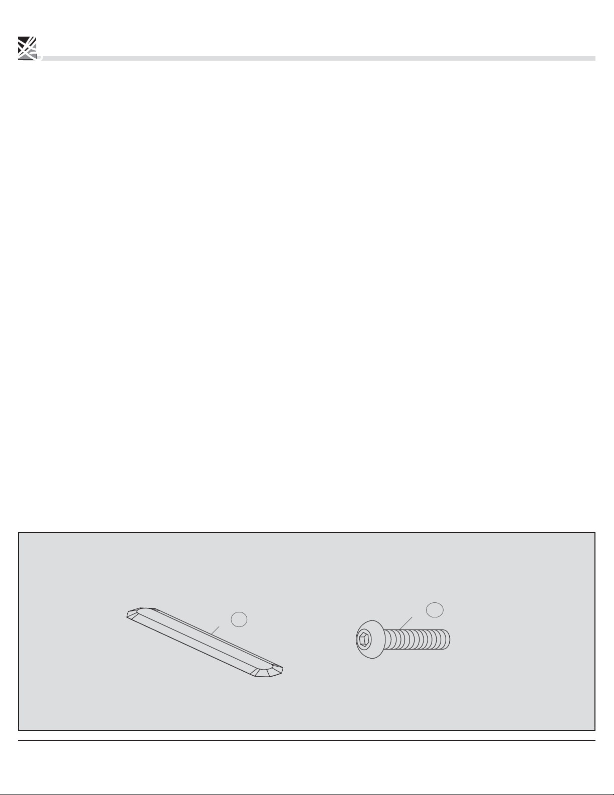
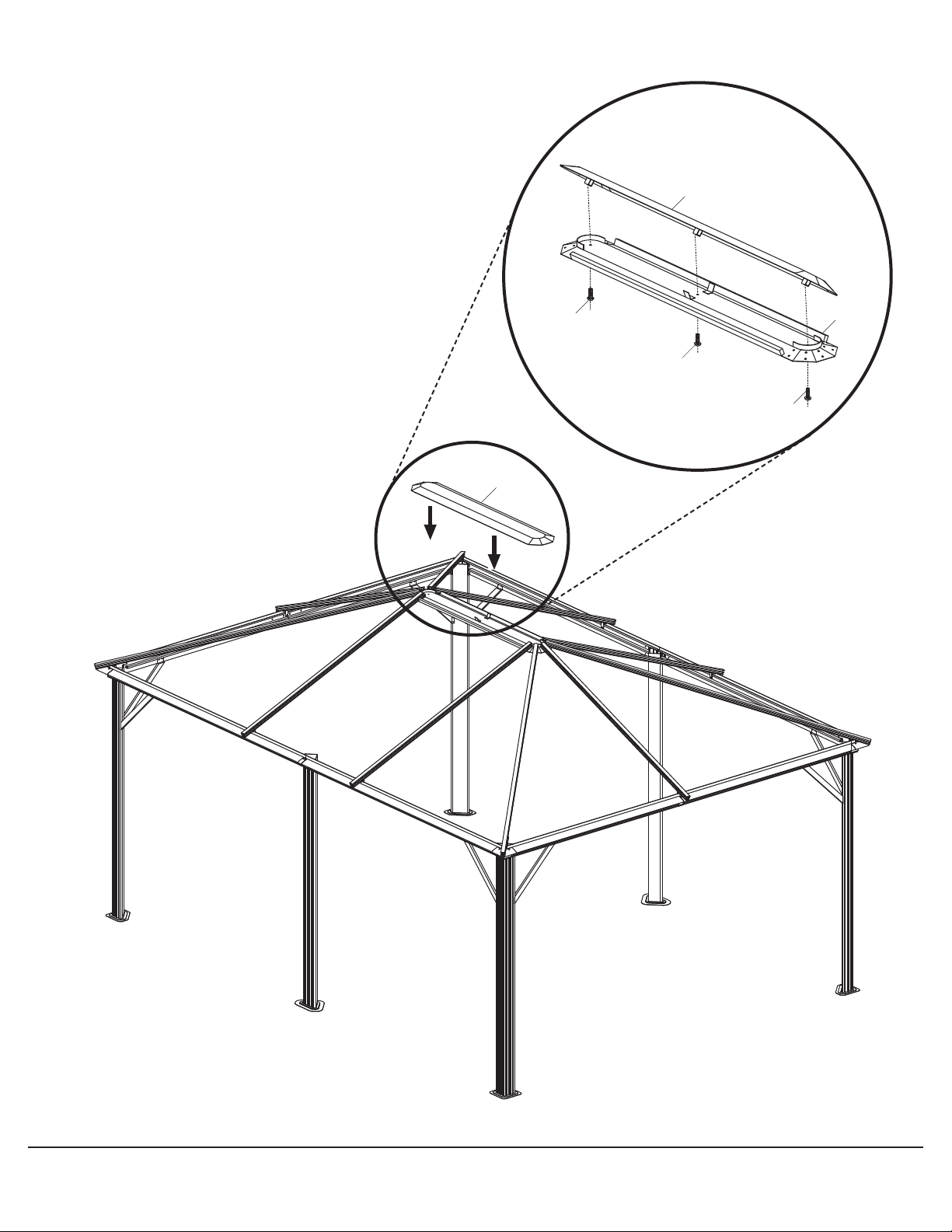
12.1 Install the outside roof connector (K) on the
inside roof connector (K1) using the screws (U).
Étape 12
12.1 Installer le connecteur de toit extérieur (K) sur le
connecteur de toit intérieur (K1) en utilisant les vis (U).
Parts required for this step / Pièces requises pour cette étape :
X1
K
© Sojag inc. 2015
24
U
X3
K
K
U
K1
U
U
© Sojag inc. 2015
25

ASSEMBLY ASSEMBLAGE
NOTE:
The roof panels are covered with a plastic film identifying which
side has a UV protector. Once the plastic film is removed it
is impossible to know which side has the UV protector. We
recommend removing the film one at a time just prior to
installing the roof panel.
CAUTION:
One side of the roof panels is UV protected. Ensure that the UV
protected side is facing up. It is a very important procedure;
if not followed as described, your roof will not be covered by
the warranty.
Step 13
13.1 Install the roof panels (Ra, T1 and Rb) according
to the picture, by sliding into the upper track of
roof bars (D, E and E1).
13.2 Align the base of middle roof panel (T1) with
bases of the left roof panel (Ra) and the right
roof panel (Rb). This may require that middle
roof panel (T1) not be completely pushed to
the back of the tracks.
Repeat this step all around the structure.
NOTE :
Les panneaux de toit sont recouverts d’une pellicule de plastique
identifiant le côté ayant une protection UV. Une fois que cette
pellicule est enlevée, il est impossible d’identifier quel côté est
protégé contre les rayons UV du soleil. Il est recommandé de
retirer les pellicules de plastique une à la fois, avant l’installation
de chacun des panneaux.
MISE EN GARDE :
Un des côtés du panneau de toit a une protection UV. S’assurer
d’exposer le côté protégé contre les rayons UV du soleil vers
l’extérieur de l’abri. Cette étape est très importante, si elle n’est
pas respectée telle que décrite, le toit ne sera pas couvert par
la garantie.
Étape 13
13.1 Installer les panneaux de toit (Ra, T1 et Rb) dans le rail
du haut se trouvant sur les barres de toit (D, E et E1).
13.2 Enligner la base du panneau de toit du centre (T1) avec
la base du panneau de toit de gauche (Ra) et la base
du panneau de toit de droite (Rb). Cela peut demander
que les panneaux de toit du centre (T1) ne soient pas
poussés complètement au fond des rails.
Répéter cette étape sur tous les côtés de l’abri.
Parts required for this step / Pièces requises pour cette étape :
X2
T1
X4
Ra
© Sojag inc. 2015
26
Rb
X4

E
E
D
T1
Ra
D
Rb
E1
Ra
Rb
E
D
This Side Up
Ce côté vers le haut
Ra/T1/Rb
© Sojag inc. 2015
27

ASSEMBLY ASSEMBLAGE
Step 14
14.1 Insert the roof support bar (G, G1 and G2)
according to the picture, by sliding into the
lower track of roof bars (D, E and E1)
as illustrated.
Repeat this step all around the structure.
Étape 14
14.1 Insérer la barre de support de toit (G, G1 et G2)
dans le rail du bas se trouvant sur les barres de toit
(D, E et E1) tel qu’illustré.
Répéter cette étape sur tous les côtés de l’abri.
Parts required for this step / Pièces requises pour cette étape :
X4
G
G2
© Sojag inc. 2015
28
X2
G1
X4

E
D
G
G2
E
E
G1
G/G1/G2
D
G1
E1
G
D
© Sojag inc. 2015
29

ASSEMBLY ASSEMBLAGE
NOTE:
The roof panels are covered with a plastic film identifying which
side has a UV protector. Once the plastic film is removed it
is impossible to know which side has the UV protector. We
recommend removing the film one at a time just prior to
installing the roof panel.
CAUTION:
One side of the roof panels is UV protected. Ensure that the UV
protected side is facing up. It is a very important procedure;
if not followed as described, your roof will not be covered by
the warranty.
Step 15
15.1 Install the roof panels (Sa, T2 and Sb)
according to the picture, by sliding them into
the lower track of roof bars (D, E and E1).
NOTE :
Les panneaux de toit sont recouverts d’une pellicule de plastique
identifiant le côté ayant une protection UV. Une fois que cette
pellicule est enlevée, il est impossible d’identifier quel côté est
protégé contre les rayons UV du soleil. Il est recommandé de
retirer les pellicules de plastique une à la fois, avant l’installation
de chacun des panneaux.
MISE EN GARDE :
Un des côtés du panneau de toit a une protection UV. S’assurer
d’exposer le côté protégé contre les rayons UV du soleil vers
l’extérieur de l’abri. Cette étape est très importante, si elle n’est
pas respectée telle que décrite, le toit ne sera pas couvert par
la garantie.
Étape 15
15.1 Installer les panneaux de toit (Sa, T2 et Sb) tel
qu’illustré en les glissant dans le rail du bas des
barres de toit (D, E et E1).
Parts required for this step / Pièces requises pour cette étape :
X2
T2
X4
Sa
© Sojag inc. 2015
30
Sb
X4

Sa
T2
Sb
Sb
Sa
Sa/T2/Sb
© Sojag inc. 2015
31

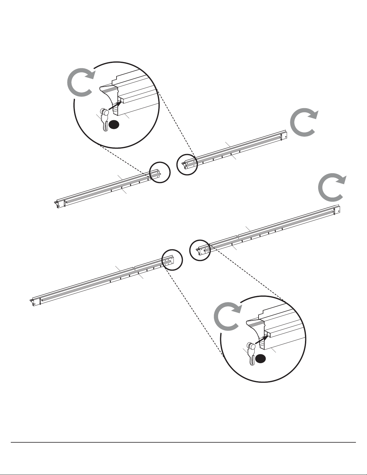
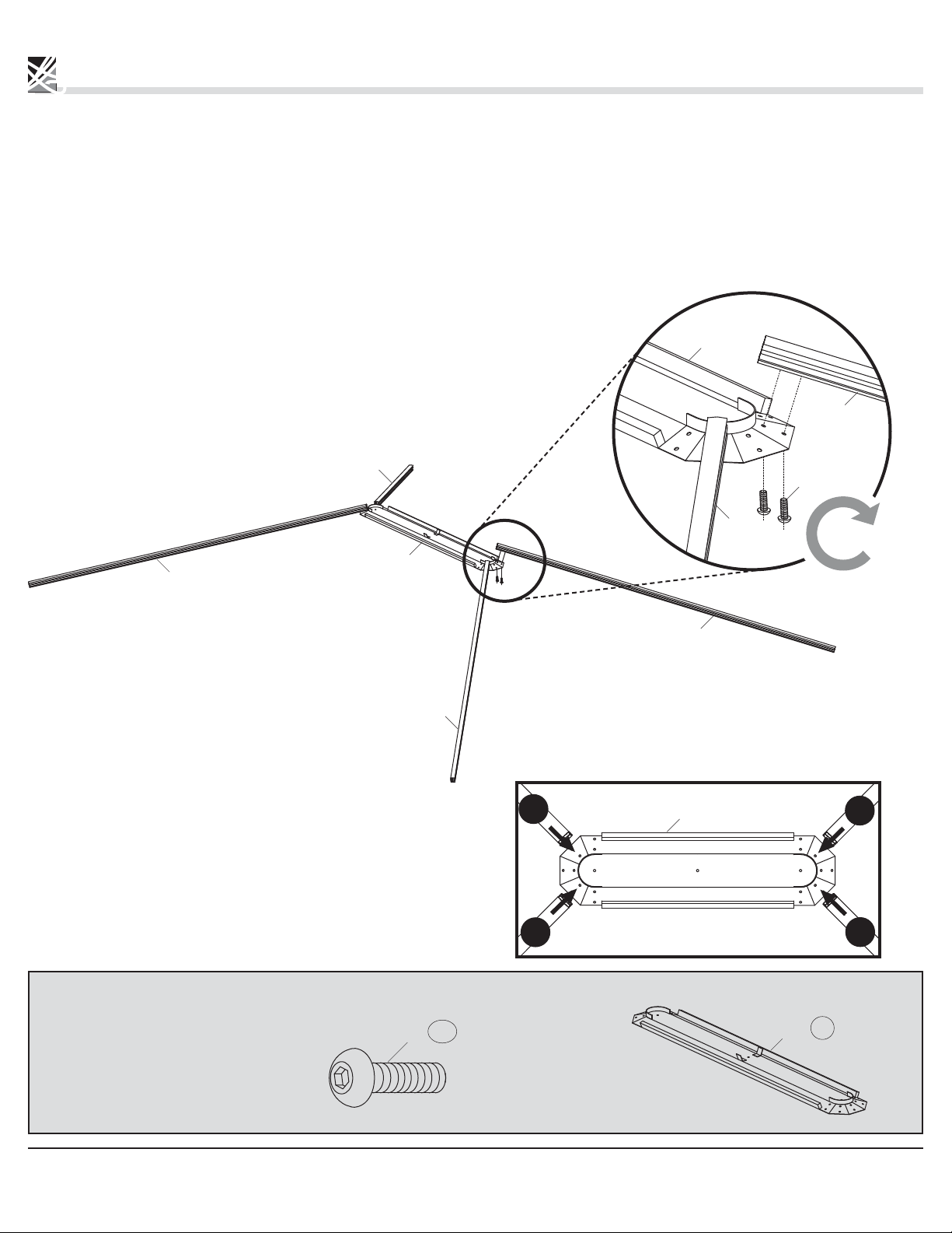
ASSEMBLY ASSEMBLAGE
CAUTION:
Two people are required for this step.
Step 16
16.1 Secure the left side of a left roof finishing bar (I)
with a screw and cap nut (X1) in the left corner
of the 4.88 m (16 ft.) side of the unit. This cap
nut (X1) will
end of this step.
16.2 Place a middle roof finishing bar (I2) next to
the left roof finishing bar (I) and align the
pre-drilled holes in each bar one on top of the
other. Place finishing end (M) over the aligned
holes and secure with screw and cap nut (X1).
16.3 Repeat this step with the right roof finishing
bar (I1) by securing it to the middle roof finishing
bar (I2) with a finishing end (M) and a screw and
cap nut (X1).
16.4 In order to transition from the 4.88 m (16 ft.) side
of the unit to the 3.66 m (12 ft.) side, align the
remaining pre-drilled hole of the right roof
finishing bar (I1) with that of a left roof finishing
bar (I) on the 3.66 m (12 ft.) in the corner of the
unit. Secure both bars in the corner with a
finishing end (M) by inserting a screw
and cap nut (X1).
16.5 Secure a right roof finishing bar (I1) to the left
roof finishing bar (I) on the 3.66 m (12 ft.) side
with a finishing end (M) and a screw and
cap nut (X1).
16.6 Repeat these steps working your way around the
entire unit until coming to the last corner where
the installation of the roof finishing bar began.
be undone and re-inserted at the
AVERTISSEMENT :
Deux personnes sont requises pour cette étape.
Étape 16
16.1 Attacher le côté gauche de la barre de finition de toit (I)
avec une vis et écrou borgne (X1) dans le coin gauche
du côté de 4,88 m (16 pi) de l’abri. Cet écrou borgne (X1)
sera défait et inséré de nouveau à la fin de cette étape
dans le but d’accrocher un embout de finition (M).
16.2 Placer une barre de finition de toit de centre (I2) à
droite de la barre de finition de toit gauche (I) et
aligner les trous les uns par-dessus les autres.
Placer un embout de finition (M) par-dessus les
trous et les attacher avec une vis et écrou borgne (X1).
16.3 Répéter cette étape avec une barre de finition de
toit droite (I1) en l’attachant sur la barre de finition
de toit du centre (I2) avec un embout de finition (M)
et une vis et écrou borgne (X1).
16.4 Dans le but de faire la transition du côté de 4,88 m (16 pi)
au côté de 3,66 m (12 pi), aligner le trou restant de la
barre de finition de toit droite (I1) avec celui de la barre
de finition de toit gauche (I) sur le côté de 3,66 m (12 pi)
au coin de l’abri. Attacher les deux barres au coin
avec un embout de finition (M) en y insérant
une vis et écrou borgne (X1).
16.5 Attacher une barre de finition de toit droite (I1) à la
barre de finition de toit gauche (I) sur le côté de
3,66 m (12 pi) avec un embout de finition (M)
et une vis et écrou borgne (X1).
16.6 Répéter ces étapes jusqu’à ce que vous ayez fait le
tour de l’abri et que vous arriviez au dernier coin
où vous avez commencé l’installation de la première
barre de finition de toit.
16.7
Undo the first cap nut (X1) and align the pre-drilled
holes of the first and last roof finishing bar which
were installed. Secure both bars in the corner
with a finishing end (M) by using the cap nut (X1).
16.7 Défaire l’écrou borgne (X1) et aligner les trous de la
première et de la dernière barre de finition de toit qui
ont été installées. Attacher les deux barres au coin avec
un embout de finition (M) en y insérant l’écrou
borgne (X1) que vous avez défait.
Parts required for this step / Pièces requises pour cette étape :
X4
I
X4
I1
© Sojag inc. 2015
32
X1
X10
I2
X2
M
X10
START
HERE
DÉBUTER
ICI
M
M
I
M
X1
I1
M
I2
M
X1
I1
I1
I
M
M
X1
I1/I2
I
X4 X6
X10
Slide the screw (X1) into the rail.
Glisser la vis (X1) dans le rail.
© Sojag inc. 2015
M
I/I2
X1
X1
33
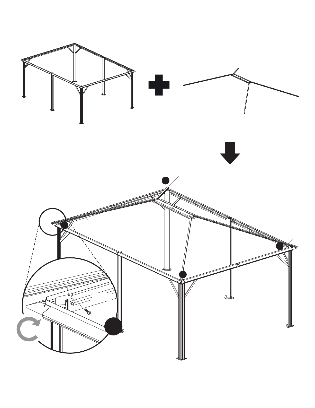
ASSEMBLY ASSEMBLAGE
Step 17
17.1 From the inside of the shelter, attach the
solidifying bars (N, N1, N2, H, H1 and H2) using
the pre-inserted screws and cap nut (X1) as
illustrated. Each screw (X1) must be inserted in
two ends of a solidifying bar prior to screw.
Étape 17
17.1 De l’intérieur de l’abri, installer les barres de
renfort (N, N1, N2, H, H1 et H2) en utilisant les
vis préinsérées (X1) et ses écrous borgnes tel
qu’illustré. S’assurer que chaque vis est insérée
dans les extrémités de deux barres de renfort
adjacentes avant de visser.
Parts required for this step / Pièces requises pour cette étape :
X4
N
X2
N2
X4
H
X2
H2
© Sojag inc. 2015
34
N1
X4
H1
X4
View from underside
of shelter
Vue lorsque vous êtes
positionné à l’intérieur
de l’abri
X10
2
N/N1/N2
Pre-inserted screw (X1)
N/N1/N2
2
2
1
H
1
N
N2
2
N1
2
2
2
N1
N
H2
1
1
H1
H1
1
H
Vis (X1) pré-insérée
1
Pre-inserted screw (X1)
Vis (X1) pré-insérée
1
H/H1/H2
X10
© Sojag inc. 2015
H/H1/H2
View from underside
of shelter
Vue lorsque vous êtes
positionné à l’intérieur
de l’abri
35
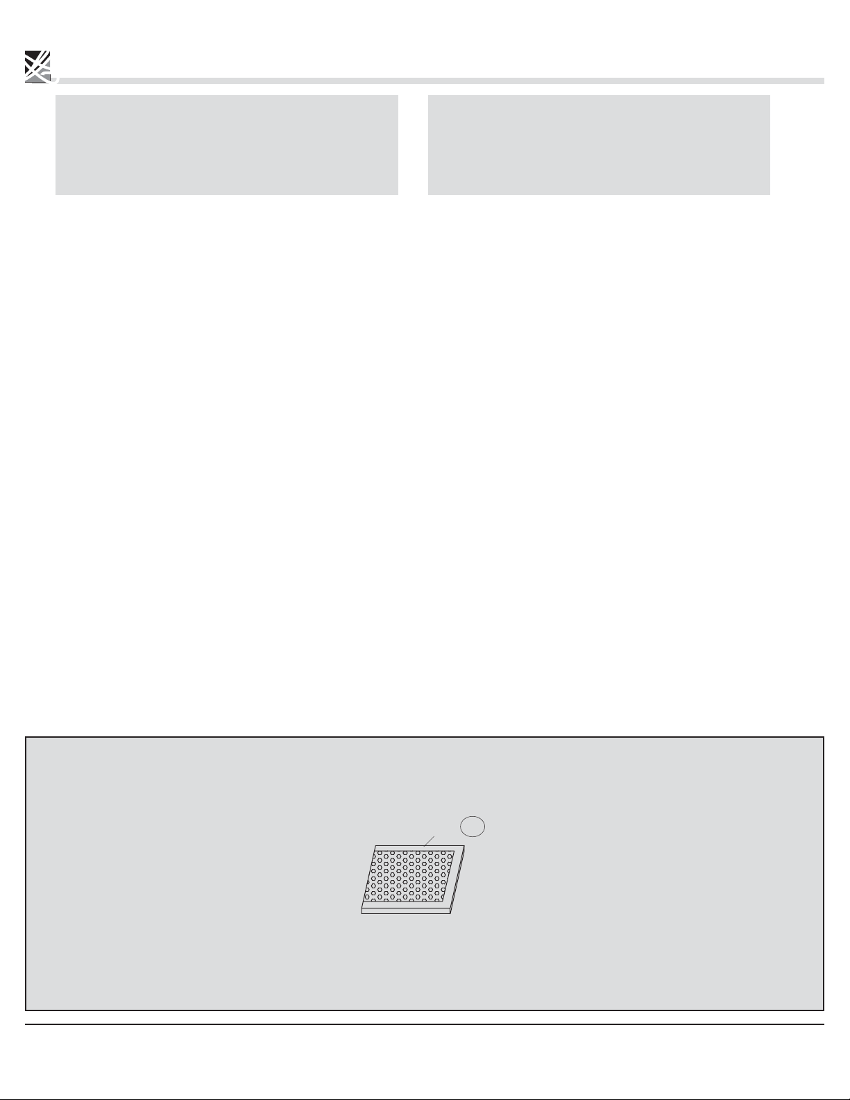
ASSEMBLY ASSEMBLAGE
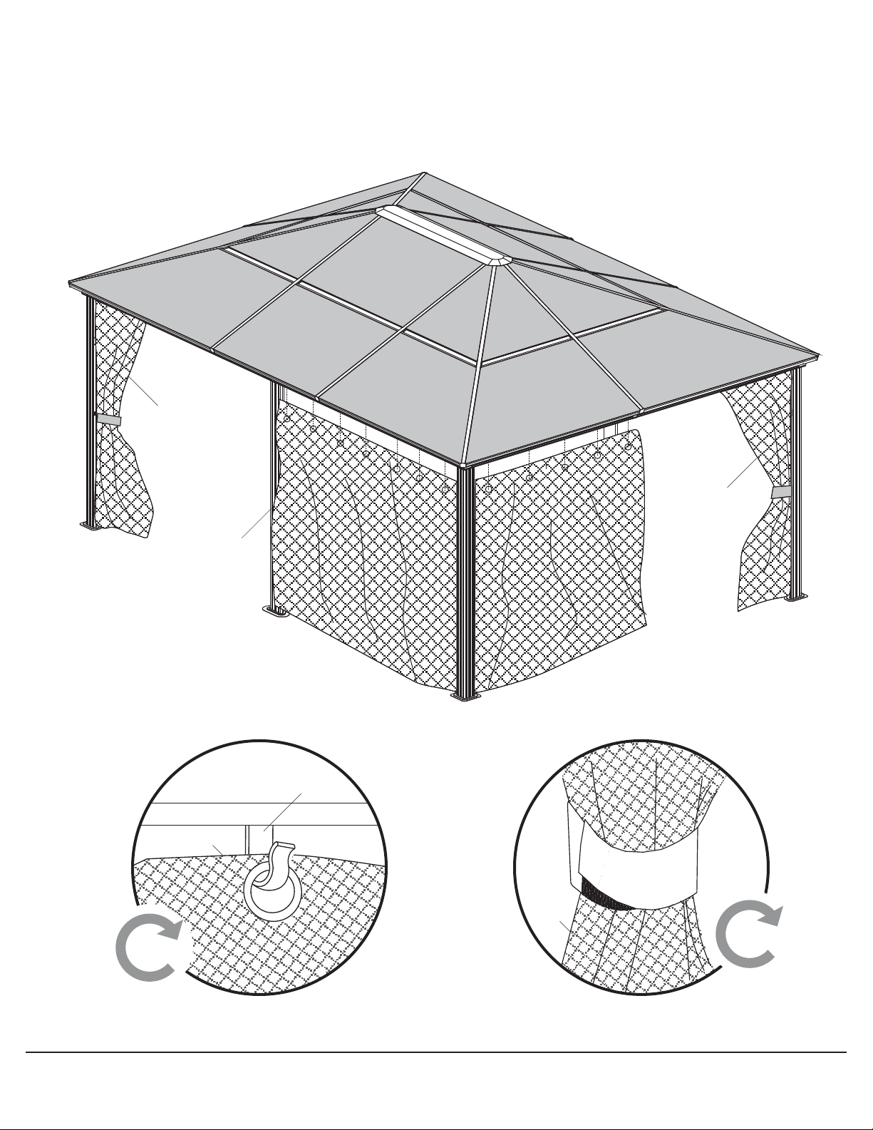
NOTE:
The netting should be installed starting in the middle of the 3.6
m (12 ft.) side of the unit, wrap around the inside of the post, and
finish the installation in the next side of the unit. The zippers to
close the netting will therefore meet in the centre of two columns
of the sun shelter.
Step 18
18.1 Install the mosquito netting (Z1) along the tracks
by inserting the hooks (Q) one at a time into the
eyelets found along the top border of the netting.
Repeat for all netting panels (Z1).
NOTE :
Les moustiquaires doivent être installées à l’intérieur de l’abri,
en commençant par le milieu d’un côté de 3,6 m (12 pi) de l’abri
et en se terminant au milieu du côté adjacent. Les fermetures
à glissière vont alors se rencontrer au centre de deux colonnes
de l’abri.
Étape 18
18.1 Installer les moustiquaires (Z1) sur les rails en
insérant les crochets (Q), les uns après les autres,
dans chacun des oeillets.
Répéter cette étape pour tous les moustiquaires (Z1).
Parts required for this step / Pièces requises pour cette étape :
X4
Z1
© Sojag inc. 2015
36
Z1
Z1
Z1
Q
X48
Z1
Z1
X4
© Sojag inc. 2015
37

Notes
38

Notes
39

www.sojag.ca
Printed in China / Imprimé en Chine
 Loading...