

Page 1

User Guide
PBpro ETH
Remote PROFIBUS Interface
Version: MMA-NN-012310 E-072014-02
© Copyright 2014 Softing Industrial Automation GmbH
Page 2

Disclaimer of liability
The information contained in these instructions corresponds to the technical status at the time of printing of it and is
passed on with the best of our knowledge. The information in these instructions is in no event a basis for warranty
claims or contractual agreements concerning the described products, and may especially not be deemed as warranty
concerning the quality and durability pursuant to Sec. 443 German Civil Code. We reserve the right to make any
alterations or improvements to these instructions without prior notice. The actual design of products may deviate from
the information contained in the instructions if technical alterations and product improvements so require.
It may not, in part or in its entirety, be reproduced, copied, or transferred into electronic media.
Softing Industrial Automation GmbH
Richard-Reitzner-Allee 6
85540 Haar / Germany
Tel: + 49 89 4 56 56-0
Fax: + 49 89 4 56 56-488
Internet: http://industrial.softing.com
Email: info.automation@softing.com
Support: support.automation@softing.com
The latest version of this manual is available in the Softing download area at: http://industrial.softing.com.
Page 3

Table of Contents
Table of Contents
Chapter 1
Chapter 2
Introduction
Purpose 1.3.1
..................................................................................................................... 5
Target group 1.3.2
..................................................................................................................... 5
Conventions used 1.3.3
..................................................................................................................... 6
Document history 1.3.4
..................................................................................................................... 6
Installation
..................................................................................5
................................................................................................ 51.1 About PBpro ETH
................................................................................................ 51.2 Safety precautions
................................................................................................ 51.3 About this document
................................................................................................ 71.4 Scope of delivery
................................................................................................ 71.5 Intended Use
..................................................................................8
................................................................................................ 82.1 Mounting
................................................................................................ 82.2 Electric connection
................................................................................................ 92.3 Power supply
................................................................................................ 92.4 PROFIBUS interfaces
................................................................................................ 102.5 Ethernet port
Chapter 3
3.3.4.1
3.3.4.2
3.3.4.3
................................................................................................ 102.6 Light Emitting Diodes (LED)
PBpro ETH Administration
System Status Information 3.2.1
..................................................................................................................... 13
Hardware Diagnostics 3.2.2
..................................................................................................................... 14
Version Information 3.2.3
..................................................................................................................... 15
GPL Information 3.2.4
..................................................................................................................... 16
Overview 3.3.1
..................................................................................................................... 16
Search and Configure 3.3.2
..................................................................................................................... 17
IP Basics 3.3.3
..................................................................................................................... 19
Establishing a network connection between PC and PBpro ETH 3.3.4
..................................................................................................................... 21
Web based configuration and firmware update
Network configuration
Device configuration
..................................................................................12
................................................................................................ 123.1 Built-in web server
................................................................................................ 133.2 PBpro ETH information
................................................................................................ 163.3 PBpro ETH network configuration
....................................................................................................... 23
....................................................................................................... 23
....................................................................................................... 24
PBpro ETH - User Guide
3
Page 4

Table of Contents
Chapter 4
Chapter 5
3.3.4.4
3.3.4.5
3.3.5.1
3.3.5.2
Firmware update
Set password
Configuring access to PBpro ETH on a Windows PC 3.3.5
..................................................................................................................... 26
Install software
Configure driver
Reset to factory settings 3.3.6
..................................................................................................................... 30
Technical Data
Declarations by the manufacturer
....................................................................................................... 25
....................................................................................................... 26
....................................................................................................... 26
....................................................................................................... 26
..................................................................................32
..................................................................................33
4
PBpro ETH - User Guide
Page 5

1 Introduction
Read this manual before starting.
For damages due to improper connection, implementation or operation
Softing refuses any liability according to our existing guarantee obligations.
Note
Do not open the housing of the PBpro ETH. It does not contain any parts
that need to be maintained or repaired by the user. In the event of a fault or
defect, return the unit to the vendor.
Opening the unit will void the warranty!
CAUTION
This is a Class A product. In a domestic environment this product may
cause radio interference in which case the user may be required to take
adequate measures!
1.1 About PBpro ETH
Softing's PBpro ETH Remote PROFIBUS interface is a family of interfaces for remote
access up to four PROFIBUS segments via Ethernet for device parameterization,
controller programming and data acquisition.
1.2 Safety precautions
Chapter 1 - Introduction
1.3 About this document
1.3.1 Purpose
This document describes the installation and configuration of PBpro ETH by means of a
PBpro ETH with 4 fieldbus connections.
1.3.2 Target group
This document is addressed to technicians which are responsible for installing and
configuring a PBpro ETH in a factory floor environment.
PBpro ETH - User Guide
5
Page 6

Chapter 1 - Introduction
Keys, buttons, menu items, commands and
other elements involving user interaction are
set in bold font and menu sequences are
separated by an arrow
Open Start Control Panel
Programs
Buttons from the user interface are enclosed
in brackets and set to bold typeface
Press [Start] to start the application
Coding samples, file extracts and screen
output is set in Courier font type
MaxDlsapAddressSupported=23
Filenames and directories are written in italic
Device description files are located in C:
\StarterKit\delivery\software\Device
Description files
CAUTION
CAUTION indicates a potentially hazardous situation which, if not avoided,
may result in minor or moderate injury.
Note
This symbol is used to call attention to notable information that should be
followed during installation, use, or servicing of this device.
Hint
This symbol is used when providing you with helpful user hints.
Document
version
Release
date
Modifications compared to previous version
01
2014-04-30
Initial version
02
2014-07-10
Minor changes due to internal review:
Last chapter title "EC declaration by the
manufacturer" changed to "Declarations by the
manufacturer"
FCC statement added
ROHS compliance added
WEEE statement added
1.3.3 Conventions used
The following conventions are used throughout Softing customer documentation:
1.3.4 Document history
6
PBpro ETH - User Guide
Page 7

1.4 Scope of delivery
Note
Before starting the installation make sure the delivery is complete and free of
defects. In case of problems please contact your vendor.
The PBpro ETH comprises the the following parts:
PBpro ETH Remote PROFIBUS Interface
24V power connector
Installation CD
Hardware User Manual (this document)
1.5 Intended Use
The PBpro ETH has been designed for use in factory, process and building control. The
unit must not be used in explosion hazard areas. The permissible ambient conditions
given in the Technical Data must be complied with.
Chapter 1 - Introduction
The faultless and safe operation of the product requires proper transport, proper storage
and installation, and expert operation and maintenance in accordance with the manual.
PBpro ETH - User Guide
7
Page 8

Chapter 2 - Installation
2 Installation
2.1 Mounting
The PBpro ETH is intended for mounting on TS35 DIN carrier rails (EN 50022) installed
in control cabinets.
The PBpro ETH is convection-cooled. It therefore needs to be installed in such a way
that the ventilating ducts are at the top and bottom of the unit.
Ensure a ventilation space of at least 30 mm above and below the PBpro ETH.
2.2 Electric connection
Following a schematic of the front panel of the PBpro ETH:
Figure 1: Front panels of the PBproETH
8
PBpro ETH - User Guide
Page 9

2.3 Power supply
Important
The starting current of the PBpro ETH may be several amps for a few
milliseconds. The power supply must provide this starting current in
compliance with the voltage range to ensure a safe startup.
Pin #
Signal
Description
1
SHIELD
Housing
2
NC
Not assigned
3
RxD/TxD-P
PROFIBUS signal B/B'
4
/RTS
RTS
5
GND
Ground
6
VCC
Bustermination power supply (load 10mA max.)
7
NC
Not assigned
8
RxD/TxD-N
PROFIBUS signal A/A'
9
NC
Not assigned
The PBpro ETH is powered by 24 V DC. The power supply plug connector is included in
the delivery. The power supply socket connector on the front panel is labeled DC 24 V
(see above).
The upper power supply terminal is labeled "+" and must be connected to 24 V. The lower
power supply terminal is labeled "-" and must be connected to 0V. The functional ground is
provided at the grounding screw close to the lower edge of the front side It is labeled with
the symbol.
Proper grounding is prerequisite for compliance with the EMC directives and for ensuring
a proper operation.
The power supply is connected to the plug connector via flexible wires with a cross
section of 0.75 to 1.5 mm². The ground connection wire must have a cross section of 1.5
mm.
The PBpro ETH has an internal safety fuse which blows if an overvoltage (of approx. 30 V
or higher) occurs in the power supply or if a fault occurs in the device. The safety fuse can
only be replaced by the device manufacturer.
Chapter 2 - Installation
2.4 PROFIBUS interfaces
Depending on the configuration ordered, the PBpro ETH has up to four PROFIBUScompliant fieldbus interfaces (in accordance with EN 50170-2). They are labeled
"PB" (single channel version) or "PB 1", "PB 2" etc. (multi-channel version) The
PROFIBUS interface is electrically isolated up to a voltage of 500V DC.
The connecting element is a 9-pin female D-sub connector with the following pin layout:
Table 1: PROFIBUS pin layout
PBpro ETH - User Guide
9
Page 10

Chapter 2 - Installation
2.5 Ethernet port
The Ethernet port is implemented as a 10Base-T/100Base-TX connection. Using an RJ45
connector, you can connect a twisted pair category 5 cable. The Ethernet port is labeled
"ETH".
2.6 Light Emitting Diodes (LED)
Power
The "Power" LED indicates the power supply status. This LED is on when the internal
power supply is ensured. If this LED is off, the supply voltage (24 V) is missing or the
internal voltage generation is defective. In the latter case, return the unit to the
manufacturer for repair.
ETH
The "ETH" (Ethernet) LED is on when Ethernet frames are sent or received that control
PROFIBUS activity.
RUN
The "RUN" LED is on when the device is operational.
CON <n>
The "CON" LED (connection) is on when the corresponding fieldbus interface is in use.
10
PBpro ETH - User Guide
Page 11

PB 1, PB 2, ...
Note
The LED may also light up if the bus has not been connected or is defective.
The "PB" LED shows the bus activity of the corresponding interface:
Master: The LED is on as soon as the master has received the token.
Slave: The LED indicates the status data exchange.
Chapter 2 - Installation
PBpro ETH - User Guide
11
Page 12

Chapter 3 - PBpro ETH Administration
3 PBpro ETH Administration
3.1 Built-in web server
Some general information about the device can be queried via the web pages of the builtin web server. This requires a standard web browser on a PC that is connected to the
PBpro ETH via Ethernet. See PBpro ETH network configuration for configuration of an
Ethernet connection between a PC and the PBpro ETH.
To address the PBpro ETH in the browser, use its IP address as URL (default:
http://192.168.212.212).
If DHCP is used and your network environment supports name resolution, the PBpro ETH
can also be addressed by its host name. PBpro ETH provides its hostname during the
DHCP discover procedure. The default hostname is composed of <part number><serialnumber>, e.g. http://DEA-NN-012314-133500005. Part number and serial number
can be found on the type plate of the PBpro ETH).
The homepage contains the following links:
16
System Status
Hardware Diagnostics
Version Information
GPL Information
Network Configuration
Device Configuration
Firmware Update
Set Password
Contact
The information contained in the information pages is described in System Status
Information .
13
The configuration pages allow to modify the IP configuration of the PBpro ETH (see
Establishing a network connection between PC and PBpro ETH ).
21
The Contact entry is linked to Softing's web site and thus not directly related to the PBpro
ETH.
12
Most web pages are generated dynamically to reflect the current system status. Therefore
it may take a short time to build the pages.
PBpro ETH - User Guide
Page 13
3.2 PBpro ETH information
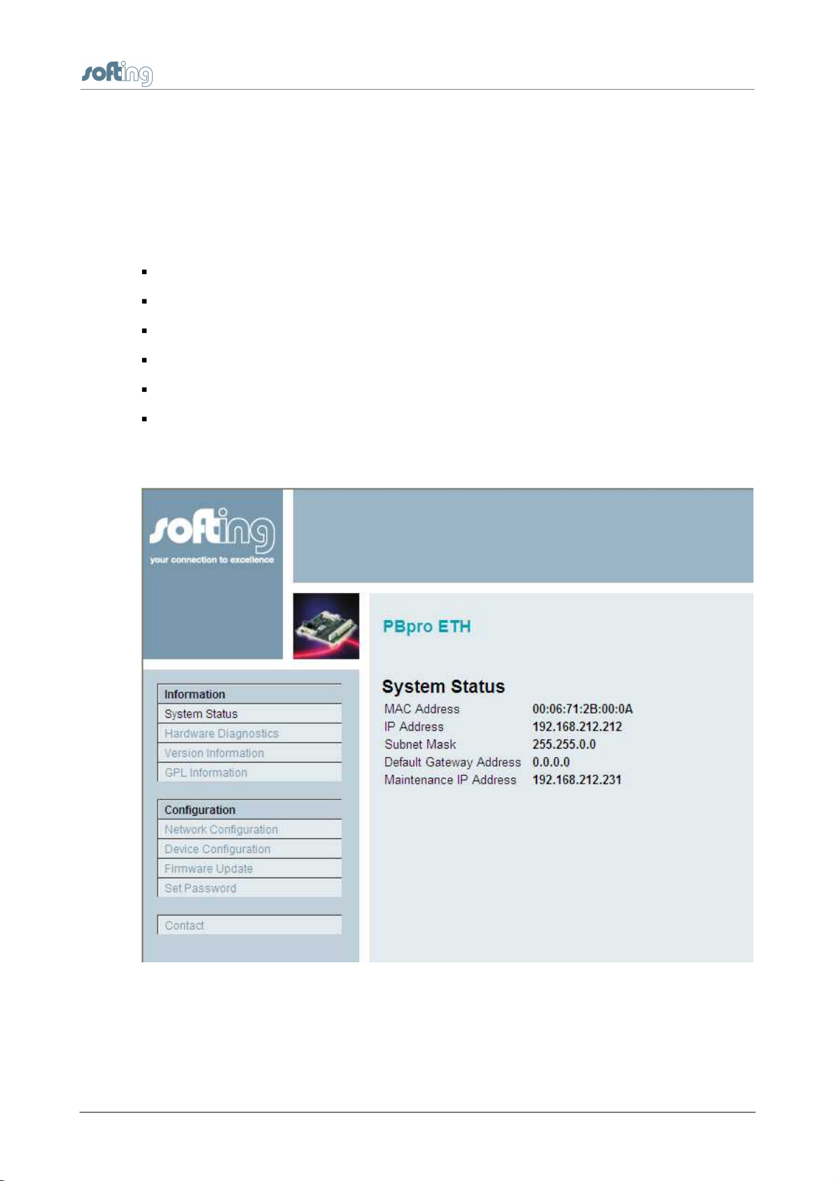
3.2.1 System Status Information
The System Status page indicates the effective IP configuration of the PBpro ETH,
consisting of:
MAC Address fixed Ethernet (MAC) address
IP Address IP address
Subnet Mask IP subnet mask
Broadcast Address IP broadcast address
Default Gateway Address address of the IP gateway to other subnets
Maintenance IP Address IP address of maintenance server (reserved for future use)
The following figure shows an example of the System Status page:
Chapter 3 - PBpro ETH Administration
Figure 2: System Status of the PBproETH
PBpro ETH - User Guide
13
Page 14

Chapter 3 - PBpro ETH Administration
3.2.2 Hardware Diagnostics
During start-up of the device, several hardware components of the system are tested. The
test result is shown in the following example:
Figure 3: Hardware Diagnostics Startup Test Results
14
PBpro ETH - User Guide
Page 15
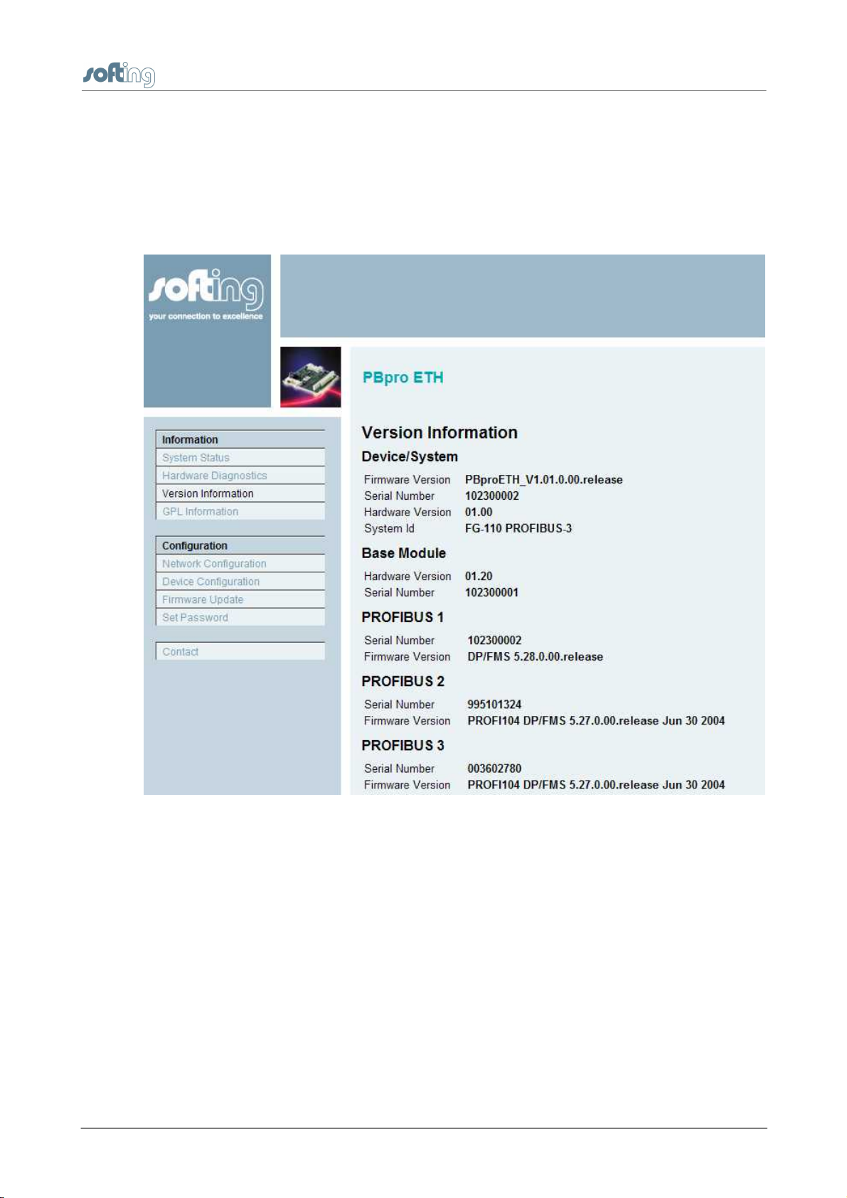
3.2.3 Version Information
The PBpro ETH device consists of a base module with one local PROFIBUS interface for
the first channel and up to three additional PROFIBUS modules for its multi-channel
veraiants. All componentns as well as the entire device are identified by serial numbers
and revisions. The software revisions are indicated too. The following figure shows an
example of the version information:
Chapter 3 - PBpro ETH Administration
Figure 4: Version information
PBpro ETH - User Guide
15
Page 16

Chapter 3 - PBpro ETH Administration
Client Application on PC
Web Browser
Search and Configure
Precondition
valid IP configuration
any Ethernet connection
allowing for broadcast (e.g.
local connection)
Type of connection protocol
HTTP
proprietary UDP based
3.2.4 GPL Information
PBpro ETH partially makes use of open source software. This page shows the
corresponding license information:
Figure 5: GPL License Information
3.3 PBpro ETH network configuration
3.3.1 Overview
PBpro ETH is delivered with a preconfigured IP address (192.168.212.212). Typically it
must be reconfigured and assigned an IP address from your LAN address range.
Furthermore, subnet mask and gateway IP address must be set accordingly. This
information is referred to as "IP configuration".
The IP configuration can be changed via Ethernet by means of a Web Browser (HTTP
protocol) or by the dedicated configuration tool Search and Configure.
The following table shows the possible configuration functions depending on the type of
connection that is used. Those functions will be explained in detail in the following
sections.
16
PBpro ETH - User Guide
Page 17

PBpro ETH"s IP address
192.168.212.212
(default)
any
Login required
yes
yes
Login user name
config (fixed)
config (fixed)
Login user password
config (default)
config (default)
Supported functions:
discovery of
misconfigured devices
network configuration
device configuration
firmware update
modification of password
no
yes
yes
yes
yes
yes
yes
no
no
yes
Table 2: Configuration functions and interfaces
Port 80
for HTTP (PBpro ETH's web pages)
Port 2355
for discovery and configuration using the tool "Search and
Configure"
Port 2356
for controlling PBpro ETH using TCP/IP sockets
Port 2357
for controlling PBpro ETH using the Windows driver
Chapter 3 - PBpro ETH Administration
For proper operation PBpro ETH requires access to the following IP ports:
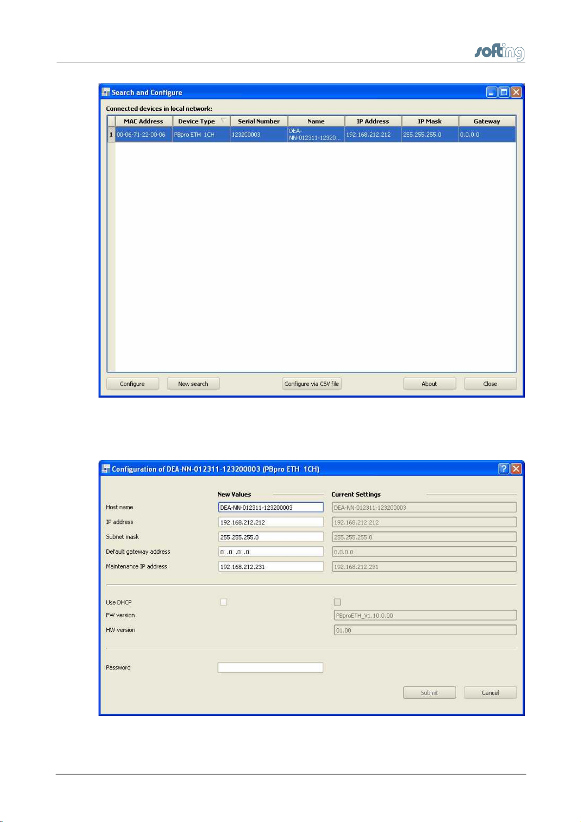
3.3.2 Search and Configure
Use Search and Configure if PBpro ETH's IP address is unknown or does not match the
actual network environment. Search and Configure is part of the PBpro ETH installation
CD and can be installed directly from CD.
When clicking Search and Configure the network will be scanned for Softing devices.
Devices retrieved will be listed with their MAC address, device type, serial number, name,
IP address, subnet mask and gateway:
PBpro ETH - User Guide
17
Page 18
Chapter 3 - PBpro ETH Administration
Figure 6: Search and Configure / Devices
By selecting the device and clicking [Configure] you can modify network parameters of
the PBpro ETH without using its website:
18
Figure 7: Search and Configure / Network parameters
PBpro ETH - User Guide
Page 19

The host name of the device can be set individually. By default it is built from PBpro ETH's
Address range of the
network
Possible number of
networks
Possible number of
hosts per network
Class A
1.xxx.xxx.xx to
126.xxx.xxx.xxx
127 (27)
Approx. 16 million (224)
Class B
128.0.xxx.xxx to
191.255.xxx.xxx
Approx. 16000 (214)
Approx. 65000 (216)
Class C
192.0.0.xxx to
223.255.255.xxx
Approx. 2 million (221)
254 (28)
part number and serial number that can be found on the device's type label, e.g. DEA-NN012311-123200003.
If Use DHCP is activated, the IP settings are not accessible for configuration. In this case
the PBpro ETH when rebooted is assigned appropriate settings by the network's DHCP
server. To find out these new settings PBpro ETH may then be accessed by any web
browser using its host name or a [New search] is conducted using Search and
Configure.
Changing the IP configuration requires the password fitting the selected device. The
default password is "config". It can only be changed via PBpro ETH's web interface.
3.3.3 IP Basics
Following a short introduction to the Internet Protocol (IP) which can be useful in
integrating the PBpro ETH in your Local Area Network (LAN). If you are already familiar
with the basics of the Internet Protocol, you may skip this section.
IP (Internet Protocol)
Chapter 3 - PBpro ETH Administration
The Internet Protocol makes it possible to combine an undefined number of separate
networks to an overall network, allowing data exchange between any two network stations
in any two subnetworks. The physical characteristics of the networks or of the
transmission paths (Ethernet, Token Ring, ISDN, ...) are of no importance. The data will
be transferred to the receiver independently of these differences.
IP addresses
Under IP, every network station has a unique Internet address, often called "IP number".
This Internet address is a 32-bit value which is written, for better readability, in the form of
four decimal numbers (8-bit values) separated by dots (dot notation), e.g. 192.168.1.5. In
the future, 128-bit addresses will be used.
The Internet address consists of net ID and host ID, where the net ID is used to identify the
network and the host ID to identify the station within a network.
The network class defines, which part of the IP address belongs to the net ID and which
one to the host ID. For the addressing of normal networks, three network classes exist:
Class A, Class B and Class C:
Table 3: Key data of the different network classes
PBpro ETH - User Guide
19
Page 20

Chapter 3 - PBpro ETH Administration
The default IP address setting of the PBpro ETH corresponds to class C. The first three
bytes of the IP address are used to identify the network. The last byte is used for
addressing the network station. The complete default IP address is 192.168.212.212.
Assignment of the host ID to the network station and, consequently, the resulting IP
address, can be selected as desired by the network operator (administrator). He must,
however, make sure that an IP address is unique throughout the entire network.
Gateway and subnet mask
The net ID indicates whether the receiver to which a connection is to be established, is
located in the same network as the transmitter. If this part of the IP address is identical for
the transmitter and the receiver, both are located in the same network. If the net IDs are
not identical, the receiver is located in a different network.
The networks can be connected by gateways/routers.
A network can be divided into subnetworks. The net ID defined by the different network
classes is not sufficient for addressing such subnets, however; part of the host ID must
be used for addressing the subnetworks. This means that the net ID is enlarged and the
host ID is reduced accordingly.
The subnetwork defines, which part of the IP address is evaluated as a net ID and which
one as a host ID. Like the IP address the subnet mask is a 32-bit value represented in dot
notation. In binary notation, the part of the subnet mask which corresponds to the net ID is
filled with "1" digits; the part corresponding to the host ID is filled with "0" digits. Example of
a subnet mask is 255.255.255.0
With each data packet to be transmitted, the IP driver compares its own IP address with
that of the receiver. Those bits of the subnet mask which are filled with 0-digits, are
masked off in the IP address. If the evaluated bits of both IP addresses are identical, both
stations are located in the same subnet. If this is not the case, the data packet must be
passed to the gateway or router for transfer to the target network.
Gateways or routers are basically simply computers with two network cards. Ethernet
data packets received on card A are unpacked by the Ethernet driver, and the IP packet
contained in the Ethernet packet is passed to the IP driver. This driver checks whether the
target IP address belongs to the subnet connected to card B and the packet can be
transferred directly, or whether the IP packet must be passed to another gateway. In this
way, a data packet can pass several gateways or routers on its way from one network
station to another.
In addition to routers connecting one Ethernet subnet with another one, there are also
routers which change the physical medium, e.g. from Ethernet to token ring or ISDN.
Broadcast address
20
A broadcast address is used to send a message to all stations in a subnetwork. It is
recommended to use the highest station address in a subnetwork as broadcast address
(i. e. the broadcast address is built by setting all bits of the host ID to "1"). The PBpro ETH
does not use the broadcast address, thus you may omit it.
PBpro ETH - User Guide
Page 21

Chapter 3 - PBpro ETH Administration
Note
Before connecting the PBpro ETH to your LAN network, make sure that its
IP address is not used by another network station.
Note
It is not necessary to configure a default gateway if the computer and the
PBpro ETH are connected to the same subnet.
Note
How to assign a new IP address is described below. You must have
administrator rights.
Host name
An internet-connected machine may be addressed in either of two ways: by its IP address
or by its host name. The host name is a symbolic name (string), which can be memorized
more easily than an IP address. A Domain Name Service (DNS) is needed to translate a
host name to the related IP address.
3.3.4 Establishing a network connection between PC and PBpro ETH
The PBpro ETH is delivered with the preconfigured IP address 192.168.212.212. Connect
the PBpro ETH to your computer. For a direct connection, a cross-linking cable must be
used. This is not necessary if a hub or switch is interconnected.
The description below explains the establishment of a TCP/IP connection to your PBpro
ETH. Such a connection makes it possible to change the preconfigured IP address of the
PBpro ETH.
1. Ask your network administrator for the following information:
o IP address for the PBpro ETH
o Subnet mask
o IP address of the default gateway (if available)
2. Configure your computer in such a way that you have access to the network
192.168.212.0. For this purpose, you may have to assign your host a second IP
address (e.g. IP address = 192.168.212.211, net mask = 255.255.255.0, broadcast =
192.168.212.255).
Assign a second (local) IP address under Windows 7
a. Press the Windows start key or click the Windows Start menu button to open the
start menu. Then select Control Panel.
b. Select Network and Internet.
PBpro ETH - User Guide
21
Page 22

Chapter 3 - PBpro ETH Administration
c. Open Network and Sharing Center.
d. Click Local Area Connection.
e. In the Connection Status window click Properties.
f. In the item connection list select Internet Protocol Version 4 (TCP/IPv4).
g. Click Properties.
h. In the General dialog, the regular (first) IP address, the subnet mask and the
standard gateway are shown.
i. Click Advanced to add a second IP address. Then click Add in the IP Addresses
dialog.
j. Enter the IP address and the subnet mask.
k. Click Add.
l. Then confirm all open dialogs with [OK].
Assign a second (local) IP address under Windows XP
a. Select Start Settings Control Panel. Double-click the icon Network and
Dial-up Connections.
b. Double-click LAN connection.
c. Click Properties.
d. Select the entry Internet Protocol (TCP/IP) and click Properties.
e. In the Internet Protocol (TCP/IP) Properties dialog, the regular (first) IP address,
the subnet mask and the standard gateway address are shown. To add a second
IP address click the "Advanced..." button.
f. Click Advanced to add a second IP address. Then click Add in the IP Addresses
dialog.
g. Enter the IP address and the subnet mask.
h. Click Add.
i. Then confirm all open dialogs with [OK]
These settings are only available if DHCP is disabled.
3. Try to ping the PBpro ETH. Open a command prompt and enter the following
command: "ping 192.168.212.212". The PBpro ETH should respond.
If it does not respond, check whether the PBpro ETH is correctly connected to the LAN
and whether it is switched on. Check also whether your computer is correctly
connected to the LAN by a cable. Check whether the computer has been configured
with a valid IP address from the subnet 192.168.212.0. Try to ping the second (local)
IP address of your computer (in the example, 192.168.212.211). If the local computer
does not respond, the second IP address has not been initialized correctly.
22
4. If you have access to the PBpro ETH from your computer, you can change its network
configuration with a Web browser.
PBpro ETH - User Guide
Page 23

Chapter 3 - PBpro ETH Administration
3.3.4.1
3.3.4.2
Web based configuration and firmware update
After an IP connection between PC and PBpro ETH has been set up as described in the
previous sections, you may access the PBpro ETH from your PC by means of a Web
Browser (e. g. Microsoft Internet Explorer).
Start your browser with the URL http://192.168.212.212 (factory default for Ethernet
connection) or the currently assigned IP address of the PBpro ETH respectively. The
page System Status will be displayed. The menu bar offers four information pages, four
configuration pages and the contact page.
The configuration pages offer the following functions
Network Configuration
Device Configuration
Firmware Update
Set Password
All configuration pages require a login name and a password to execute the functions. The
login name is "config". The password is "config" by default, but may be changed.
Network configuration
The PBpro ETH is shipped with the following default IP configuration:
Login: config
Password: config
Host Name: <part number>-<serial number> (see type label)
IP Address: 192.168.212.212
Subnet Mask: 255.255.255.0
Maintenance IP Address: 192.168.212.231 (for future use only)
You may change the IP configuration according to your needs. IP address and subnet
mask must be present in any case. You may leave the host name empty. It is reserved for
future use and has no meaning in the current release. It is not necessary to configure a
default gateway, if the computer and the PBpro ETH device are connected to the same
subnet.
PBpro ETH - User Guide
23
Page 24

Chapter 3 - PBpro ETH Administration
Note
If you change the IP address of the PBpro ETH, the IP connection between
PC and PBpro ETH will be lost. You have to use the new IP address to
reestablish web access to the Pbpro ETH.
If an inconsistent network configuration is used, it may be impossible to
connect to the PBpro ETH again.
Figure 8: Network Configuration
When the entries are complete, enter the password and click the [Submit] button. The
input values will be checked for consistency.
3.3.4.3
Device configuration
The first PROFIBUS channel of a multi-channel device and the single channel variant of
PBpro ETH always have PROFIBUS DP/FMS Master functionality.The additional channels
of a multi-channel device (PROFIBUS2, PROFIBUS3, …) can operate either as DP/FMS
Master or as DP Slave device.
24
PBpro ETH - User Guide
Page 25

Chapter 3 - PBpro ETH Administration
Figure 9: Device Configuration
To change the device configuration, select the desired operating mode of a PROFIBUS
channel and click the [Submit] button. The successful completion of the change process
is indicated by the message Success in the browser window.
3.3.4.4
Firmware update
If a new version of the device's firmware becomes available it can be stored in the device
using this configuration page.
Click the [Select] button to open a file selector box. Here you can choose the firmware file
to be downloaded. You may want to reset the device configuration to factory defaults. The
IP configuration will not be changed.
PBpro ETH - User Guide
25
Page 26

Chapter 3 - PBpro ETH Administration
Click Download Firmware and Reboot to start the download process. Firmware
download and flash memory update take between one and two minutes. The successful
completion of the update process is indicated by the message Success in the browser
window.
3.3.4.5
Set password
This web page allows for changing the password. Enter the current password first. Then
enter the new password twice.
3.3.5 Configuring access to PBpro ETH on a Windows PC
3.3.5.1
3.3.5.2
Install software
The PBpro ETH software is part of the "PBpro ETH Installation CD".
1. Insert the CD into your CD drive.
2. If Autorun is enabled on your system, the startup page is opened automatically.
3. If Autorun is disabled, open an Explorer window, select your CD drive and double-click
the file start.exe.
The CD contains various information and software. Make sure to install at least the
"Drivers and Software Development Kit (SDK) for Windows".
Configure driver
Before application programs can use PBpro ETH, you need to configure the device for
operation:
1. Click Start All Programs Softing PROFIBUS Drivers and API
Runtime System Driver Configuration.
26
PBpro ETH - User Guide
Page 27
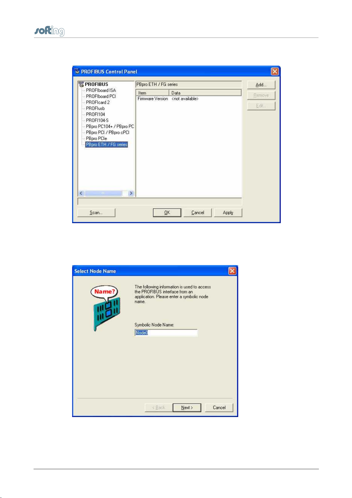
2. Select PBproETH / FG series and click Add:
Chapter 3 - PBpro ETH Administration
Figure 10: Device Configuration
3. A dialog is opened allowing to enter/modify symbolic naming of a PROFIBUS channel:
Figure 11: Symbolic Node Name
PBpro ETH - User Guide
27
Page 28
Chapter 3 - PBpro ETH Administration
4. You may change the default name Node<n> according to your needs.
5. Click [Next].
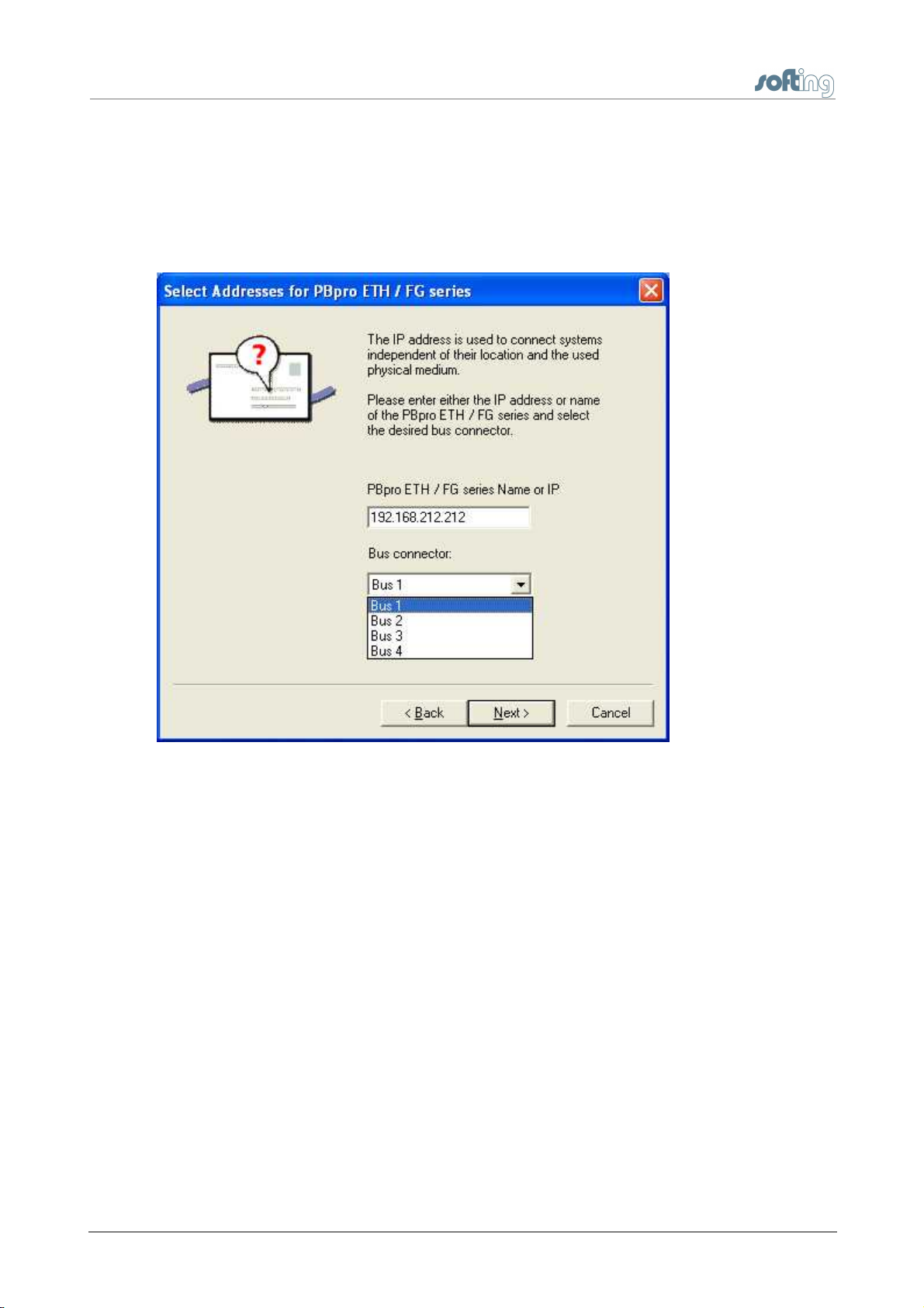
6. In the next step you need to identify the the PBpro ETH either by its IP address or by
its host name and select the assigned connection. For single channel devices always
select "Bus 1".
Figure 12: IP address
7. Click [Next].
28
PBpro ETH - User Guide
Page 29

8. In the next step you need to adjust timeout values:
Chapter 3 - PBpro ETH Administration
Figure 13: Timeout parameters
Following the meaning of the particular parameters:
Timeout for Connect Time control interval for monitoring the connection
establishment to the PBpro ETH
Max Idle Time Time control interval to monitor the connection
DP Update Interval Update interval time for exchanging the DP process
image. The process image will only be transferred if data
have changed
Forced DP Update Interval Forced update interval time for exchanging the DP
process image (regardless whether data have changed or
not)
PBpro ETH - User Guide
29
Page 30

Chapter 3 - PBpro ETH Administration
9. Click [Finish] to complete the configuration.
10. A green check mark in front of the symbolic name appears to indicate the correct
channel definition:
Figure 14: Configuration completed
11. If you need to configure further channels, repeat the steps from above.
12. Once defined a channel can be used by application programs either via its symbolic
name (e.g. "Node0") or via its unique interface number.
Examples for ready to use software are Softing's:
PROFIdtm (free gateway DTM for FDT based parameterization and asset
management tools)
PROFIBUS Configurator
PROFIBUS OPC server
Sample programs (supplied with the SDK as optional part beside the driver
installation)
3.3.6 Reset to factory settings
If you cannot get access to the PBpro ETH, you may want to reset the device to the
default factory settings. For instance this may be necessary if the configuration password
got lost.
30
PBpro ETH - User Guide
Page 31

Chapter 3 - PBpro ETH Administration
Important
Reset to factory settings is an ultimate means to regain access to a
device with an unknown password. The internal reset button is a very small
and sensitive component not meant for regular use. Use this button with
extreme care and only in case of necessity. Be careful not to push too hard.
This may damage the button and can also lead to permanent failure of the
PBpro ETH. Such damages are not covered by warranty.
To assure that only authorized personnel may perform a reset to factory settings this
action requires physical access to the PBpro ETH.
To reset, proceed as follows:
1. Remove power from the PBpro ETH
2. Carefully insert the tip of a ball pen into the hole labeled "Reset".
Figure 15: Activating the internal reset button with a ball pen (shown at an open
device)
3. While gently holding down the ball pen reassert power to the PBpro ETH.
4. After a few seconds an LED (single channel device:"RUN" , multi channel device:
"CON2") starts flashing 10 times per second.
5. As soon as the LED starts flashing you can remove the ball pen.
6. The reset process then takes roughly one minute with various LEDs flashing.
7. Finally, the "RUN" LED will shine solid green, indicating that PBpro ETH is operational.
PBpro ETH - User Guide
31
Page 32

Chapter 4 - Technical Data
Order Code
(product including
device, CD, manual)
DEL-NN012311
DEL-NN012312
DEL-NN012313
DEL-NN012314
Number of PROFIBUS
Channels
12 3
4
Part Number
(of the device itself)
DEA-NN-
012311
DEA-NN-
012312
DEA-NN-
012313
DEA-NN-
012314
Supply Voltage
(direct current)
+24V DC
Supply Voltage
Tolerance
±20% (incl. ripple)
Typical Current Consum
ption During Operation
0.2 A
0.3 A
0.4 A
0.5 A
Mounting
TS35 DIN carrier rail (EN 50022)
Dimensions (W x H x D
in mm)
47 x 134 x
111
111 x 134 x 111
Weight (approx. in kg)
0.3
0.6
0.7
0.8
Degree Of Protection
IP 20
Ambient Temperature
(operation)
0°C to 55°C
Ambient Temperature
(storage)
-20°C to 70°C
Relative Air Humidity
max. 90% at +25°C (non-condensing)
4 Technical Data
The following summary provides you with the most important technical data:
32
PBpro ETH - User Guide
Page 33

5 Declarations by the manufacturer
A Declaration of Conformity in compliance with the above standards has been
made and can be requested from Softing Industrial Automation GmbH.
Note
To fulfill the EMC requirements, the other components of your installation (DC
adapter, Industrial Ethernet devices, etc.) also have to meet the EMC
requirements. A shielded cable must be used. In addition, the cable shield
must be grounded properly.
CAUTION
This is a Class A product. In a domestic environment this product may cause
radio interference in which case the user may be required to take adequate
measures!
FCC
This equipment has been tested and found to comply with the limits for a
Class A digital device, pursuant to part 15 of the FCC Rules. These limits are
designed to provide reasonable protection against harmful interference when
the equipment is operated in a commercial environment. This equipment
generates, uses, and can radiate radio frequency energy and, if not installed
and used in accordance with the instruction manual, may cause harmful
interference to radio communications. Operation of this equipment in a
residential area is likely to cause harmful interference in which case the user
will be required to correct the interference at his own expense.
VCCI
Additional tests have been performed successfully proving compatibility with
the requirements set forth by VCCI.
ROHS
The PBpro ETH device is ROHS compliant.
This device complies with the requirements of the EC directive 2004/108/EG
"Electromagnetic Compatibility" (EMC directive). It meets the following requirements:
Emission:
- EN 55011 Limits and methods of measurement of radio disturbance
characteristics of industrial, scientific and medical (ISM) radio
frequency equipment, group 1, class A
- EN 55022 Information technology equipment; Radio disturbance
characteristics; Limits and methods of measurement, class A
- EN 61000-6-4 Electromagnetic compatibility (EMC); Part 6-4: Generic standard –
Emission standard for industrial environments
Immunity:
- EN 61000-6-2 Electromagnetic compatibility (EMC); Part 6-2: Generic standard Immunity for industrial environments
Chapter 5 - Declarations by the m anufacturer
PBpro ETH - User Guide
33
Page 34

Chapter 5 - Declarations by the m anufacturer
WEEE
Electrical and electronic equipment must be disposed of separately from
normal waste at the end of its operational lifetime.
34
PBpro ETH - User Guide
Page 35

This page is intentionally left blank.
Page 36

Softing Industrial Automation GmbH
Richard-Reitzner-Allee 6
85540 Haar / Germany
Tel: + 49 89 4 56 56-0
Fax: + 49 89 4 56 56-488
Internet: http://industrial.softing.com
Email: info.automation@softing.com
Support: support.automation@softing.com
 Loading...