

Page 1

Quick Startup Guide
FG-200 HSE/FF Modbus
Version: EN-102018-1.31
© Softing Industrial Automation GmbH
Page 2

Disclaimer of liability
The information contained in these ins tructions corresponds to the technical status at the time of
printing of it and i s pas sed on with the best of our knowledge. The information in these
instructions is in no event a basis for warranty claims or contractual agreements concerni ng the
described products, and may especially not be deemed as warranty concerning the quality and
durability pursuant to Sec. 443 German Civil Code. We reserve the right to make any alterations or
improvements to these instructions without prior notice. The actual design of products may
deviate from the information contained in the instructions if technical al terations and product
improvements s o require.
Softing Industrial Automation GmbH
Richard-Reitzner-Allee 6
85540 Haar / Germany
http://industrial .softing.com
+ 49 89 4 56 56-0
+ 49 89 4 56 56-488
info.automation@softing.com
support.automation@softing.com
Scan the QR code to find the latest documentation on the product
web page under Downloads.
Page 3

Table of Contents
Chapter 1 ................................................................................... 6About this guide
................................................................................................................ 61.1 Read me first
................................................................................................................ 61.2 Target audience
................................................................................................................ 61.3 Typographic conventions
................................................................................................................ 71.4 Document feedback
Chapter 2 ................................................................................... 8About FG-200 HSE/FF Modbus
................................................................................................................ 82.1 Intended use
................................................................................................................ 82.2 Scope of delivery
................................................................................................................ 92.3 System requirements
................................................................................................................ 92.4 Safety precautions
Chapter 3 ................................................................................... 11Installation
................................................................................................................ 113.1 Hardware ins tallation
Mounting and dis mounting 3.1.1
.................................................................................................. 11
Connection diagram 3.1.2
.................................................................................................. 13
Connecting the power suppl y 3.1.3
.................................................................................................. 14
Connecting to the network 3.1.4
.................................................................................................. 15
Modbus serial connection 3.1.5
.................................................................................................. 17
FG-200 redundancy 3.1.6
.................................................................................................. 17
FF-H1 interface connection 3.1.7
.................................................................................................. 20
Powering up the device 3.1.8
.................................................................................................. 22
Adding a second FG-200 for redundancy 3.1.9
.................................................................................................. 22
................................................................................................................ 233.2 Software instal lation
Tabl e of Con tents
© Softing Industrial Automation GmbH 3
Page 4

Tabl e of Con tents
Chapter 4 ................................................................................... 24Configuration
................................................................................................................ 244.1 Confi guring the IP address
................................................................................................................ 254.2 Setting up a ComConf project
Chapter 5 ................................................................................... 26Status indicators - LEDs
................................................................................................................ 275.1 PWR - power supply
................................................................................................................ 275.2 Device LED statuses in stand-a lone mode
................................................................................................................ 285.3 RUN/ERR/RDL - LED statuses in redundant mode
................................................................................................................ 325.4 H1 channel status indicators
Chapter 6 ................................................................................... 33Technical data
................................................................................................................ 336.1 Specifications
................................................................................................................ 346.2 Installation positions
Chapter 7 ................................................................................... 36European and International Approval
Chapter 8 ................................................................................... 37North American Approval
Chapter 9 ................................................................................... 38Declaration of conformity
© Softing Industrial Automation GmbH4
Page 5

This page is intentionally left blank.
© Softing Industrial Automation GmbH 5
Page 6

FG-200 HSE/FF Modbu s - Qui ck Startup Gu ide
Keys, buttons, menu items, commands and
other elements involving user interaction are
set in bold font and menu sequences are
separated by an arrow
Open Start Control Panel Programs
Buttons from the user interface are enclosed
in brackets and set to bold typeface
Press [Start] to start the application
Coding samples, file extracts and screen
output is set in Courier font type
MaxDlsapAddressSupported=23
Fil e names and directories are written in
italic
Device description fi les are located in C:
\<Application name>\delivery\software
\Device Description files
1
About this guide
1.1 Read me first
Please read this guide carefull y before using the device to ensure safe and proper us e.
Softing does not ass ume any liabil ity for damages due to improper installa tion or
operation of this product.
1.2 Target audience
This Qui ck Startup Guide is i ntended for experienced operation personnel and network
specialists responsible for configuring and maintai ning field devices in process
automation networks. Any person using an FG-200 HSE/FF Modbus must have read and
fully understood the safety requirements and working ins tructions in this guide.
1.3 Typographic conventions
The following conventions are used throughout Softing customer documentation:
6 © Softing Industrial Automation GmbH
Page 7

Chapte r 1 - Abo ut thi s gu ide
CAUTION
This symbol indicates a potential ly hazardous si tuation which, if not avoided,
may result in minor or moderate injury
Note
This symbol is used to call attention to notable information that should be
followed during installation, use, or servi cing of this device.
1.4 Document feedback
We would li ke to encourage you to provide feedback and comments to help us improve the
documentation. If you have a PDF copy of thi s document si mply write your comments and
suggestions to the PDF fil e usi ng the editing tool i n Adobe Reader and email your feedback
to support.automation@softing.com.
If you prefer to write your feedback directly as an email, pl ease include the following
information with your comments:
document name
document versi on (as shown on cover page)
page number
© Softing Industrial Automation GmbH 7
Page 8

FG-200 HSE/FF Modbu s - Qui ck Startup Gu ide
Note
The FG-200 is availabl e in two vari ants. They have identical technical
specifi cations. Their only di fferentiating characteris tic is their mount direction
that is mirrored, i.e. rotated by 180°.
2
About FG-200 HSE/FF Modbus
The Softing FG-200 HSE/FF Modbus is a gateway connecting Modbus RTU, Modbus TCP or
FOUNDATION fieldbus High Speed Ethernet (HSE) to FOUNDATION fieldbus H1 field devices.
It provides fast access to process data, while maki ng use of FOUNDATION Fieldbus
adva ntages s uch as reduced cabli ng, central field device parametrization, comprehensive
diagnos tics or intrinsicall y safe device segments. For s imple installation it is compatible
with the R. STAHL bus-Carrier Series 9419 and Fi eldbus power suppli es Seri es 9412.
2.1 Intended use
The FG-200 ca n be used for integrating up to four FF H1 links into a Modbus control system
(TCP or RTU) or for communication between FF H1 devices and FF HSE network. The gateway
can be operated in both hazardous and non-hazardous areas. Any other use is not
intended. Follow the instructions in this guide on how to use the FG-200.
2.2 Scope of delivery
The delivery of this gateway includes the foll owing parts:
FG-200 HSE/FF Modbus device
CD including ComConf, PACTware firmware and manuals
Quick Startup Guide
IP a ddress label
8 © Softing Industrial Automation GmbH
Page 9

Chapte r 2 - Abo ut FG-200 HSE/FF Modbus
2.3 System requirements
24V power supply
power condi tioner
PC with operating system Windows 7 or Windows 8.1 (both 32 bi t or 64 bit supported)
Web browser (Microsoft Internet Explorer version 8.0 or higher, Mozil la Fi refox version
versi on 35 or higher)
2.4 Safety precautions
Use in hazardous areas
The FG-200 is an electrical equipment with degree of protection Ex nA, approved for use in
Zone 2 hazardous areas or i n the safe area. The four FF-H1 interfaces are designed
according to the protection method Ex ic. Onl y certified circuits with an accordi ng
protection method shall be connected to these FF-H1 interfaces.
© Softing Industrial Automation GmbH 9
Page 10

FG-200 HSE/FF Modbu s - Qui ck Startup Gu ide
Before setting the FG-200 i nto operation, the corresponding field has to be
maked (e.g. if the device is used in an IC environment, mark the upper field on
the type label).
Use an appropri ate permanent pen for si gning, e.g. an etching pen.
More than one marking is not allowed. If you need a second marking, you must
replace the exis ting equipment with a new one.
An equipment which has been operated under non-intri nsical ly safe
condi tions i s no longer permitted to be used under intrinsi cally safe
condi tions.
CAUTION
During operation, the device's surface wil l be heated up. Avoid di rect contact.
When servicing, turn off the power supply and wai t until surface has cooled
down.
Note
Do not open the housing of the FG-200. It does not contain any parts that need
to be maintained or repaired. In the event of a fault or defect, remove the device
and return it to the vendor. Opening the device wil l void the warranty!
Special hints for safe use
The FG-200 HSE/FF Modbus is only approved for intended and appropriate use. In ca se of
noncompliance, the warranty and manufacturer’s l iabi lity do no longer apply!
10 © Softing Industrial Automation GmbH
Page 11

Chapte r 3 - Ins tal lation
Note
With an ambient temperature above 55 °C at the place of installation it is l ikely
that the temperatures of connecting cables wil l increase if the cables are
install ed in an unfavourable position. In such cases, measure the temperature
to ensure that the service temperature of the cables i s not exceeded (i.e. 80 °C),
or use cables sustaining high temperatures of at least 90 °C.
Note
Make sure the FG-200 is mounted in a manner that the power supply
disconnecting device or interrupt faci lity can always be reached easil y.
Note
Depending on the installation pos ition, the maxi mum ambient operating
temperature may differ. Refer to Technical Data for detai led information.
Installation and inspection
Instal lation and inspection must be carried out by quali fied personnel only
(personnel qual ified accordi ng to the German standard TRBS 1203 or similar
(Technical Regulations for Operational Safety). The defini tion of terms can be
found in IEC 60079-17.
3
Installation
3.1 Hardware installation
3.1.1 Mounting and dismounting
33
© Softing Industrial Automation GmbH 11
Page 12

FG-200 HSE/FF Modbu s - Qui ck Startup Gu ide
1. Hook the upper notch of the cut-out on the
back of the FG-200 into a 35 mm DIN rail .
2. Press the FG-200 down towards the rail
until it sl ides into place over the lip of the
locking bar.
Note
Do not put stress on the device by bending or tors ion.
1. Slide a screwdri ver diagonal ly under the
housing into the locki ng bar.
2. Lever the screwdriver upwards, pull the
locking bar downwards - without tilting the
screwdriver - and move the gateway upwards
off the rai l.
Mounting
Dismounting
12 © Softing Industrial Automation GmbH
Page 13

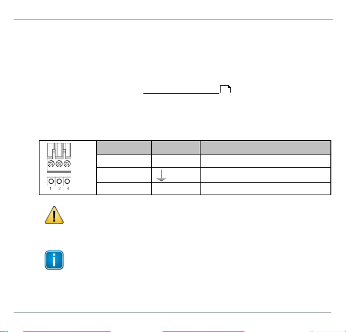
3.1.2 Connection diagram
The following connection diagram shows the physical interfaces of the FG-200.
Chapte r 3 - Ins tal lation
© Softing Industrial Automation GmbH 13
Page 14
FG-200 HSE/FF Modbu s - Qui ck Startup Gu ide
Pin
Signal
Description
1
GND
Ground
2
Functional earth
3
L+
Positive supply voltage
CAUTION
The Functional Earth (FE) connection of the device has to be connected at low
inductance with the Protective Earth (PE) of the system.
Note
As indicated in the connection diagram, the power can be appl ied alternatively
by a speci al DIN rail connector (Rail Power Suppl y). For further information
contact Softing Industri al Automation.
3.1.3 Connecting the power supply
1. Connect the FG-200 to a 24 V DC power supply.
2. Use different or redundant power supplies for redundant FG-200s.
3. Turn on the power supply. The boot process takes approx. 50 seconds. For indica tion
of proper operation of a FG-200 acting in non-redundant mode or as pri mary device
in redundant mode refer to Status i ndicators - LEDs .
The suppl y voltage (18 VDC .... 32 VDC) is connected by a 3-pole terminal block. The power
supply is connected to the plug connector vi a flexi ble wires with a cross s ection of 0.75 to
1.5 mm². The ground connection wire must have a cross section of 1.5 mm².
14 © Softing Industrial Automation GmbH
26
Page 15

Chapte r 3 - Ins tal lation
Note
When using the FG-200 as li nking device you can broadcast High Speed Ethernet
(HSE) and Modbus TCP over the same Ethernet port.
3.1.4 Connecting to the network
1. Connect the FG-200 to the Modbus TCP network to one of the two Ethernet ports (ETH1
or ETH2).
2. Connect each link of your FOUNDATION fieldbus H1 network via a power conditioner
to a Fieldbus Channel port of your gateway (CH0 to CH3).
FG-200 with redundancy connection
© Softing Industrial Automation GmbH 15
Page 16

FG-200 HSE/FF Modbu s - Qui ck Startup Gu ide
Note
Your FG-200 cannot operate in both Modbus TCP and Modbus RTU mode at the
same time.
Note
When you connect your FG-200 to a Modbus RTU Mas ter you cannot operate
the device in redunda ncy mode.
FG-200 with Modbus connection
16 © Softing Industrial Automation GmbH
Page 17

Chapte r 3 - Ins tal lation
Pin
Signal
Description
6RXReceiver eXchange
5TXTrans mitter eXchange
4
GND
Ground
Note
If you are working with two FG-200 in redundant mode, the seri al connection
cannot be used (s ee next Section).
Note
As the interface is not galvanicall y isolated make sure that there is no potential
difference between the two connected devices.
3.1.5 Modbus serial connection
When connecting the FG-200 via s erial connection (RTU) use the connector from your
delivery with the following pin ass ignment:
3.1.6 FG-200 redundancy
If you intend to use two FG-200s as a redundant set, connect the redundancy link
interfaces (RDL) of both FG-200s (primary and secondary) by a cable before you power up
the devices. If the redundancy l ink is not installed before start-up, the FG-200 wil l operate
in non-redundant mode.
© Softing Industrial Automation GmbH 17
Page 18

FG-200 HSE/FF Modbu s - Qui ck Startup Gu ide
Pin
Signal
Description
6RXReceives data from redundant device
5TXTrans mits data to redundant device
4
GND
Ground
Note
The receive (RX) and transmit (TX) signals must be cross-l inked.
The maximum cabl e length is 0.5 m according to EMC requirements. The pin as signment is :
Do not power up devices when serial link is missing
If the two FG-200 s forming a redundant set are powered while the serial link is missing,
both devices will behave like independent, non-redundant Pri mary Devices. If they
operated in redundant mode before and therefore have identical configuration
information, both will use the same H1 node address es, which will cause problems on the
H1 links. The ERR (error) LED will blink. In thi s case, remove the power, install the serial
li nk and apply the power again.
18 © Softing Industrial Automation GmbH
Page 19

Chapte r 3 - Ins tal lation
Primary device vs. secondary device
When using a redundant set of two FG-200 s , the device which is powered first will operate
as primary device. If both devices are powered at the same time, the one with the lower IP
address will operate as primary device.
Removing the power supply
Before you remove the power supply from the primary device make sure the secondary
device is operational . In a redundant set of FG-200s, removing the power suppl y, the
Ethernet cable or the redundancy l ink interface cabl e from the primary device caus es a
redundancy change-over. Before doing so, make sure that the secondary device is
operational (and not still booting due to a prior change-over). Otherwise the system breaks
down or the configuration i nformation might get lost. Therefore wait at least one minute
between such checks .
© Softing Industrial Automation GmbH 19
Page 20

FG-200 HSE/FF Modbu s - Qui ck Startup Gu ide
CH1
Pin
Signal
Description
7+Fieldbus +
8SFieldbus shield
9-Fieldbus -
CH2
Pin
Signal
Description
10+Fieldbus +
11SFieldbus shield
12-Fieldbus -
3.1.7 FF-H1 interface connection
Connect the H1 li nks to the terminal blocks of the H1 interfaces. Since the FG-200 does not
provi de power to the H1 links, a power condi tioner and a bus termination is required for
each H1 link. When using a redundant set of two devices, make sure to connect each H1
li nk to the same channel (CH 1 .. CH 4) on both FG-200s.
The FG-200 provides four Founda tion Fieldbus H1 i nterfaces. These interfaces are named
CH1 to CH4 and are used to connect an FF-H1 bus to the FG-200.
FF H1 bus line channel 1
FF H1 bus line channel 2
20 © Softing Industrial Automation GmbH
Page 21

Chapte r 3 - Ins tal lation
CH3
Pin
Signal
Description
13+Fieldbus +
14SFieldbus shield
15-Fieldbus -
CH4
Pin
Signal
Description
16+Fieldbus +
17SFieldbus shield
18-Fieldbus -
Note
The fieldbus shield is not connected directly to functiona l earth. For EMC
reasons, it is onl y connected via a capacitor. If a direct connection to
functional earth or protective earth is required, you need to implement this
separately.
FF H1 bus line channel 3
FF H1 bus line channel 4
© Softing Industrial Automation GmbH 21
Page 22

FG-200 HSE/FF Modbu s - Qui ck Startup Gu ide
Hint
Refer to Section FG-200 redundancy for more information on the
redundancy concept.
3.1.8 Powering up the device
Turn on the power supply. The boot process takes a few seconds. For indication of proper
operation of a FG-200 refer to Status indica tors - LEDs .
26
3.1.9 Adding a second FG-200 for redundancy
For adding a second FG-200 to an already commiss ioned FG-200 that is operating in the
role "Primary, no backup", the foll owing steps are required:
1. Set the IP configuration (IP address and subnet mask) of the second FG-200 usi ng the
same IP subnet as the primary device (see Configuring the IP address ).
2. Connect the H1 li nks to the terminal blocks of the H1 interfaces. Make sure to connect
each H1 link to the same channel (CH 1 .. CH 4) on both FG-200s.
3. Connect the second FG-200 to the Ethernet switch or hub.
4. Connect both RDL interfaces as mentioned in Section FG-200 redundancy.
5. Connect the second FG-200 to a 24 V DC power supply. Use different or redunda nt
power supplies for redundant FG-200s .
6. After turni ng on the power supply the boot process takes approx. 50 seconds.
7. The second FG-200 will take over the configuration data from the primary device and
will start operation in the role "secondary". For more detail s about proper operation
as a secondary device see also the Status indicators - LEDs .
17
26
24
17
22 © Softing Industrial Automation GmbH
Page 23

Chapte r 3 - Ins tal lation
3.2 Software installation
When you i nstall a Softing product for the first time, you will be asked in a di alogue
window if you trust the publi sher. Activate the option Always trust software from Softing
AG if you do not want to be asked in s ubsequent instal lations and select [Install] to start
the installation.
1. Insert the CD "Gateways for Process Industries" into the CD drive.
a. If Autorun is enabled on your system, the startup page is opened.
b. If Autorun i s disabled, open an Explorer window, select your CD drive and
double-click the file start.exe in the CD's root directory.
2. Select Installation of FG-200 Software and Documentation in the startup page.
3. Select the ins tallation setup fil es required.
4. Instal l the SearchAnd Configure software.
With the SearchAndConfigure function you will be abl e to detect and modify device IP
addresses. See the User Guide for more detail s.
5. Instal l PACTware if no other FDT frame application is used.
PACTware and the Softing FFdtm will be installed.
6. Instal l FFdtm if you prefer using a different FDT frame application such as FieldCare,
FieldMate or others to allow usi ng a CommDTM in another FDT frame appli cation. See
the User Guide for more details .
© Softing Industrial Automation GmbH 23
Page 24

FG-200 HSE/FF Modbu s - Qui ck Startup Gu ide
Note
Before connecting the FG-200 to your LAN network, make sure that its IP
address is not used by another network station.
To assign a new IP address to your PC, you must have adminis trator rights.
4
Configuration
When your PC and FG-200 have an IP connection, start a web browser to access the
gateway from your PC.
4.1 Configuring the IP address
The FG-200 is deli vered with the pre-confi gured IP address 192.168.0.10.
1. Open a browser (e.g. Internet Explorer or Firefox).
2. Enter the URL address 192.168.0.10 and press Enter.
3. Login with the foll owing data:
login name: administrator
login password: fgadmin
4. Select Configuration Settings Internet Protocol.
5. Change IP Address and Subnet Mask.
6. Cli ck [Change Settings and Reebot]
7. The FG-200 performs a reboot.
24 © Softing Industrial Automation GmbH
Page 25

Chapte r 4 - Configuration
4.2 Setting up a ComConf project
For information on how to set up a project in the Communication Configuration Tool and
working with the FG-200 web server interface refer to the User Guide on CD or download
the lastest document version from the product page. Scan QR code on back page for direct
access .
© Softing Industrial Automation GmbH 25
Page 26
FG-200 HSE/FF Modbu s - Qui ck Startup Gu ide
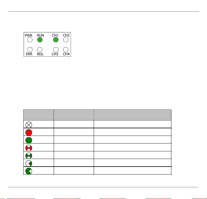
Symbol
Color
Lighting
none
off
red
permanent
green
permanent
red
fla shing
green
fla shing
green
fla shing sl owly (0.5 Hz)
green
fla shing quickly (5 Hz)
5
Status indicators - LEDs
The FG-200 is equipped with eight LEDs on its front side:
PWR stands for power supply
RUN stands for running
ERR stands for error
RDL stands for redundancy link
CH1 to CH4 stands for H1 channel 1 to H1 channel 4
The LEDs may be on permanently or fl ash i n different colors and frequenci es. We use the
following symbols:
26 © Softing Industrial Automation GmbH
Page 27
Chapte r 5 - Sta tus ind icators - LEDs
permanent green
24V DC power suppl y is ok
off
no power supply
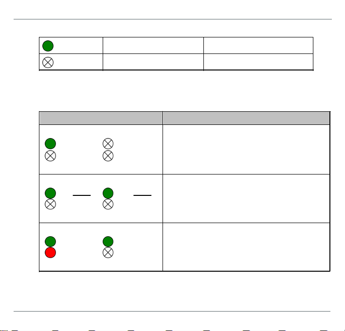
LEDs
Meaning
PWR
RUN
green
ERR
RDL
Startup phase (approximately 7 seconds)
During this phas e redundancy role is determined.
PWR
RUN
green
green
ERR
RDL
Non redundant device, ready.
The device is operational; it is not part of a
redundant set.
PWR
RUN
green
green
red
ERR
RDL
Permanent hardware fault detection during
startup.
A fatal error has been detected.
5.1 PWR - power supply
5.2 Device LED statuses in stand-alone mode
The following table shows possible LED combinations i n stand-a lone mode:
© Softing Industrial Automation GmbH 27
Page 28

FG-200 HSE/FF Modbu s - Qui ck Startup Gu ide
fla shing
green
redundancy l ink communication is ok (triggered by redundancy
li nk packets)
red
li nk communication interrupted or aborted (broken down)
off
no link communication at all
LEDs
Meaning
PWR
RUN
green
ERR
RDL
Start–up phase (approx. 7 seconds )
During this phas e redundancy role is determined.
PWR
RUN
green
green
ERR
RDL
Non redundant device, ready.
The device is operational; it is not part of a
redundant set.
Primary Device is redundant set.
The device is operational, acting as Primary Device
in a redundant set. The secondary device is ready
PWR
RUN
green
green
red
ERR
RDL
Permanent hardware faul t detection duri ng startup.
A fatal error has been detected. Possible failure
coul d be a missi ng Ethernet connection.
5.3 RUN/ERR/RDL - LED statuses in redundant mode
The redundancy link LED is used to indicate if traffic via the serial line is performed. It will
fla sh green if a vali d message is received. It will switch to red if serial communication i s
lost and it will be off if no serial response has been received after startup.
28 © Softing Industrial Automation GmbH
Page 29

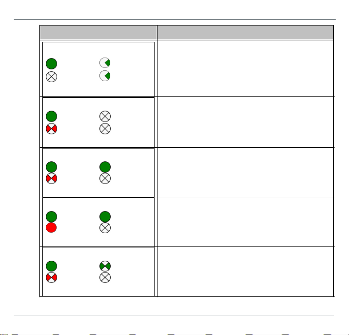
Chapte r 5 - Sta tus ind icators - LEDs
LEDs
Meaning
PWR
RUN
green
green
red
ERR
RDL
Primary device or non-redundant device, hardware
fai lure.
The device is acting as non-redundant device, but a
minor hardware failure has been detected during
start-up.
In the case of a Primary Device on a redundant set,
the secondary device is not ready
PWR
RUN
green
green
red
ERR
RDL
Primary device or non-redundant device, failure.
The device is acting as non-redundant device, but a
fai lure has been detected.
or
Secondary device, not ready.
The device is acting as secondary device in a
redundant set, but it is not ready to take over the
primary rol e due to e.g. not synchroni zed
confi guration information or a non-operational
redundancy l ink.
or
Primary Device or non-redundant device, failure.
The device is acting as Primary Device in a
redundant set or as non-redundant device, but a
fai lure has been detected. In the case of a Pri mary
Device in a redunda nt set or as non redundant set,
the secondary device is not ready.
© Softing Industrial Automation GmbH 29
Page 30
FG-200 HSE/FF Modbu s - Qui ck Startup Gu ide
LEDs
Meaning
PWR
RUN
green
green
green
ERR
RDL
Secondary device, operational.
The device is operational as secondary device in a
redundant set. The configuration information has
been successfully transferred from the Primary
Device and the redundancy li nk is operational.
PWR
RUN
green
red
ERR
RDL
Secondary device, hardware failure.
The device is acting as secondary device in a
redundant set, but a ha rdware fai lure has been
detected.
PWR
RUN
green
green
red
ERR
RDL
Primary with H1 error state
PWR
RUN
green
green
red
ERR
RDL
Primary not ready
PWR
RUN
green
green
red
ERR
RDL
Secondary with H1 error
30 © Softing Industrial Automation GmbH
Page 31
LEDs
Meaning
PWR
RUN
green
red
ERR
RDL
Primary, confi guration error
Chapte r 5 - Sta tus ind icators - LEDs
© Softing Industrial Automation GmbH 31
Page 32

FG-200 HSE/FF Modbu s - Qui ck Startup Gu ide
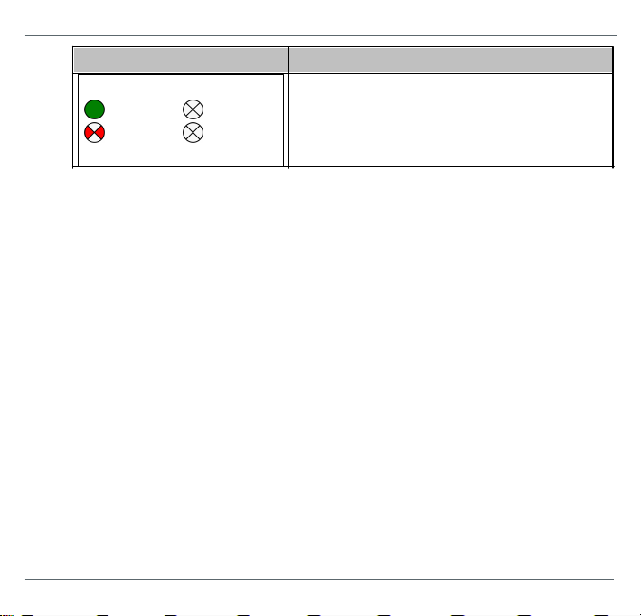
Symbol
Color / frequency
Meaning
green
Visitor address
fla shing sl owly (0.5 Hz)
not in LAS role
fla shing quickly (5 Hz)
LAS role
red
no carrier or H1 l ink is disconnected
fla shing red
no token received
off
H1 link unused
5.4 H1 channel status indicators
The following table shows the channel LEDs and their meaning of al l four channels
(CH1 - CH4):
32 © Softing Industrial Automation GmbH
Page 33

Chapte r 6 - Technical data
Power supply
18 VDC...32 VDC; SELV/PELV supply mandatory
Typical input current is 200 mA; maximum is 1 A (consi dering the
rush-in current at switch-on).
FF-H1
Four FF-H1 channels, compli ant with type 114 of the FF physi cal
layer profile. The Fieldbus voltage range is from 9 VDC...32 VDC.
Preferred value is 24 VDC.
Ethernet
IEEE 802.3 100BASE-TX/10BASE-T
Only ETH 1 is s upported. Do not use ETH 2 (reserved for further us e).
Mini mum ambient
operating
temperature
-40 °C
Storage temperature
-40 °C...+85 °C
Relative humidity
10 %...95 % (non-condensing)
Altitude
Must not exceed 2,000 m
Location
Indoor use only; no direct sunlight
Coating
Conformal Coating based on ANSI/ISA-S71.04 G3
Safety standard
IEC/EN/UL 61010-1 Safety requirements for electrical equipment for
measurement, control and laboratory use - Part 1: General
requirements: IEC/EN/UL 61010-2-201 Sa fety requirements for
electrical equipment for measurement, control and laboratory use Part 2-201: Particular requirements for control equipment (both
with CB scheme).
Ingress protection
IP20
6
Technical data
6.1 Specifications
© Softing Industrial Automation GmbH 33
Page 34

FG-200 HSE/FF Modbu s - Qui ck Startup Gu ide
Minimum distance
Provi de a minimum dis tance of 50 mm to the air inlet and air outlet to ensure
natural convection.
Rotated installation position
The maximum permissi ble ambient temperature values als o apply to a 180°
rotated installation pos ition.
Maximum number
of fieldbus channels
Maximum fieldbus
voltage
Minimum
distance
Maximum permissible
ambient temperature T
a
4
32 VDC
0 mm
55 °C
2
24 VDC
0 mm
60 °C
4
32 VDC
17.5 mm
65 °C
2
24 VDC
17.5 mm
70 °C
6.2 Installation positions
The gateway FG-200 can be mounted horizontally and verticall y. Depending on the
install ation posi tion, different ambient operating temperatures (Ta) are allowed:
Horizontal installation position
34 © Softing Industrial Automation GmbH
Page 35

Vertical installation position
Maximum number of
fieldbus channels
Maximum fieldbus
voltage
Minimum
distance
Maximum permissible
ambient temperature T
a
4
32 VDC
0 mm
40 °C
2
24 VDC
0 mm
50 °C
4
32 VDC
17.5 mm
55 °C
2
24 VDC
17.5 mm
60 °C
Chapte r 6 - Technical data
© Softing Industrial Automation GmbH 35
Page 36

FG-200 HSE/FF Modbu s - Qui ck Startup Gu ide
7
European and International Approval
The equipment meets the following standards:
a) IEC 60079-0:2011 Ed. 6, modified Cor. 2012 + Cor. 2013 / EN 60079-0:2012 + A11:2013
b) IEC 60079-11:2011 Ed. 6 + Corr. 2012 / EN 60079-11:2012
c) IEC 60079-15:2010 Ed. 4 / EN 60079-15:2010
If i ndicated on the device label and in the related documentation, the FG-200 is suitable
for use in gas-Ex atmospheres of Zone 2 in the explosi on groups IIA, IIB and IIC in
temperature cla ss T4, if accommodated in a tested enclosure.
IECEx marking for expl osion protection: Ex nA [ic] IIC T4 Gc.
ATEX marking for explosion protection: II 3G nA [ic] IIC T4 Gc.
The Ex protection method [ic] corresponds only to the FF-H1 fieldbus i nterfaces.
The FG-200 HSE/FF Modbus compli es with the applicable standards and regula tions and
meets the requirements of European Directive 94/9/EC. The requirements for erecting the
device as part of the system in potentially explosive atmospheres (e.g. IEC / EN 60079-14)
must be strictly a dhered.
Certificates
ATEX The EC type examination number for ATEX is: BVS 15 ATEX E 063 X
IECEx The type examination number for IECEx is : IECEx BVS 15.0055X
A copy of the certificate is availabl e in s ection ATEX Type Examination
Certifica te.
The certificate can be downloaded from http://iecex.iec.ch
36 © Softing Industrial Automation GmbH
Page 37

Chapte r 8 - North Ameri can App roval
8
North American Approval
If i ndicated on the device label, the FG-200 i s sui tabl e for use in Cla ss 1, Divi sion 2,
Groups A, B, C and D ha zardous or non-hazardous locations .
The device must be installed in a protective enclosure which meets the requirements for
resi stance to impact and IP54 according to IEC 60529.
Marking for explosion protection: Class I Div.2 Groups A,B,C,D.
Certificate
cULus The cULus l isted Certifi cate of Compli ance number is: 20151215-E356500
See the user manual for a copy of the Certificate of Compliance.
© Softing Industrial Automation GmbH 37
Page 38

FG-200 HSE/FF Modbu s - Qui ck Startup Gu ide
EN 55011
Industri al, sci entific and medical (ISM) devices - radio disturbance
- li mits and methods of measurement
EN 55032
Electromagnetic compatibility of multimedia equipment (MME) and
interference emission
EN 61000-6-4
Electromagnetic compatibility (EMC); Part 6-4: generic standard –
emiss ion for industria l environments
EN 61000-6-2
Electromagnetic compatibility (EMC); Part 6-2: generic standard immunity for i ndustrial environments
Note
To fulfil l the EMC requirements, the other components of your installation
(DC adapter, Industrial Ethernet devices, etc.) als o have to meet the EMC
requirements. A shielded cabl e must be used. In addition, the cable shi eld
must be grounded properly.
CAUTION
This is a Cl ass A product. In a domestic environment this product may cause
radio interference in which case the user may be required to take adequate
measures!
CE
A Declaration of Conformity in compliance with the above standards has
been made and can be requested from Softing Industri al Automation.
9
Declaration of conformity
This device is compliant with EC directive 2014/30/EG for "Electromagnetic Compatibility"
(EMC) and meets the foll owing harmonized standards:
38 © Softing Industrial Automation GmbH
Page 39

Chapte r 9 - De claration of conformi ty
ROHS
This product is ROHS compli ant.
FCC
This equipment has been tested and found to comply with the limits for a
Cla ss A digital device, under part 15 of the FCC Rules. These limits are
designed to provi de reasonable protection against harmful i nterference when
the equipment is operated in a commercial environment. This equipment
generates, uses, and can radiate radio frequency energy and, if not instal led
and used i n accordance with the instruction manual , may cause harmful
interference to radio communications.
VCCI
This Class A product conforms to the regulations of Voluntary Control Council
for Interference (VCCI) by Information Technology Equipment.
WEEE
Electri cal and electroni c equipment must be dis posed of separately from
normal waste at the end of its operational li fetime. Packaging material and
worn components shal l be disposed of accordi ng to the regulations
appli cable in the country of instal lation.
© Softing Industrial Automation GmbH 39
Page 40

Softing Industrial Automation GmbH
Richard-Reitzner-Allee 6
85540 Haar / Germany
http://industrial .softing.com
+ 49 89 45 656-340
+ 49 89 45 656-488
info.idn@softing.com
 Loading...