

Page 1

© Copyright 2014 - 2016 Softing Industrial Automation GmbH
User Manual
Version: MMA-NN-006005-EN-062016-1.30
PROFIBUS Tester 5 (BC-700-PB)
Page 2

The information contained in these instructions corresponds to the technical status at the time of printing of it and is passed on with the
best of our knowledge. The information in these instructions is in no event a basis for warranty claims or contractual agreements
concerning the described products, and may especially not be deemed as warranty concerning the quality and durability pursuant to Sec.
443 German Civil Code. We reserve the right to make any alterations or improvements to these instructions without prior notice. The
actual design of products may deviate from the information contained in the instructions if technical alterations and product improvements
so require.
It may not, in part or in its entirety, be reproduced, copied, or transferred into electronic media.
Disclaimer of liability
Softing Industrial Automation GmbH
Richard-Reitzner-Allee 6
85540 Haar / Germany
http://industrial.softing.com
The latest version of this manual is available in the Softing download area at: http://industrial.softing.com/en/downloads.html
+ 49 89 4 56 56-0
+ 49 89 4 56 56-488
info.automation@softing.com
support.automation@softing.com
Page 3

Copyright 2016 Softing Industrial Automation GmbH 3
Table of Contents
Table of Contents
Chapter 1
.......................................................................................... 7
Introduction
...................................................................................................................... 7
1.1
About the PROFIBUS Tester 5 (BC-700-PB)
...................................................................................................................... 7
1.2
About this document
.................................................................................................................. 7
Purpose 1.2.1
.................................................................................................................. 7
Target group 1.2.2
.................................................................................................................. 8
Conventions used 1.2.3
.................................................................................................................. 9
Document history 1.2.4
...................................................................................................................... 9
1.3
Delivery scope
...................................................................................................................... 10
1.4
Optional accessories
.................................................................................................................. 10
D-sub adapter cable for testing live systems 1.4.1
.................................................................................................................. 11
Adapter Set for M12 Connection Technology 1.4.2
.................................................................................................................. 11
Fieldbus Shield Digital Leakage Current Clamp 1.4.3
.................................................................................................................. 11
Adapter for testing PROFIBUS PA networks 1.4.4
.................................................................................................................. 12
Spare battery 1.4.5
.................................................................................................................. 12
Service interfaces for PROFIBUS DP 1.4.6
.................................................................................................................... 12
Connection Type D-sub
1.4.6.1
.................................................................................................................... 13
Connection Type M12
1.4.6.2
...................................................................................................................... 13
1.5
System requirements
...................................................................................................................... 14
1.6
Connectors and controls
Chapter 2
.......................................................................................... 15
Power up and down the device
...................................................................................................................... 15
2.1
Power-up
...................................................................................................................... 15
2.2
Power-on behaviour without USB connection
...................................................................................................................... 16
2.3
Power-on behaviour when USB connected
...................................................................................................................... 16
2.4
Power-off and sleep mode
Chapter 3
.......................................................................................... 18
Connection to PROFIBUS-DP
...................................................................................................................... 18
3.1
Basics
.................................................................................................................. 18
Note when testing a live bus 3.1.1
.................................................................................................................. 18
Connection types 3.1.2
.................................................................................................................. 18
Adapter cable 3.1.3
.................................................................................................................. 19
Strain relief 3.1.4
.................................................................................................................. 19
Using the security lock port 3.1.5
.................................................................................................................. 19
Test Locations 3.1.6
Page 4

Copyright 2016 Softing Industrial Automation GmbH
Table of Contents
4
...................................................................................................................... 20
3.2
Simple connection for tests during system shutdown
...................................................................................................................... 20
3.3
Connection for testing a live bus (DP)
.................................................................................................................. 21
Connection via D-sub connector with service socket 3.3.1
.................................................................................................................. 22
Direct cable connection 3.3.2
.................................................................................................................. 23
Connection Type M12 3.3.3
...................................................................................................................... 23
3.4
Master simulator, topology scan and cable test
...................................................................................................................... 25
3.5
Connecting to PROFIBUS PA networks
.................................................................................................................. 25
Requirements for analyzing a live bus 3.5.1
.................................................................................................................. 25
PA adapter BC-700-H1 – before you start 3.5.2
.................................................................................................................. 25
Connecting PA-adapter to test device 3.5.3
.................................................................................................................. 26
Bus connection 3.5.4
.................................................................................................................. 27
Test Locations 3.5.5
.................................................................................................................. 28
Analyzing during shutdown 3.5.6
Chapter 4
.......................................................................................... 29
Display and control in stand-alone mode
...................................................................................................................... 29
4.1
Start display
...................................................................................................................... 29
4.2
User interface
...................................................................................................................... 30
4.3
Operating functions and softkeys
...................................................................................................................... 31
4.4
Device status
...................................................................................................................... 32
4.5
Menu functions
...................................................................................................................... 36
4.6
Organize and store test results
Chapter 5
.......................................................................................... 38
Data import into the PC
Chapter 6
.......................................................................................... 39
Device management
...................................................................................................................... 39
6.1
Licenses
.................................................................................................................. 39
Which license is activated? 6.1.1
.................................................................................................................. 39
How to activate a license 6.1.2
...................................................................................................................... 40
6.2
Firmware update
Chapter 7
.......................................................................................... 41
Maintenance and Servicing
Chapter 8
.......................................................................................... 42
Troubleshooting
Chapter 9
.......................................................................................... 44
Tips and tricks for cable testing
...................................................................................................................... 44
9.1
Assessment criteria
...................................................................................................................... 44
9.2
Cable test - fault indications and remedial measures
...................................................................................................................... 47
9.3
Metering the cable segment length correctly
Chapter 10
.......................................................................................... 49
Quality index compatibility between BC-600-PB and BC-700-PB
...................................................................................................................... 49
10.1
What does the quality index indicate and how is the index determined?
...................................................................................................................... 49
10.2
Why might the BC-700-PB display different quality indexes?
Page 5

Copyright 2016 Softing Industrial Automation GmbH 5
Table of Contents
Chapter 11
.......................................................................................... 50
Notes on external trigger input and output
Chapter 12
.......................................................................................... 51
Notes on battery use
...................................................................................................................... 51
12.1
General hints and warnings on rechargeable battery use
...................................................................................................................... 52
12.2
Charge battery
...................................................................................................................... 53
12.3
Replace battery
...................................................................................................................... 53
12.4
Discharge battery
...................................................................................................................... 53
12.5
Storage and transportation
...................................................................................................................... 54
12.6
Battery lifetime
...................................................................................................................... 54
12.7
Battery warranty
...................................................................................................................... 54
12.8
Lithium backup battery
Chapter 13
.......................................................................................... 55
Technical Data
Chapter 14
.......................................................................................... 56
Declarations by the manufacturer
Index ................................................................................................................ 57
Page 6

This page is intentionally left blank.
6 Copyright 2016 Softing Industrial Automation GmbH
Page 7

Chapter 1 - Introduction
Copyright 2016 Softing Industrial Automation GmbH
7
1
Introduction
1.1 About the PROFIBUS Tester 5 (BC-700-PB)
The PROFIBUS Tester 5 (BC-700-PB) is a powerful tool that allows full testing of the bus physics and bus
communication on PROFIBUS DP and PROFIBUS PA segments (option). Using the integrated master
simulator, you can also test the bus physics if the PLC is currently not in operation. In addition you can
check individually check "suspicious" bus stations. The cable test function examines the cabling in
PROFIBUS DP segments. It locates unwanted reflections on the line and verifies proper termination of
cable segments. The tool is powered either by its built-in battery or through an external AC adapter.
The PROFIBUS Tester 5 (BC-700-PB)s the first battery-powered tester, which combines the assessment
of bus physics and bus communication as well as cable testing in one device. It is therefore the only and
truly mobile PROFIBUS diagnostic tool.
1.2 About this document
Read this manual before starting
For damages due to improper connection, implementation or operation Softing refuses any
liability according to our existing guarantee obligations.
CAUTION
Refer also to the safety precautions for battery and battery pack in Section Notes on
battery use .
1.2.1 Purpose
This document describes the BC-700-PB. It provides information about putting into service and also
provides detailed information regarding its safe and correct operation.
1.2.2 Target group
This document is addressed to operating staff which is adept in operating PROFIBUS-systems such as:
Maintenance personnel
Commissioniers
Application engineers and developpers
Trainers
51
Page 8

PROFIBUS Tester 5 (BC-700-PB) - User Manual
8
Copyright 2016 Softing Industrial Automation GmbH
1.2.3 Conventions used
The following conventions are used throughout Softing customer documentation:
Keys, buttons, menu items, commands and
other elements involving user interaction are
set in bold font and menu sequences are
separated by an arrow
Open Start Control Panel
Programs
Buttons from the user interface are enclosed in
brackets and set to bold typeface
Press [Start] to start the application
Coding samples, file extracts and screen output
is set in Courier font type
MaxDlsapAddressSupported=23
Filenames and directories are written in italic
Device description files are located in C:
\<productname>\delivery\software
\Device Description files
CAUTION
CAUTION indicates a potentially hazardous situation which, if not avoided, may result in
minor or moderate injury.
Note
This symbol is used to call attention to notable information that should be followed during
installation, use, or servicing of this device.
Hint
This symbol is used when providing you with helpful user hints.
Page 9

Chapter 1 - Introduction
Copyright 2016 Softing Industrial Automation GmbH
9
1.2.4 Document history
Document version
Modifications compared to previous version
Version 1.00
none - initial publication
Version 1.01
Editorial modifications following internal review
Order numbers for optional accessories added
New device status icons added
New cable test note added
Version 1.10
Revised and enhanced PA-specific topics
Internal battery is installed upon delivery - new section "Replace battery"
inserted.
Added a recommendation with respect to cable shield
Added reference about Softing License Manager
Version 1.11
New optional accessory
Modified battery descriptions
Document structure optimized
Version 1.20
Note regarding providing device serial number when ordering the PA-H1Adapter and activating the license
New section describing how to work with the PA-Adapter BC-700-H1
Version 1.30
New test function Locate Stations
New oscilloscope functionality in stand-alone mode with result display
and without need to use PROFIBUS Diagnostics Suite (requires additional
license, refer to Licenses )
Segments, locations and networks can be created in the PROFIBUS
Diagnostics Suite and then be downloaded to the BC-700-PB (refer also to
the PROFIBUS Diagnostics Suite online help for more information)
1.3 Delivery scope
The BC-700-PB carrying case contains:
Test tool with RS485 interface
Rechargeable battery pack (internal battery)
Wide-range power supply with European and US mains power cables
RS485 D-sub adapter cable BC-600-PB-CB-DSUB-2 “Standard” (cable petrol blue, light connector) for
PROFIBUS DP
USB cable, 2 m
Terminal block for trigger input/output
CD-ROM with driver software, PC software and detailed integrated help system in English and
German
Documentation for BC-700-PB and for the PROFIBUS Diagnostics Suite PC software
33
33
39
33
Page 10

PROFIBUS Tester 5 (BC-700-PB) - User Manual
10
Copyright 2016 Softing Industrial Automation GmbH
Figure 1: BC-700-PB in carrying case
The carrying case comprises cut-outs for optional accessories (leakage current clamp, adapter for
testing PROFIBUS PA networks, spare rechargeable battery)
1.4 Optional accessories
1.4.1 D-sub adapter cable for testing live systems
This D-sub adapter cable is optimized for reduced influence on live PROFIBUS DP segment operation.
Thereby it is most suitable for testing of running plants. The risk of critical influences on bus operation
which can cause a plant standstill is significantly reduced.
Note
Using this cable it is not possible to use both active functions master simulator and topology
detection (see Master simulator and topology scan ).
Figure 2: D-sub adapter cable with reduced influence on bus operation
Softing Order No.: BC-600-PB-CB-DSUB-1
23
Page 11

Chapter 1 - Introduction
Copyright 2016 Softing Industrial Automation GmbH
11
1.4.2 Adapter Set for M12 Connection Technology
Using the M12 adapter set, you can connect the PROFIBUS Tester 5 to field devices with M12
connectors. The set comprises an M12 adapter cable with special pin layout and an M12 terminating
resistor that you can screw on, if required.
Figure 3: Special adapter set for M12
Softing Order No.: BC-600-PB-CB-M12
1.4.3 Fieldbus Shield Digital Leakage Current Clamp
When routing PROFIBUS cables in high-interference environments, electromagnetic interference can
affect the signal quality. By measuring the shield currents with the digital leakage current clamp, you
can locate EMC problem areas and take appropriate countermeasures. The digital leakage current
clamp is supplied in a handy case, including measuring cables. There is also an empty compartment for
the fieldbus shield digital leakage current clamp in the carrying case of the PROFIBUS Tester 5 (BC-700PB).
Figure 4: Fieldbus shield digital leakage current clamp
Softing Order No.: PB-LSZ-CHB3
1.4.4 Adapter for testing PROFIBUS PA networks
The optional plug-in adapter (including test equipment set) for PROFIBUS PA networks enables the BC700-PB to analyze electrical signal quality and data communication in PROFIBUS PA installations. The
BC-700-PB in conjunction with the adapter BC-700-H1 is the proper test tool for identifying basic
installation errors and defective PROFIBUS PA stations.
License for PA option
If you want to use the PA-Adapter BC-700-H1 with your BC-700-PB you need a
corresponding license (upgrade). This license is related to the serial number of your device.
When ordering the PA option we kindly ask you to provide us with the serial number of
your BC-700-PB (see also Licenses) .
Before using the PA adapter
Before using the PA adapter for the first time read carefully section PA-Adapter BC-700-H1
– before you start . Activate the PA license on your device and preform the required
updates.
39
25
Page 12

PROFIBUS Tester 5 (BC-700-PB) - User Manual
12
Copyright 2016 Softing Industrial Automation GmbH
Note
Note the PROFIBUS PA-specific notes in sections Connecting to PROFIBUS PA-networks ,
Display and controls in stand-alone mode and Licenses .
Figure 5: BC-700-H1 adapter
Figure 6: Supplied test equipment set for connecting to PROFIBUS PA segments
Softing order number: DDL-NL-006010 (adapter, license and test equipment)
1.4.5 Spare battery
Intensive use of BC-700-PB during the work day may exhaust the rechargeable battery faster than
expected. In addition charging and discharging will typically wear out the battery pack over the time
(refer to Notes on battery use ). BC-700-PB has an internal energy management. If the measures for
energy saving are not sufficient or are perceived as a disturbance it is recommended operating on the
device in conjunction with an external power supply. Alternatively the user may use a spare
rechargeable battery.
Figure 7: Rechargeable battery pack, Softing Order No.: ABA-NN-006012
1.4.6 Service interfaces for PROFIBUS DP
1.4.6.1
Connection Type D-sub
The D-sub service interface provides a PROFIBUS access point for testing if the existing D-sub
connectors have no service socket or if the bus stations are connected via a terminal block. The service
interface can power the terminating resistor of the D-sub connector. You can thus use it as an active
bus termination at the beginning or end of the bus.
If the PLC allows dropping and adding bus stations on the live bus, you will need this external bus
termination to be able to exchange the first and last bus stations without causing problems on the bus.
The compact unit is rail mounted like a terminal block and powered by an external 24 VDC power
supply. The package includes an 90° angled PROFIBUS connector with a switchable terminating resistor.
25
29 39
51
Page 13

Chapter 1 - Introduction
Copyright 2016 Softing Industrial Automation GmbH
13
Figure 8: D-sub service interface for testing a live bus, Softing Order No.:BC-PBMB-PB-S
1.4.6.2
Connection Type M12
The M12 service interface comprises an IP68 rated T piece, an end cap for the service output of the T
piece, and a 1m PROFIBUS DP cable fitted with a male/female M12 connector on each end.
Figure 9: M12 service interface, Softing order No.: BC-M12DP-PB
1.5 System requirements
Hardware
PC
USB 2.0 Port
operating system
Windows 7, Windows 8, Windows 8.1 and Windows 10 (each in 32 bit and 64 bit version)
Hardware
PC
Page 14
PROFIBUS Tester 5 (BC-700-PB) - User Manual
14
Copyright 2016 Softing Industrial Automation GmbH
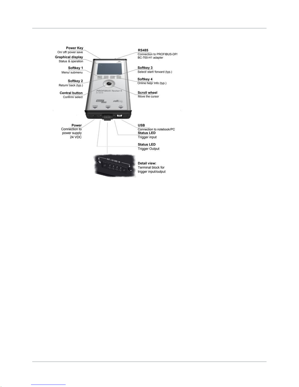
1.6 Connectors and controls
Figure 10: Connectors, buttons and status displays on the BC-700-PB
Page 15

Chapter 2 - Power up and down the device
Copyright 2016 Softing Industrial Automation GmbH
15
2
Power up and down the device
Install PROFIBUS Diagnostics Suite before connecting to a PC
Before connecting the BC-700-PB for the first time with a PC make sure the latest PROFIBUS
Diagnostics Suite and the required drivers are installed on your PC. For detailed installation
instructions refer to the Quick Startup Guide supplied with your PROFIBUS Diagnostics Suite
CD-ROM.
Always connect device directly to an USB port
Use the included USB cable to connect the tool to a PC or notebook. When you use external
USB hubs, notebook docking stations or USB 3.0 ports for connection, problems may occur.
2.1 Power-up
1. Acclimate to room temperature
Before being connected to the AC mains power, the PROFIBUS Tester and the AC adapter must be
acclimated to room temperature to avoid condensation. This may take up to 60 minutes.
2. Power-up
Make sure that you have either connected it to a power supply, or that you have inserted the
battery. Then switch on the tool by pressing the power key at the upper front edge. The display
lights up and self-test starts.
3. Check battery charge level
The display shows the battery charge level indicator ( , , ). If the charge level is too low,
recharge the battery as described in Charge battery .
Hint
We recommend operating the device solely using the wide-range power supply supplied or
using the integrated battery to avoid equalizing currents which can falsify the test results.
The tool is powered by a built-in three cells lithium ion accumulator with 11.1 VDC. Alternatively the
tool can be powered by 24 VDC through the external wide-range power supply.
2.2 Power-on behaviour without USB connection
If not connected to an USB port, the BC-700-PB starts up in stand-alone mode (see Display and controls
in stand-alone mode ) and is immediately ready for testing. During program start-up the splash
screen is shown for a few seconds and displays "USB NOT CONNECTED":
Figure 11: Splash screen – starting without USB connection
31
52
29
Page 16

PROFIBUS Tester 5 (BC-700-PB) - User Manual
16
Copyright 2016 Softing Industrial Automation GmbH
2.3 Power-on behaviour when USB connected
Install drivers before connecting to USB
Install the PC software "PROFIBUS Diagnostics Suite" and the corresponding drivers before
connecting for the first time to a PC or to a notebook. You will find software and drivers on
the PROFIBUS Diagnostics Suite CD-ROM.
The internal battery of BC-700-PB is NOT charged when being connected to a USB port.
On successful completion of the self-test, the BC-700-PB displays:
Figure 12: Power-up display when USB connected
When you start the PROFIBUS Diagnostics Suite control and evaluation software on your computer and
select the PROFIBUS Tester and a network for testing in its user interface, the test tool switches to PC
mode. At this point, a firmware update instead of using the control and evaluation software might be
started automatically. See Firmware update .
The display shows:
Figure 13: Display during test with PC software
Do not connect/disconnect the USB while the device is booting.
2.4 Power-off and sleep mode
Power-down
Press power key for more than three seconds in order to power-down the device. There is no power
consumption if the device is powered down. The device can be stored for long a period of time.
40
Page 17

Chapter 2 - Power up and down the device
Copyright 2016 Softing Industrial Automation GmbH
17
Activate sleep mode
If you want to change manually to sleep mode, shortly actuate the power key. During sleep mode the
BC-700-PB is saving energy and the power key will blink slowly. If a measurement function is currently
active, it is not possible to switch to sleep mode. Depending on the settings in energy management, the
BC-700-PB may automatically change to sleep mode after a predefined period of time.
Return to normal operation mode
You can recover normal operation very quickly by shortly actuating the power key a second time. The
lastly shown menu screen will be displayed which was active before changing to sleep mode.
Automatic power-down
If the BC-700-PB is in sleep mode for more than 2 hours, it will automatically power down.
Page 18

PROFIBUS Tester 5 (BC-700-PB) - User Manual
18
Copyright 2016 Softing Industrial Automation GmbH
3
Connection to PROFIBUS-DP
3.1 Basics
3.1.1 Note when testing a live bus
Test tool side effects
When you connect a test tool, side effects on the system under test are generally
unavoidable. If the PROFIBUS is already disturbed to a certain degree or if Simatic
Diagnostic Repeaters are used, the operation of the PROFIBUS might nevertheless be
affected occasionally. Observe the following connection notes.
3.1.2 Connection types
There are several ways to connect a bus station to a PROFIBUS network:
Using connectors
o D-sub connectors , most of which have an integrated terminating resistor and, optionally, an
additional service socket
o M12 connectors for environments requiring increased IP ratings
o Special vendor-specific hybrid connectors; they are used in combination with special cables to
supply power via the bus
Using terminals for direct connection
Due to the typical daisy-chain topology, the connection points of the bus stations are the only possible
points for connecting the test tool in most cases.
3.1.3 Adapter cable
The BC-700-PB is supplied with the D-sub adapter cable BC600-PB-CB-DSUB-2 Standard (light
connector). For testing on live systems the optional D-sub adapter cable BC-600-PB-CB-DSUB-2 is
recommended. An M12 adapter set is optionally available, see D-sub adapter cable for testing live
systems .
Only use original short cables
Use only the original short cables with special pin layout to connect the unit to a PROFIBUS
network. Do not cascade more than two D-sub connectors with service sockets at the same
time:
Figure 14: Unallowed cascading of D-sub connectors
21
23
10
Page 19

Chapter 3 - Connection to PROFIBUS-DP
Copyright 2016 Softing Industrial Automation GmbH
19
3.1.4 Strain relief
Avoid stress on connectors and bus stations
Avoid stress on connectors and bus stations which might be caused by the device's own
weight.
Possible measures to avoid stress are
support,
strain relief using cable ties or
using a retaining hand strap. Fastening eyes are premounted at the bottom of the tester. You can fix
them either at the bottom or at the top of the tester. The retaining hand strap is not part of the
delivery.
If avoiding stress is not possible, you need to select a different connection point to avoid damage.
3.1.5 Using the security lock port
When using trend logging, the BC-700-PB is typically operated in an unattended manner over a
prolonged period of time. You can connect a Kensington lock to the security lock port to prevent your
device being stolen. The Kensington lock is not part of the product delivery and must be purchased
separately. To use the Kensington lock, refer to the product manual. Tie the Kensington lock cable to a
fixed object and install the other end of the cable to the security lock port.
Figure 15: Using a Kensington lock
3.1.6 Test Locations
Basically you can carry out tests anywhere on a physical PROFIBUS segment using the BC-700-PB. Note
that the use of repeaters creates separate physical segments that each needs to be measured
individually.
For the best and most informative signal quality results, perform the tests at the beginning and end of
each physical segment. If these test results indicate problems that cannot be clearly classified
immediately, you should carry out one or more additional tests at the center.
Page 20

PROFIBUS Tester 5 (BC-700-PB) - User Manual
20
Copyright 2016 Softing Industrial Automation GmbH
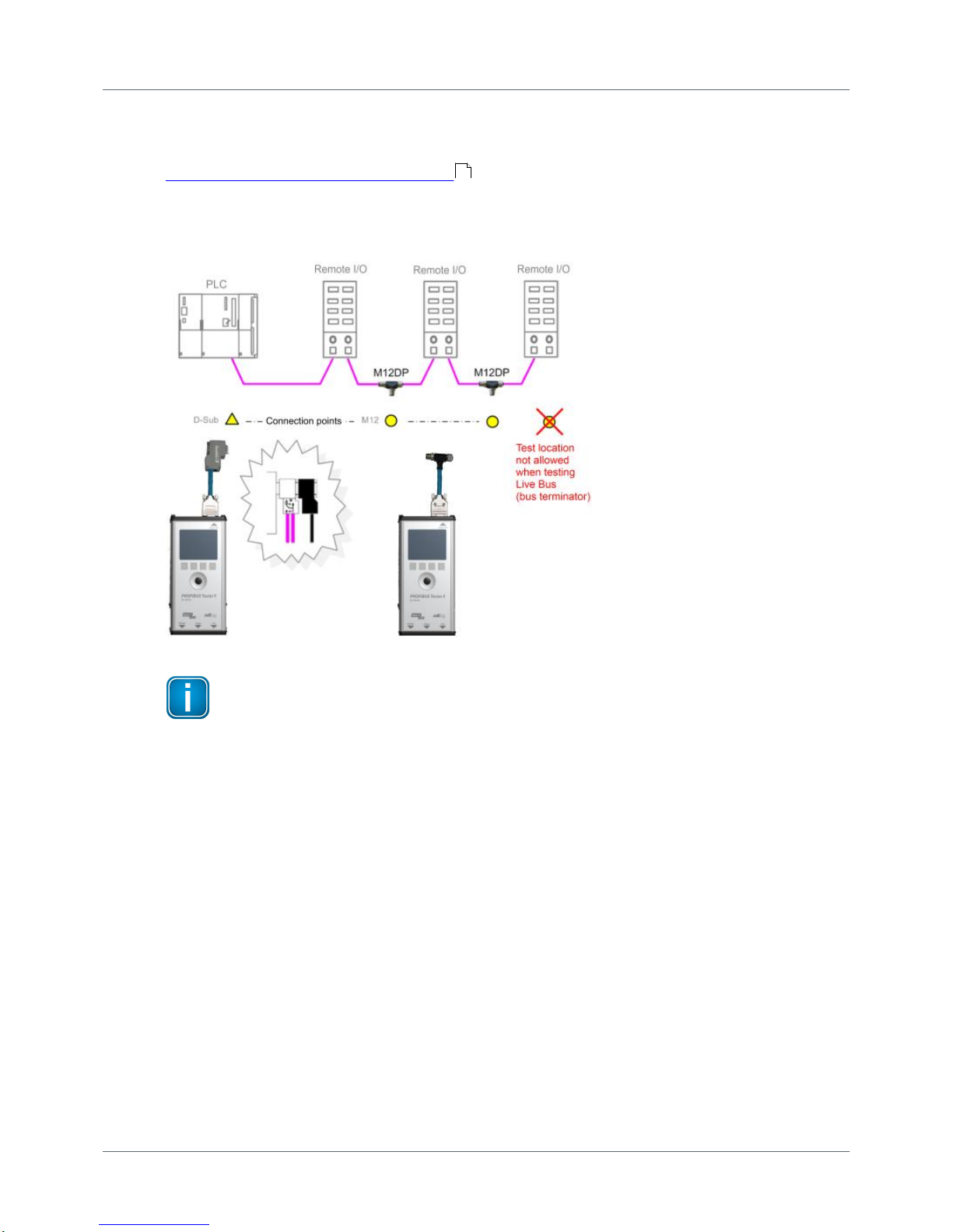
3.2 Simple connection for tests during system shutdown
If all bus stations provide D-sub connectors with an additional service socket, you can simply plug in the
BC-700-PB at that socket. If a D-sub connector does not provide a service socket, you can plug in the
Dsub adapter cable underneath. Keep in mind that you do not cascade more than two D-sub
connectors (see Adapter cable ).
When using M12 connection technology, the M12 adapter cable is looped into the bus. It is essential to
ensure proper termination at the beginning and end of the bus by using the terminating resistor
provided with the M12 adapter set.
Shut down complete installation before connecting
All these simple connection types will divide the bus. You therefore need to shut down the
PLC and all the devices connected to the PROFIBUS; in other words, you need to shut down
the whole installation.
Figure 16: Connection points at system shutdown
3.3 Connection for testing a live bus (DP)
To test a live PROFIBUS with the BC-700-PB during operation, appropriate connection possibilities have
to be provided. If no suitable connection points are available in the existing installation, it is
recommended installing them during system shutdown. This will make future maintenance work much
easier.
Shut down complete installation before connecting
Shut down the PLC and all the devices connected to the PROFIBUS as all these simple
connection types will divide the bus.
18
Page 21

Chapter 3 - Connection to PROFIBUS-DP
Copyright 2016 Softing Industrial Automation GmbH
21
Use D-sub adapter cable BC-600-PB-CB-DSUB-1 for testing on live systems
For testing on live systems we highly recommend using the optional D-sub adapter cable
BC-600-PB-CB-DSUB-1 with reduced influence on bus operation. Refer to D-sub adapter
cable for testing live systems .
3.3.1 Connection via D-sub connector with service socket
If all bus stations provide D-sub connectors with an additional service socket, you can simply plug in the
BC-700-PB at that socket.
Figure 17: Connection points for the D-sub adapter cable
10
Page 22

PROFIBUS Tester 5 (BC-700-PB) - User Manual
22
Copyright 2016 Softing Industrial Automation GmbH
3.3.2 Direct cable connection
To test a live PROFIBUS, you will need additional D-sub service interfaces of the type BC-PBMB-PB-S
(see Service interfaces for PROFIBUS DP ).
Figure 18: Service interfacesprovide connection points at direct cable connection
12
Page 23
Chapter 3 - Connection to PROFIBUS-DP
Copyright 2016 Softing Industrial Automation GmbH
23
3.3.3 Connection Type M12
To test a live PROFIBUS, you will need additional service interface of the type BC-M12DP-PB (see
Adapter set for M12 connection technology ).
Tests on a live PROFIBUS are only allowed on bus segments providing D-sub connection technology.
Only D-sub connectors with service socket can be used as connection points for the test tool. For this
reason, tests can often only be performed at a bus end.
Figure 19: Connection points for the M12 adapter cable
Connect T-fitting between existing cable and 1 meter connection cable
Always connect one end of the T-fitting to the already existing cable and the other end to
the 1 meter connection cable which is supplied with the service interface.
Do not screw the T-fitting of the M12 service interface directly onto a slave.
3.4 Master simulator, topology scan and cable test
Master simulator
The master simulator allows checking the bus cabling and the station addresses during installation and
commissioning, when the PLC (master) is not in operation yet. In addition, you can use this mode to
check individual suspicious bus stations that have been disconnected from the bus.
Topology scan
The topology scan determines the sequence and distances of all passive bus stations (slaves). This
feature requires correct bus cabling, a very good signal quality, and a connection point located directly
at the beginning or end of the bus.
11
Page 24

PROFIBUS Tester 5 (BC-700-PB) - User Manual
24
Copyright 2016 Softing Industrial Automation GmbH
Cable test
The cable test assesses the wiring and can be used to determine a faulty cable location (e.g. short
circuit) by means of reflection test. All three features can only be used during shutdown of the
installation. The D-sub cable BC-600-PB-CB-DSUB-2 which is included in the standard scope of supply
must be used. As long as communication is detected on the bus, i.e. at least one device is an active
master, the functions are disabled. Check If necessary, disconnect every single active device (PLC, MPI
and, if necessary, diagnostic repeaters) from the power supply or the bus. If an active device is at the
end of the bus you want to test, its PROFIBUS connector needs to be unplugged and connected directly
to the PROFIBUS Tester 5 (BC-700-PB). The bus termination in the device connector will then be
powered by the BC-700-PB.
Figure 20: Connection points for topology scan and cable test
Bus stations must only be disconnected from the power supply or the bus during shutdown
of the installation.
The three functions can be started also when the BC-700-PB is disconnected from the bus. If
you then connect the BC-700-PB to a live bus despite the yellow bus status bar indicated by
the PC software, this can cause bus communication problems or a shutdown of the
installation.
Special case: active devices at both ends o the bus during topology scan
On the very rare occasion when there is an active device at each end of the bus, do the following:
1. When using D-sub connection:
a. Additionally switch on the terminating resistor in the D-sub connector of the last slave.
b. Make sure the outgoing cable to the active device at the bus end is connected to the outgoing
connector (marked with "OUT", an outgoing arrow, or "A2/B2").
Page 25

Chapter 3 - Connection to PROFIBUS-DP
Copyright 2016 Softing Industrial Automation GmbH
25
Figure 21: Checking the connection direction at the D-sub connector - topology scan only
2. When using M12 connection:
a. Connect the cable from the bus start or test tool to the incoming M12 connector of the last
slave.
b. A bus termination is required at the outgoing M12 connector of the last slave.
3.5 Connecting to PROFIBUS PA networks
3.5.1 Requirements for analyzing a live bus
When using the BC-700-PB and the BC-700-H1 adapter to carry out measurements on an MBP segment
during operation, it is preferable to connect the tool via free bus connection terminals of the DP/PA
fieldbus coupler. If the bus begins at the coupler, you can simply use the second terminal block at the
DP/PA coupler or at the SK1 or SK2 to sample the bus signal. If the couplers mentioned above are not
located at the beginning of the bus or if the bus begins with an SG3 coupler or if you are interested in
the PROFIBUS PA signal at another test location, we recommend connecting a short spur cable to rail
mounted terminals during system shutdown. This gives you an appropriate connection point and makes
future maintenance work much easier.
3.5.2 PA adapter BC-700-H1 – before you start
Before using the PA adapter BC-700-H1 with the BC-700-PB for the first time make sure the following
preconditions are fulfilled:
PROFIBUS Diagnostics Suite version 3.11 or higher is installed on your PC.
The PA option on the BC-700-PB is activated (refer to Which license is activated?) .
Firmware version on your BC-700-PB is 01.01.02.00 or higher.
3.5.3 Connecting PA-adapter to test device
Mounting
Mount the D-sub connector (male, 9-pin) of the PROFIBUS PA-adapter BC-700-H1 directly to the D-sub
connector (female, 9-pin) of the PROFIBUS Tester 5. If applicable, you may need to remove a mounted
D-sub adapter cable. Optionally you may fix the PA-adapter to the BC-700-PBby means of the two
screws, which are part of the D-sub connector (male, 9-pin). It is possible to stow the BC-700PBtogether with the mounted PA-adapter in the carrying case after use.
Disassembly
Disassemble the PA adapter as described above but in reverse order.
Please note also the PROFIBUS PA-specific information in section Display and controls in stand-alone
mode .
39
29
Page 26

PROFIBUS Tester 5 (BC-700-PB) - User Manual
26
Copyright 2016 Softing Industrial Automation GmbH
Stop running tests prior to mounting or disassembling the PA-adapter
To prevent loss of test data and in terms of a structured mode of operation you should
solely mount or disassemble the PROFIBUS PA-adapter BC-700-H1 when there is no running
test function.
Two light emitting diodes directly give a check-back indication with respect to the operational state of
the PA-adapter and to the DC voltage (supply voltage), see figure.
Figure 22: Connecting PA-adapter to test device
3.5.4 Bus connection
The supplied test equipment set allows to easily connect the BC-700-H1 adapter to the PROFIBUS PA
segment. Alternatively you can use a short length of PROFIBUS PA standard cable to connect the tool to
the bus.
In general it is sufficient to use PA+ and PA-
Protocol analysis, testing DC voltage level (supply voltage) and AC signal levels (MPB peakpeak voltage) require only a proper connection to signal wires PA+ and PA-. To guard
against and prevent errors in test and parasitic coupling (EMC) it is additionally
recommended using cable shielding or interconnecting the shield connector.
Figure 23: PROFIBUS-PA pin assignment
Do not use in hazardous areas
The BC-700-PB and BC-700-H1 adapter must not be used in hazardous areas and must not
be connected to an intrinsically safe MBP-IS segment (blue terminals of fieldbus coupler; in
some cases blue bus cables).
Page 27

Chapter 3 - Connection to PROFIBUS-DP
Copyright 2016 Softing Industrial Automation GmbH
27
3.5.5 Test Locations
There are several ways to connect bus stations to PROFIBUS PA:
Using terminals for direct connection
Using M12 connectors in the field (unfortunately there is no rule defining on which sides the male
and female connectors are to be used)
Field distributors and T pieces are widely used. As opposed to PROFIBUS DP, spur cables are allowed to
a limited extent for PROFIBUS PA.
The following types of DP/PA fieldbus couplers are the most common:
Simatic DP/PA couplers from Siemens, also as part of DP/PA links
SK1, SK2 and SK3 segment couplers, e.g. from Pepperl+Fuchs (or sometimes under a different label)
Irrespective of the connection types used for the field devices, the fieldbus couplers are usually
installed in a control cabinet, and the PA output is connected there via terminals.
Connection to MBP-IS is not allowed.
You can use the connection points of bus stations or access points inside the field distributors as
connection points. Establishing the electrical connections required for measuring may vary from system
to system and might not be possible during operation.
Figure 24: Connection points for PROFIBUS PA
Hint
An appropriate connection point is located directly at the DP/PA coupler. At this point, the
tool can continue to analyze the bus communication even when lines are interrupted. The
measurements are not affected by repeaters or field barriers.
Page 28

PROFIBUS Tester 5 (BC-700-PB) - User Manual
28
Copyright 2016 Softing Industrial Automation GmbH
3.5.6 Analyzing during shutdown
If there is no possibility for connection, you need to improvise in order to pick up the bus signal at an
existing terminal block of the fieldbus coupler, the field distributor, segment protector or a field device.
For example, you can try a double assignment of bus terminals.
Shut down the system before you divide the bus.
Disconnect all bus stations from the power supply.
Page 29

Chapter 4 - Display and control in stand-alone mode
Copyright 2016 Softing Industrial Automation GmbH
29
4
Display and control in stand-alone mode
The BC-700-PB always starts in stand-alone mode unless it is USB connected to a PC or notebook. The
readings are shown on the graphical display. You can control the tool with the four softkeys, the scroll
wheel and the push button in center of the scroll wheel (see Connectors and controls ).
When you establish a USB connection during stand-alone mode while a test is running, the test will be
aborted and the tool will be reset (restart). The display briefly shows: "Switching to PC mode".
4.1 Start display
The start display appears after start-up in stand-alone mode (or when all dialogs or functions have been
stopped and you have been returned to the main menu). The start display (with main menu) is your
starting point where you can open any of the test functions or additional administrative functions.
Figure 25: Start display
4.2 User interface
The user interface of BC-700-PB comprises four parts:
Device Status
The device status in the upper right corner provides information such as the battery charge level
indicator, system load status, memory information, state of master simulator, connected interfaces
and adapters,…
Application status
The application status at the upper edge on the left displays which function or sub-function is
currently selected.
Workspace
The Workspace in the center of the graphical user interface contains the start page, detail views for
the bus analyzes and views for administrative purposes. At a glance the user views the most
important information with respect to the selected test function.
Control information
Control information is shown at the lower edge of the user interface. The meaning of the four
softkeys is explained in Operating functions .
14
30
Page 30

PROFIBUS Tester 5 (BC-700-PB) - User Manual
30
Copyright 2016 Softing Industrial Automation GmbH
Figure 26: Division of screen areas
The presentation of dialog information uses four layouts:
Additional information which is typically less important is shown on user request in Info-dialogs.
Access to this read-only function or information is subjected to a sub-menu function or to the
[Info]-softkey.
Other functions may require appropriate user input by means of input dialogs. The colors light blue
and blue indicate, which elements are selectable or changeable by means of the input focus
(cursor).
Error messages are displayed in error dialogs.
The BC-700-PB provides a context-sensitive online help. Their content is shown in quick reference
dialogs using a smaller font size.
Figure 27: User interface dialogs
4.3 Operating functions and softkeys
Use the scroll wheel, in order to move the cursor within lists, tables, dialogs and alphabetic strings.
Selected elements are highlighted in blue. Press the central button of the scroll wheel or press the
Selection- or [Info]-softkey in order to call functions or to request additional information. The
appearance of controls will change in a context-sensitive manner. If a softkey is grayed out, the
corresponding operating function is disabled.
Page 31

Chapter 4 - Display and control in stand-alone mode
Copyright 2016 Softing Industrial Automation GmbH
31
Icon
Function
Open menu/ submenu
Browse backwards, quit menu function
Browse tab to the left
Browse tab to the right
Confirm/ select (central button in scroll wheel)
Start a previously stopped function
Stop a running function
Request details for selected elements (press briefly) or
Open context-sensitive reference (press button approx. for 2 seconds)
Open context-sensitive reference
4.4 Device status
The following table contains the meaning of the device status icons. Device status information is
available and visible at any time of device operation in stand-alone mode.
Battery charge level (internal battery with/without AC adapter connected)
Icon
Description
, ,
Internal battery charge level (approx. 100 %, 66 %, 33 %)
Critical battery charge level. BC-700-PB is going to shut down
automatically in a couple of minutes. Connect BC-700-PB to the AC
adapter.
AC adapter connected and battery is charging
Battery completely charged - without AC adapter connected
Battery completely charged - with AC adapter connected
Battery not found or defective. The device runs with external power
supply.
Page 32

PROFIBUS Tester 5 (BC-700-PB) - User Manual
32
Copyright 2016 Softing Industrial Automation GmbH
Testing and measurement status
Icon
Description
PROFIBUS DP:
There is bus activity. If the LED is green, but no baud rate is displayed (e.g. in
Bus Status function), the bus activity results from disturbances and not from
regular frames.
PROFIBUS PA:
There is bus activity (31.25 kbit/s) and the DC voltage level (fieldbus supply
voltage) is clearly keeping the limit values.
PROFIBUS DP:
No bus activity, open circuit voltage within correct range between 0.8 V and
1.4 V. The bus termination is correct, but no frames are transmitted on the
bus. To run a test, you have to either switch on the PROFIBUS master or
activate the master simulator.
PROFIBUS PA:
Either there is no activity on the bus or the DC voltage level is below the
adjustable critical limit. Use the Bus Status function in order get more details
about bus communication and DC voltage level.
PROFIBUS DP:
No bus activity, open circuit voltage below 0.8 V or above 1.4 V. If an open
circuit voltage greater than 0 V is displayed in Bus Status function, the bus has
not been properly terminated. An open circuit voltage of about 0.5 V to 0.6 V
indicates that no power is supplied to one of the two bus terminations.
PROFIBUS PA:
The DC voltage level is either below the fixed error limit of 9 V or above the
maximum allowable fixed error limit of 32 V. Use the Bus Status function in
order get more details about bus communication and DC voltage level.
Master simulator is active. You can start the master simulator from the "Extras
> Master simulator" menu.
The BC-700-PB has detected the mounted PA-adapter BC-700-H1 and the
license "PA Test" has been appropriately activated on the PROFIBUS Tester.
The test system is ready to operate for testing PROFIBUS PA networks.
4.5 Menu functions
The following table gives a brief overview about the menu functions of BC-700-PB in stand-alone mode.
The device help contains a more detailed description of operating functions (use the [ ] softkey in the
corresponding context).
The operating philosophy and the user interface for analyzing PROFIBUS DP- and PROFIBUS PAnetworks are identical and thus, eliminating the need to learn the operating philosophy of an additional
device. The PA-specific information will be explained in [square brackets in italic type].
Page 33

Chapter 4 - Display and control in stand-alone mode
Copyright 2016 Softing Industrial Automation GmbH
33
Main menu
Submenu(s)
(> Submenu function)
Short description
Test functions
Bus status
> Overview
Bus Status function (Overview) assesses bus physics and
bus communication and displays the test result in a
simplified view.
Bus status
> Detail view
Bus Status function (Overview) assesses bus physics and
bus communication and displays the test result in a
simplified view.
Signal quality
[PA: Signal Level]
The signal quality [PA: signal level] test determines the
signal quality index [PA: signal level] for each bus
station and displays the test result in a bar diagram. The
test location is particularly important when you are
testing the signal quality [PA: signal level].
Additional information is available such as
PROFIBUS DP: Signal/ Noise ratio, rise time and
numerical values with respect to signal quality testing.
PROFIBUS PA: Deviation of bitrate, signal polarity and
numerical values with respect to signal level testing.
Signal quality
[PA: Signal Level]
> Select test location
The test location is particularly important when you are
testing the signal quality [PA: signal level]. We
recommend performing at least two signal quality [PA:
signal level] tests per physical segment (at both ends of
the corresponding segment).
Signal quality
[PA: Signal Level]
> Settings evaluation
The signal quality evaluation settings contain limit
values for
PROFIBUS DP: quality index, signal-to-noise ratio, rise
time and timeout.
PROFIBUS PA: DC voltage level and AC signal level
Locate Stations
> Select test location
Detects the topological order of the stations on the bus
line by measuring the distances between masters and
their related slaves. The measurement is purely passive
and does not disturb a running system.
Locate Stations
> Delete location data
Allows to delete data from test locations.
Oscilloscope
Using the Oscilloscope dialog you can analyze the
waveform on the PROFIBUS cable.
Page 34

PROFIBUS Tester 5 (BC-700-PB) - User Manual
34
Copyright 2016 Softing Industrial Automation GmbH
Main menu
Submenu(s)
(> Submenu function)
Short description
Cable test
[PA: not available]
The cable test functionality examines the cabling in
PROFIBUS segments. It detects the cable segment
length, scans for unwanted reflections on the line and
verifies proper termination of the cable. In case of a
fault you will get an error description and a distance
indication (if possible) for troubleshooting actions. You
can only perform a cable test starting at one end of a
PROFIBUS line; during the test no active stations
(Master, MPI panel, ...) must be connected to the
related cable segment.
For further information and starting points in order to
correctly interpret the fault indication see List of fault
indications and remedial measures .
Cable test
[PA: not available]
> Edit Configuration
In the context of cable testing we recommend providing
additional information about the corresponding cable
segment (physical segment); this is important for
proper detection of line length, compliance with
maximum allowed segment length as well as for proper
documentation of test results. Give full particulars with
respect to the configuration of each cable segment.
Cable test
[PA: not available]
> Cable Segment List
The cable segment list shows all segments which belong
to the currently selected network in a tabular overview;
an OK- or error-message is displayed (if available).
Particularly in the context of acceptance control the
commissioner can get a survey over the cabling of the
network.
Recording
Functions
Quick Test
[PA: not available]
The Quick Test allows full testing of bus physics and bus
communication. The test data is stored in the currently
selected net (see submenu "Network Management")
and can be imported by the PROFIBUS Diagnostics Suite
software application.
A progress label is displayed during the quick test. After
completion of the test, a tabular overview is displayed
which informs you about existing and missing quick
tests respectively.
44
Page 35

Chapter 4 - Display and control in stand-alone mode
Copyright 2016 Softing Industrial Automation GmbH
35
Main menu
Submenu(s)
(> Submenu function)
Short description
Trend
[PA: not available]
Trend logging is used for detecting rare or sporadic
faults over a prolonged period of time. The function
monitors both the bus physics and critical events in the
bus communication. The test data is stored in the tool
and can be imported by the PROFIBUS Diagnostics Suite
software application. The tool displays the duration of
the running trend test.
After completion of the test, a tabular overview is
displayed which informs you about existing and missing
quick tests respectively. The Trend Test runs until it is
manually stopped, ends when the power supply is
interrupted or when the maximum logging time of 99
hours and 59 minutes is reached.
Network
Management
You can easily create networks, segments and test locations in
PROFIBUS Diagnostics Suite and then load this data onto your
test tool. For more information refer to the onlinehelp of
PROFIBUS Diagnostics Suite in section "Prepare stand-alone
tests".
Networks
Select network - The test tool stores the test results
that are associated with a real PROFIBUS network in a
separate file folder for that network. Three configurable
directories are available. The radio button shows which
network is currently selected.
Each network contains at least one physical segment
and test location.
Networks
> Edit Network
Segment list - The signals of stations located behind a
repeater are regenerated and transmitted by the
repeater. Therefore, all stations behind the same
repeater will have identical test results. When using
repeaters, you will thus have to test each segment
separately.
One test location belongs exclusively to one segment.
Networks > Segment List
> Edit Segment
Assign test locations to segments: Those test locations
are particularly important which are located within the
currently tested physical segment. We recommend
performing at least two signal quality tests per physical
segment (at both ends of the corresponding segment).
Test Locations
Manage test locations: Particularly when testing signal
quality, the test location has a major influence on the
test result.
To find these faults, it is recommended to measure the
signal quality at different locations on the bus, at least
at both line ends. If a PROFIBUS network comprises
multiple segments connected through repeaters, you
have to measure each segment separately.
Page 36

PROFIBUS Tester 5 (BC-700-PB) - User Manual
36
Copyright 2016 Softing Industrial Automation GmbH
Main menu
Submenu(s)
(> Submenu function)
Short description
Extras
Master simulator
[PA: not available]
Using the master simulator, you can even test the signal
quality while you are still setting up a PROFIBUS
installation and the actual master (controller) is not
operational yet.
The master simulator is disabled by default when you
switch on the tool. You can only select a baud rate on
the display and thus start the master simulator if no
other master is active.
If you use the master simulator in a trend test, quick
test recording or when running the Bus Status function,
the values for the critical events will not be informative
because the master simulator does not execute a
regular DP protocol.
Settings
Energy Management
The energy management settings have a considerable
bearing on battery life of the test device with respect to
one battery charge. We recommend activating the
automatic profile "economy".
Language
Select language
Hardware Information
Hardware information is displayed here (version- and
serial numbers).
License
Displays license information
4.6 Organize and store test results
BC-700-PB comprises three predefined network folders: a default network folder and two empty
folders.
A network folder is a directory containing all the test results assigned to a network. The name of the
network folder is the same as the network name displayed during the data import into the PC.
The default network is provided for spontaneous tests and is a fixed component of the project
management and cannot be deleted. However, you can rename and edit the default network and start
testing using this network. If you are deleting all networks, automatically the default network including
a default segment and a default test location will be generated in the network folder.
A network in BC-700-PB comprises one or more segments, and one or more test locations. A minimum
network configuration (default network) comprises one segment (default segment) and one test
location (default test location).
The test location has a major influence on the test result, particularly when testing signal quality, using
the oscilloscope function or using the cable test function. To store all test results within a network in
the BC-700-PB, you have to set the radio button to the corresponding network in the networks function
(see also User interface ).
29
Page 37
Chapter 4 - Display and control in stand-alone mode
Copyright 2016 Softing Industrial Automation GmbH
37
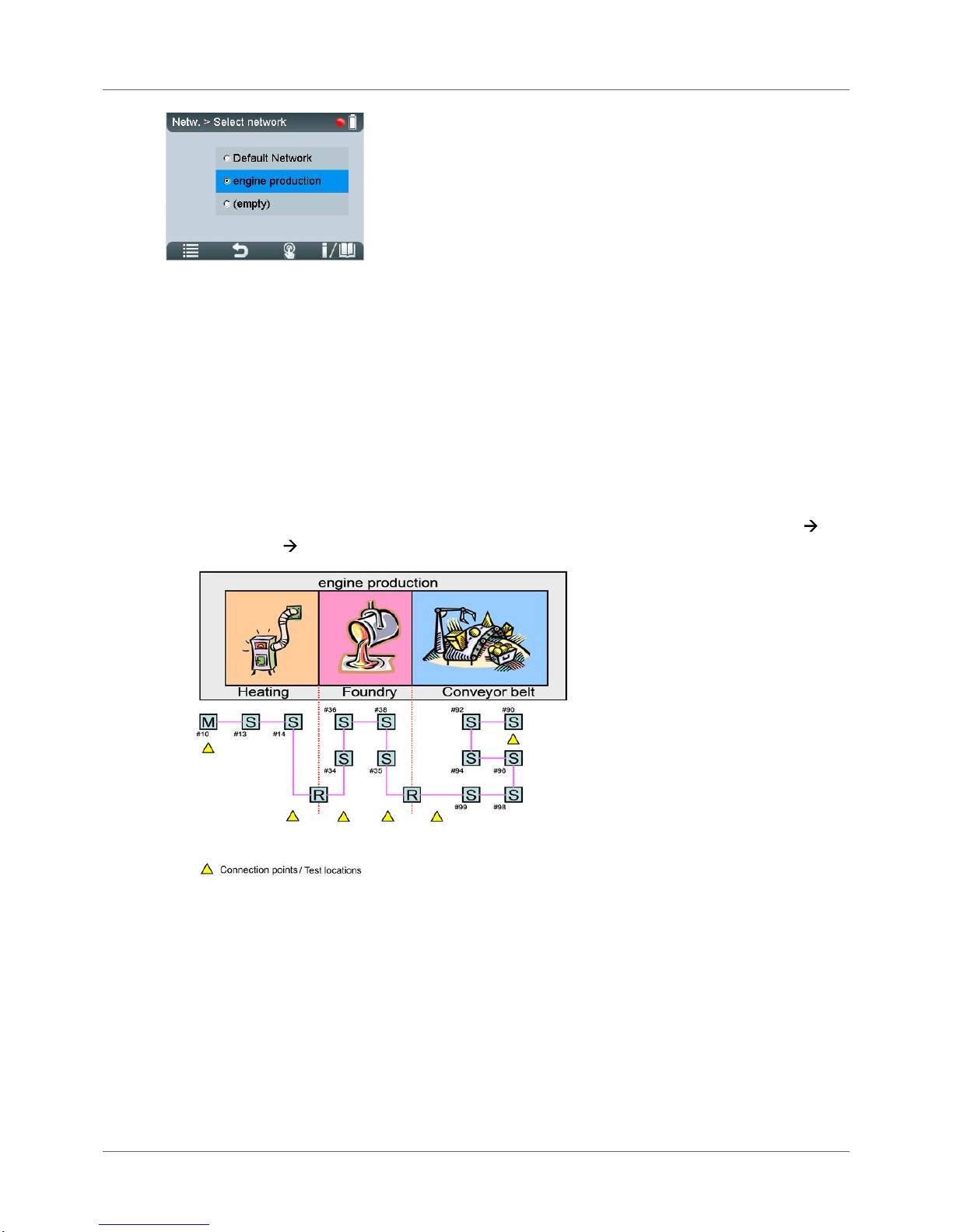
Figure 28: Select Network – the radio button is set to "engine production"
Test results in stand-alone mode are stored under the specified test location in the network you have
defined as the storage location. Thus, test results will be organized and stored in BC-700-PB according
to their test location. Refer to the figure below to see an example network which could be organized as
follows in BC-700-PB (recommendation):
1. Use the Networks/ Select network function and select an empty network folder. Enter the network
name (e.g. "engine production").
2. Use the Edit network function and rename the default segment (e.g. to "heating") and add two new
segments (e.g. "foundry" and "conveyor belt").
3. Use the Test locations function and generate six test locations.
4. Assign test location to segments. To do so, use the Test locations function or select Networks
Edit Networks Edit Segment.
Page 38

PROFIBUS Tester 5 (BC-700-PB) - User Manual
38
Copyright 2016 Softing Industrial Automation GmbH
5
Data import into the PC
You can import quick tests, trend logs and cable test results from the test tool into the PC software.
Proceed as follows:
1. Start the PROFIBUS Diagnostics Suite.
2. Connect the PROFIBUS Tester 5 (BC-700-PB). An additional Import Test Data dialog box appears
automatically showing the test data previously saved:
Figure 29: Importing test data
3. The Import test data dialog box has been filled in advance and contains already the network
designations, segment designations and the test location designations, which have been derived
from the network management of BC-700-PB.
4. For ALL the stored data, you need to fully select the action to be performed, the network/project
and the test location to which you want to store the data. The default action "Import and Delete"
deletes the test data in the tool after the import is completed. This frees the allocated memory
locations for new tests.
The imported Quick Tests and Trend logs are fully compatible with the test data that can be acquired
using the PC software.
Page 39

Chapter 6 - Device management
Copyright 2016 Softing Industrial Automation GmbH
39
6
Device management
6.1 Licenses
Some test functions of the BC-700-PB require activating a license.
Licenses are related to the serial number of your device and can only be used together with
this device. Please include the serial number of your device when ordering a license.
If you already have licensed an option and you want to purchase an additional license
please send your license key to Softing. This key contains both, the serial number and the
license(s) already bought.
You can read the license key that is currently being used by the device from the License
Manager (see How to activate a license ). To do so select Softing Interface, the select tab
Interface Licenses. The connected device together with its serial number and its license key
is displayed. Copy the license key with a right mouse click and then insert it into a
document.
6.1.1 Which license is activated?
Activated licenses are displayed in the BC-700-PB in menu Settings License.
Disabled functions or functions without a license will be grayed out or are not visible in the main menu
in stand-alone mode.
Hint
When USB is connected you can view the license activation status in PC-software PROFIBUS
Diagnose Suite (Help Hardware Info).
6.1.2 How to activate a license
I. Install the PROFIBUS Diagnostics Suite (from your delivery CD-ROM or from the Softing download
area in http://industrial.softing.com/en/downloads.html).
II. Perform a firmware update:
1. Connect the BC-700-PB with the USB cable to the PC and power on the test tool.
2. Start the PROFIBUS Diagnostics Suite. The software verifies whether the firmware needs to be
updated. If your firmware needs to be updated, a firmware update window appears. Click
[Automatic Update], to update the firmware.
3. Close the PROFIBUS Diagnostics Suite after a successful firmware update.
III. Activate your license in BC-700-PB:
39
Page 40

PROFIBUS Tester 5 (BC-700-PB) - User Manual
40
Copyright 2016 Softing Industrial Automation GmbH
1. Connect the BC-700-PB with the USB cable to the PC and power on the test tool.
2. Start the License Manager with Start All Programs Softing License Manager License
Manager V4.
3. <t0/>The Softing Interface button in the left area must be activated<t6/>. If it is deactivated,
click the reload arrow ( ) in the upper right corner.
4. Click the Softing Interface button. Then select tab Interface Licenses. the BC-700-PB and its
serial number are displayed.
5. Enter the license key from the supplied certificate into the field License Key.
6. Click [Enable license]. The license acquired s now displayed in the information area.
7. Close the Softing License Manager.
6.2 Firmware update
Firmware updates are made available as required. They are provided with the updates to the PC
software on our website download area (http://industrial.softing.com/en/downloads.html) They allow
access to new or improved functionality (see also how to activate a license or User Manual
"PROFIBUS Diagnostics Suite - first steps".
39
Page 41

Chapter 7 - Maintenance and Servicing
Copyright 2016 Softing Industrial Automation GmbH
41
7
Maintenance and Servicing
The BC-700-PB is maintenance-free and does not require calibration. We recommend excluding this
device from control of measuring and monitoring of devices. Repairs may only be carried out by the
device manufacturer. All returns must be made without supplied carrying case and accessories (unless
otherwise agreed). Please also include a brief fault description and a phone number at which we can
contact you should we need further details. Please also include a brief fault description and a phone
number at which we can contact you should we need further details. In case of returns within the
warranty period, please also enclose a copy of the invoice or delivery note.
The built-in battery is subjected to normal wear and tear. The battery capacity decreases in the course
of years; this is typical for specified normal operation. Exhaustive discharge and overcharge or
exhaustive operation of the device in conjunction with very high or low temperatures will accelerate
the battery aging process (refer to Notes on battery use) .
51
Page 42

PROFIBUS Tester 5 (BC-700-PB) - User Manual
42
Copyright 2016 Softing Industrial Automation GmbH
8
Troubleshooting
Problem
Possible causes and remedies
The display of the BC700-PB remains blank.
Possible cause:
The BC-700-PB always needs an additional external power
supply or the internal battery is not installed.
Remedy:
Use the supplied external AC adapter to connect the tool to the
mains power supply.
Charge the built-in battery
Alternative cause:
The tool is defective.
The rechargeable battery is defective.
Remedy:
Return the tool to the manufacturer.
Replace the rechargeable battery.
The display shows the
error message "USB
ERROR - Refer to manual
or disconn. for standalone mode".
Possible cause:
This error message can be caused by poor physical connection
via USB (loose contact).
Remedy:
Check the USB cable and connector.
Alternative cause:
The device may be connected via external USB hub, notebook
docking stations or USB 3.0 port which could evoke problems
during driver installation.
Remedy:
We recommend connecting the unit directly to a USB 2.0 port.
The baud rate is not
detected automatically
on a live PROFIBUS.
Possible cause:
Massive disturbances in the bus physics.
Remedy:
Manually set the baud rate and repeat the test.
A main menu function is
grayed out or is not
visible respectively
Possible cause:
Missing license.
Outdated firmware version in use.
Remedy:
Please check your bill of delivery if the license is included in
your order.
Please download the latest firmware version.
It is not possible to
activate the sleep mode
for energy saving
Possible cause:
A test function is currently active.
Remedy:
Page 43

Chapter 8 - Troubleshooting
Copyright 2016 Softing Industrial Automation GmbH
43
Problem
Possible causes and remedies
Stop running test functions before activating the sleep mode.
After some minutes the
display becomes dark
Possible cause:
Backlight was switched off automatically in the context of energy
saving settings.
Remedy:
Press any push button or push the scroll wheel.
Alternative cause:
The tool automatically entered the sleep mode/ powered off in
the context of energy saving settings.
Remedy:
Press the power key in order to power up the device.
The device is running but
does not react to any
user input
Possible cause:
The program has crashed.
Remedy:
Press the power key for at least three seconds to turn off the
device.
Interrupt the power supply. You may need to open head screws
on the back of the device and remove the connecting plug of the
rechargeable battery.
After switching on the
device, the splash screen
persists and shows
"Selftest failed! System
halted"
Possible cause:
Self-testing has identified faulty device components.
Remedy:
Return the tool to the manufacturer.
Optional: Press the key combination [Softkey 1] + [Softkey 4]
during switch-on of the device. Detailed information about selftesting is shown.
You can find support contact data on the cover sheet's back side of this document.
Page 44

PROFIBUS Tester 5 (BC-700-PB) - User Manual
44
Copyright 2016 Softing Industrial Automation GmbH
9
Tips and tricks for cable testing
Perform cable test in stand-alone mode without mains adapter connected
When using the cable test function we recommend removing the mains adapter and
operating on the BC-700-PB by means of the built-in battery in stand-alone operation
mode.
9.1 Assessment criteria
The cable test function examines the cabling in PROFIBUS DP segments and summarizes the test result
in a single statement ("Ok" or "Error"). Amongst technical criteria with respect to the cabling the overall
assessment incorporates additional criteria with respect to the workflow and to plant planning. Under
certain conditions a user may not be able to successfully finish cable testing in a dedicated segment
(e.g. at a very early installation phase of a facility, when there is no possibility to power the bus
terminators). In such a case it is recommended adding a comment to the corresponding test report
which clarifies the circumstances that lead to the negative cable test result. Not all errors will inevitably
lead to downtimes or represent under the specific circumstances a severe error. At last, the
commissioner or maintenance personnel decides, if a PROFIBUS-network is functioning properly or
notl. The corresponding person gets necessary information and recommendations by means of using
appropriate PROFIBUS diagnostic tools. The table below contains assessment criteria which must be
fulfilled in order to successfully complete the cable testing function.
Failed, if at least one of the following criteria is
fulfilled
Passed, if all of the following criteria are fulfilled
Substatial troubleshooting effort was carried out
unsuccessfully and there are still errors on the
cabling
All cabling errors have been successfully
eliminated
The corresponding PROFIBUS DP segment is still
affected by reflections on the cable
The corresponding PROFIBUS DP cable segment is
free of reflections
The user did not run through the tree steps of
cable testing
The user has run through each of the three steps
of cable testing successfully
Detection of the cable segment length fails
The cable segment length has been successfully
detected
Bus termination is not as expected
The terminators at both ends of the cable
segment are switched on and properly powered
The detected cable segment length exceeds the
limit value specified by PI (PROFIBUS PROFINET
International)
The baudrate (entered by user) and the detected
cable segment length fit together according to PI
recommendation (PROFIBUS PROFINET
International)
9.2 Cable test - fault indications and remedial measures
The classifying text messages in the graphical user interface of BC-700-PB which describe the cabling
errors are kept concisely. The table below lists possible cabling error messages and provides a detailed
description of the discovered fault indications. The column on the right contains "remedial measures"
and further starting points in order to correctly interpret and to repair the indicated fault.
Page 45

Chapter 9 - Tips and tricks for cable testing
Copyright 2016 Softing Industrial Automation GmbH
45
The BC-700-PB uses amongst other methods impulse reflectometry for assessing the cabling and
classifying and locating errors on the cable. Multiple cable errors, which exist simultaneously on the
cable may result in an imprecise cable test result. The more the corrective repair of the cable is
proceeding, the more precise the cable test results in the corresponding PROFIBUS cable segment will
be.
Electromagnetic interferences may influence PROFIBUS cable testing in a negative manner because
cable conductors may act like an antenna. Consider this aspect during cable testing and take care of
proper functional earthing of your plant respectively. Existing high frequency noise voltage may
negatively influence the BC-700-PB if operated by means of the external power supply. We recommend
operating on the BC-700-PB by means of the built-in battery under the above mentioned prevailing
conditions.
Cable testing error message
displayed on BC-700-PB
Remedial measures - starting points for correctly interpreting and
repairing the indicated fault
Break on line A
The green signal line of the PROFIBUS-cable is broken. Search for
damage on the cable in the vicinity of the indicated error location.
Fatigue breakage or a faultily assembled PROFIBUS-connector may
cause this error. The green signal line typically is connected to Pin 8 of
the PROFIBUS Sub-D type connector.
Break on line B
The red signal line of the PROFIBUS-cable is broken. Search for damage
on the cable in the vicinity of the indicated error location. Fatigue
breakage or a faultily assembled PROFIBUS-connector may cause this
error. The red signal line typically is connected to Pin 3 of the
PROFIBUS Sub-D type connector.
Break on shield
The shielding conductor is broken in the tested cable segment.
Alternatively electromagnetic shielding is not applied for in a
continuous manner. Search for damage on the cable in the vicinity of
the indicated error location. Fatigue breakage or a faultily assembled
PROFIBUS-connector may cause this error.
In rare cases electromagnetic shielding may be disrupted intentionally
in order to avoid electromagnetic interferences. Check this issue with
the planning personnel of the PROFIBUS-facility.
Short circuit between A and B
There is an unusual low ohmic or capacitive resistance between signal
lines A and B. Search for damage on the cable in the vicinity of the
indicated error location. A severe crush of the cable or multiple
unpowered bus terminators may cause this error.
In addition search for illegal spur lines and check, if moisture
penetrated the cabling or if the cabling is heavily soiled.
Short circuit between A and
shield
Short circuit between B and
shield
Short circuit between A, B
and shield
There is an unusual low ohmic or capacitive resistance between the
mentioned signal lines and conductors. Search for damage on the cable
in the vicinity of the indicated error location. A severe crush of the
cable or a faultily assembled PROFIBUS-connector may cause this
error.
In addition search for illegal spur lines and check, if moisture
penetrated the cabling or if the cabling is heavily soiled.
Capacitive Load / Spur Line
There is an unusual capacitive load between signal lines A and B and
the shield conductor. An illegal spur line or interference-suppression
capacitors may cause this error. This is common usage with "overcompensated" or defective PROFIBUS-devices.
Page 46

PROFIBUS Tester 5 (BC-700-PB) - User Manual
46
Copyright 2016 Softing Industrial Automation GmbH
Cable testing error message
displayed on BC-700-PB
Remedial measures - starting points for correctly interpreting and
repairing the indicated fault
Disconnect the devices in the vicinity of the indicated error location
and repeat cable testing in order to narrow down the error cause.
Unknown error
The cable is still affected by unwanted reflections. Though it is not
possible to classify the fault indication. Search for damage on the cable
in the vicinity of the indicated error location and make sure the
PROFIBUS-connectors are assembled correctly.
Unwanted reflections may emerge from transitions between media
and signal conductors which have different impedance values (e.g. two
different cable types).
Sending pulse could not be
detected. The cable is either
too short or not connected.
Do not fall below the minimum cable length of 3 meters. The intended
use of cable testing requires a cable with adequate length.
(Near-end) terminator
switched on
No reflections could be
detected. Please remove
terminators.
During the first of the three steps of cable testing the PROFIBUS Tester
requires an open cable on both sides. However, the tester detected an
ohmic resistance between the signal wires and the resistance value is
in the range of bus terminators. Make sure, that every bus terminator
on every PROFIBUS-connector is switched off or is deactivated.
Check the dip-switch for switching on/off bus terminators for proper
function.
Idle voltage too high
The ideal idle voltage between signal wires A and B of a cable segment,
which is properly terminated on both sides is approximately 1.1 Volts.
The PROFIBUS-Tester detected voltage values higher than 3 Volts
between the signal wires A-B; A-Shield and/or B-Shield. These
unwanted potential differences obstruct the cable testing function, the
test results will become void and running leakage currents may
damage the PROFIBUS-Tester.
Take care of proper functional earthing of your plant.
We recommend removing the mains adapter and to operate on the
BC-700-PB by means of the built-in battery if you are receiving this
error message. This will avoid damage caused by leakage currents.
Take also into consideration that the error cause could be a defective
RS-485 driver of a PROFIBUS-device. Troubleshooting EMC and
earthing issues are a highly complex field of activity. Therefore we
recommend asking service providers which are primarily specialized in
troubleshooting the above mentioned issues.
Far-end / Near-end
terminator not powered.
The corresponding bus terminator has been switched on, but the
terminator is improperly powered by 5 V supply voltage, yet.
During the cable testing the PROFIBUS Tester requires a properly
terminated cable at the far end (2nd test step) or on both sides of the
cable segment (3rd test step). A properly terminated cable segment
consists of activated and powered bus terminators on both sides of the
cable.
Make sure that the corresponding PROFIBUS-device at the
corresponding end of the cable segment is powered and that th
activated bus terminator is properly plugged to a powered PROFIBUSdevice.
Page 47

Chapter 9 - Tips and tricks for cable testing
Copyright 2016 Softing Industrial Automation GmbH
47
Cable testing error message
displayed on BC-700-PB
Remedial measures - starting points for correctly interpreting and
repairing the indicated fault
No terminator detected
There is neither an unpowered bus terminator nor there was detected
a bus terminator at all in the respective cable segment.
During the cable testing the PROFIBUS Tester requires a properly
terminated cable at the far end (2nd test step) or on both sides of the
cable segment (3rd test step).
When using D-sub connection, activated bus terminators are only
effective at the incoming connector of PROFIBUS-connectors. The
incoming connector is marked with "IN", an incoming arrow or "A1/
B1". În addition check for PROFIBUS-cables which have been connected
by mistake to the outgoing connector.
Far-end / Near-end
terminator wrong or not
adapted.
The PROFIBUS Tester detects an ohmic resistance between the signal
wires A and B, but the resistance value is not as expected in the range
of a bus terminator.
Make sure, that the bus terminator is properly powered and the
PROFIBUS-connector has been properly powered. Take into
consideration that multiple bus terminators may be switched on and
that dip-switches for switching on/off bus terminators may be
defective (due to aging and soiling).
Line A and B interchanged
The green and the red signal line are interchanged. Possible cause
might be a PROFIBUS connector which is assembled improperly. Please
bear in mind that after having two times interchanged line A and B, this
error cannot be recognized anymore. Only when interchanging both
lines for a third time, you may recognize the error.
Typically, the tester will not return a measured distance. In order to
localize the fault location we recommend shortening the respective
cable segment step by step by switching on bus terminators within the
cable segment. Repeat the cable test after each shortening procedure
until the error is no longer reported. The last active bus terminator is
the faulty one.
Near end terminator was
powered by internal 5 V
power supply.
This message is a note and not an error message. The cable test has
been passed successfully. The bus terminating resistor has been
switched on at the test location but is not powered via a PROFIBUS
station. Possible causes are: The related cable end is not connected to
an activated PROFIBUS station or the 5 V power supply of the related
PROFIBUS station is defective. The PROFIBUS tester was able to supply
the bus terminating resistor with its tester-internal 5 V power supply.
9.3 Metering the cable segment length correctly
Directly after starting the cable test function you will see the actual segment configuration. In the
context of cable testing it is recommended to provide the number of connectors and connected devices
in the respective cable segment. The provided number of these elements should be as precise as
possible in order to correctly detect cable segment length or the distance to the error. This chapter
illustrates, how connectors and devices influence the detection of the cable length.
Page 48

PROFIBUS Tester 5 (BC-700-PB) - User Manual
48
Copyright 2016 Softing Industrial Automation GmbH
Connectors: Please specify, how many 12 MBit/s PROFIBUS-connectors exist in the respective cable
segment and enter the number in the segment configuration. The series inductance within the 12 MBit/
s PROFIBUS-connectors act like a delay element on the cable with respect to impulse reflectometry.
Every connector corresponds to approx. 50 cm cable length.
Devices: Please specify, how many PROFIBUS devices are connected to the respective cable segment
(Master, Slave, repeater; typ. not more than 32). The RS485-driver unit of each PROFIBUS-station acts
like a RC-cicuit (delay element) on the cable. In the context of impulse reflectometry this corresponds
to additional 20 cm cable length per device.
Thus, the combination consisting of connector plus device corresponds to approx. 70 cm cable length.
Example: A cable segment has approx. 50 m effective cable length and contains 20 PROFIBUS devices,
which are connected to the line by means of 12 MBit/s Sub-D type connectors. Without indicating the
number of connectors and devices the PROFIBUS Tester 5 (BC-700-PB) will detect a total cable segment
length of 64 meters, which corresponds to a systematic error of measurement of approx. 28 %. The
more precise you enter the number of connectors and devices into the segment configuration, the
more precise the length indication will be (cable segment length or distance to error).
Die Längenmessung im Kabelsegment ist optimiert für das Standard-PROFIBUS-Kabel Typ A. Die
ermittelten Segmentlängen unter Verwendung von Feldbuskabeln mit abweichenden Impedanzen
werden systematisch Messfehler aufweisen.
Page 49

Chapter 10 - Quality index compatibility between BC-600-PB and BC-700-PB
Copyright 2016 Softing Industrial Automation GmbH
49
10
Quality index compatibility between BC-600-PB and BC-700-PB
10.1 What does the quality index indicate and how is the index determined?
The signal quality index of BC-600-PB or BC-700-PB does not represent a physical measure such as
voltage (volt) or current (ampere). The signal quality index combines various criteria in an index value
and assesses the quality of the PROFIBUS station´s signal. Figuratively speaking, the quality index value
corresponds to the height of a free rectangular area below the signal sequence of a transmitted bit
value ("free" is to say: the signal does not strike the rectangle). The signal sequence corresponding to
3/8 of the bit time at the rising or falling edge are not considered. That is why an ideal, rectangular
signal sequence corresponds to a very high signal quality index, whereas voltage undershoot, spikes
and shallow edges will reduce the tested signal quality index, because the unaffected rectangular area
below the signal sequence is reduced. Bad signal quality values are either caused by a low RS-485 signal
level of tested stations or by disturbances of the signal sequence. Particularly when assessing
disturbances, the bandwidth of your measuring channel has a major influence on the test result. The
measuring channel is composed by the connecting cable and the analogue electronic circuit in the test
device.
10.2 Why might the BC-700-PB display different quality indexes?
The BC-700-PB uses the same algorithm for computing the signal quality index as it was already used by
PB-T2, PB-T3 and BC-600-PB (PROFIBUS Tester 4). In contrast to the previously named older test
devices, the BC-700-PB comprises a measuring channel with a significantly higher input bandwidth. This
measurement channel is both used for testing the signal quality index and for recording the
oscilloscope signal sequence. That is why BC-700-PB accounts for high-frequency disturbances during
signal quality testing. The test results of other test devices will not account for high-frequency
disturbances, although these type of disturbances play a major role with respect to the functioning of
PROFIBUS networks.
BC-700-PB takes advantage by using the same analog measuring channel for all test functions: Signal
quality index, Signal-to-Noise ratio (S/N) and oscilloscope are based on the same measurement and
therefore are more consistent. You can analyze the cause of a reduced S/N by means of the
oscilloscope function. Additionally, using only one measurement channel reduces the capacitive load on
the network under test and the power consumption is lower. Hence the battery lasts longer.
PROFIBUS networks, which are affected by high-frequency disturbances will show lower quality index
values. In fact the lower signal quality index values represent reality, but the test results will prevent
comparability to former test data, which you have generated using older test devices. If comparability
of test data is a mandatory requirement, it is recommended conducting the comparative test by means
of BC-600-PB.
Page 50
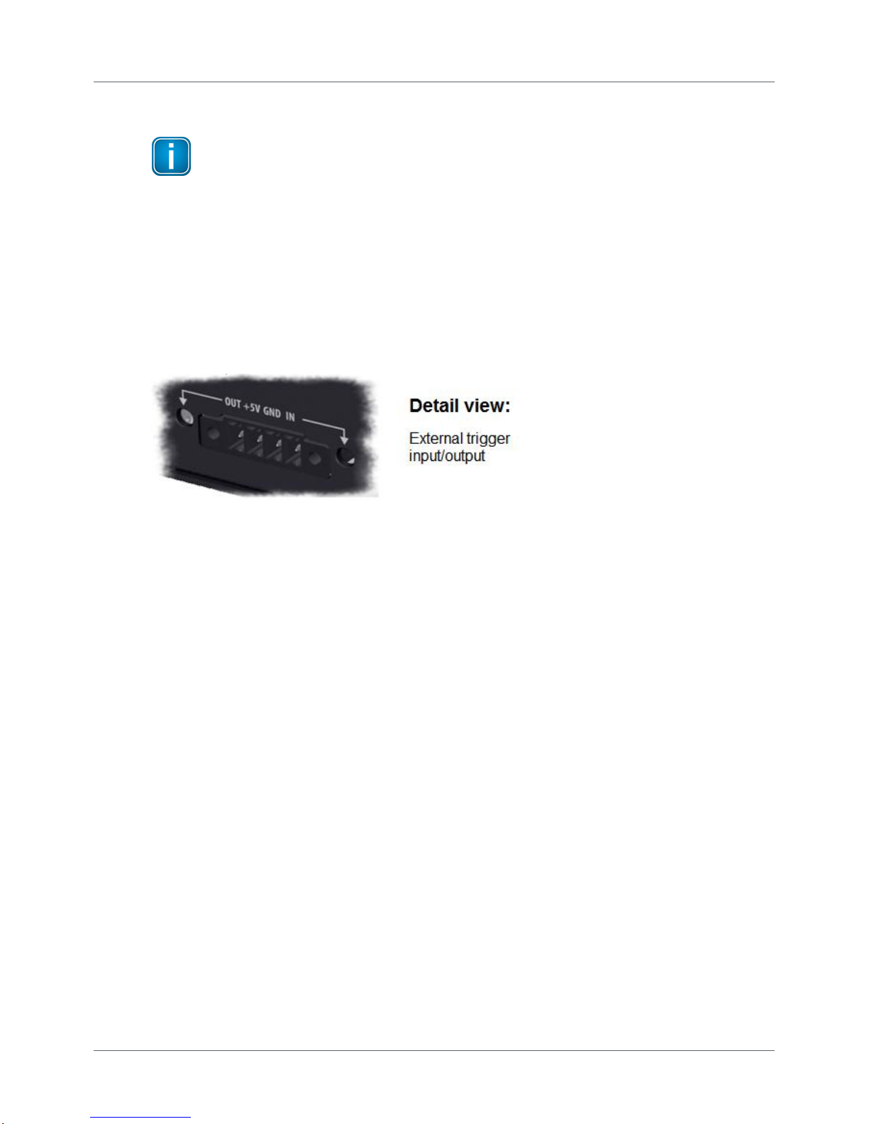
PROFIBUS Tester 5 (BC-700-PB) - User Manual
50
Copyright 2016 Softing Industrial Automation GmbH
11
Notes on external trigger input and output
The external trigger interface is for use in oscilloscope function. It is not related to logical
trigger conditions used for frame recording during protocol analysis.
The trigger output is "low active" and allows for triggering an external oscilloscope according to the
trigger conditions of the internal oscilloscope functionality (triggering on voltage level or address). Note
that the hardware driver at trigger output causes a small delay of the trigger signal.
Select the trigger condition "external trigger" in the PROFIBUS Diagnostics Suite, if you want to use the
trigger input (high-active) as trigger condition for the internal oscilloscope function. A rising edge at
trigger input initiates recording the signal.
The LEDs "OUT" and "IN" of the terminal block serve es optical control.
Figure 30: Terminal block of the BC-700-PB
Page 51

Chapter 12 - Notes on battery use
Copyright 2016 Softing Industrial Automation GmbH
51
12
Notes on battery use
12.1 General hints and warnings on rechargeable battery use
Read the following notes before using or charging your rechargeable battery pack.
Failure to read and follow the below instructions may result in fire, personal injury and
damage to property if charged or used improperly.
CAUTION
The rechargeable battery pack contains < 2 g Lithium.
Softing Industrial Automation GmbH, its distributors or retailers assume no liability for failures to
comply with these warnings and safety guidelines.
By purchasing this battery, the buyer assumes all risks associated with lithium batteries. If you do
not agree with these conditions, return the battery immediately before use.
Never charge batteries unattended. When charging the battery pack you should always remain in
constant observation to monitor the charging process and react to potential problems that may
occur.
Only charge the lithium battery pack when installed in the device and by using the delivered
external AC adapter.
If at any time you witness a battery starting to “balloon” or swell up, discontinue charging process
immediately, disconnect the battery and observe it in a safe place outside of any building or vehicle
and away from any combustible material for approximately 15 minutes. A swell up may cause the
battery to leak. The reaction with air may cause the chemicals to auto-ignition. This may result in
fire.
Avoid short circuits! Never place the cells on a conductive surface.
Cable short circuits can cause fire! If you accidentally short the wires, the battery must be placed in
a safe area for observation for approximately 15 minutes. Additionally, if a short occurs and contact
is made with metal (such as rings on your hand), severe injuries may occur due to conductibility of
electric current.
A battery can still self-ignite even after 10 minutes.
In the event of a crash, you must remove battery for observation and place in a safe open area
away from any combustible material for approximately 30 minutes.
Never store or charge battery pack inside your car in extreme temperatures. Extreme temperatures
can self-ignite the battery. Keep in mind the maximum allowed storage temperature. Refer to
Storage and Transportation .
Use caution to avoid puncture of the cell. Puncture of cells may cause fire.
You must not pull the wire leads when you carry or remove the battery from the device.
In case of cells being damaged, do not use the battery anymore!
Do not open the cells! Oxygen and lithium will heavily react with each other!
If the electrolyte gets in contact with your skin or with our eyes, wash immediately with water and
soap and seek medical advice.
53
Page 52

PROFIBUS Tester 5 (BC-700-PB) - User Manual
52
Copyright 2016 Softing Industrial Automation GmbH
Defective lithium ion batteries may evaporate substances which are harmful to health! Never
inhale!
For proper disposal ask your local recycling center or return battery packs to Softing. Do not ship
damaged battery packs. Contact our support department.
Do not throw into fire!
12.2 Charge battery
CAUTION
Never charge batteries unattended.
Only charge on fire-proof surfaces.
Only use the wide-range power supply (AC adapter) provided with the tool (see Delivery
scope) in order to charge the battery. Set voltage and current correctly. Failure to do so
can cause fire.
Follow the instructions from section General hints and warnings on rechargeable battery
use .
The internal battery is NOT being charged when connected to a USB port.
If the BC-700-PB indicates a low charge, proceed as follows:
1. Connect the external AC adapter (standard accessory) to a wall outlet.
2. Connect the external AC adapter to the BC-700-PB.
3. The BC-700-PB will automatically start charging. The power key on top of the BC-700-PB is going to
blink steadily during the charge process. The graphical display remains switched off. The device is
fully charged if the power key flares up very shortly.
Alternatively you may power on the device in order to receive additional information about the
charge process. The battery charge level indicator is located at the upper right corner of the screen:
the battery is being charged (white flash symbol).
the battery is fully charged - without mains charger connected.
the battery is fully charged - with mains charger connected.
4. You can disconnect the AC adapter from the device, then from the wall outlet. We recommend
switching off the device in order to save energy.
Hint
You do not need to charge the battery for a specific length of time. You can use the device
while it is charging.
9
51
Page 53

Chapter 12 - Notes on battery use
Copyright 2016 Softing Industrial Automation GmbH
53
12.3 Replace battery
Switch off device and disconnect charger
Always switch off the device and disconnect the charger before removing or installing the
battery.
1. Take a screwdriver (Philipps) and open the head screws on the back side of the device.
2. Remove the back cover.
Figure 31: Removing the back cover of BC-700-PB
3. Remove the integrated battery. For disposal refer to section Declarations by the manufacturer .
4. Make sure that the provided battery is free of damage such as missing insulation of wire leads,
puncture or deformation.
5. Insert the new battery. Connect the new battery. The connecting plug is protected against polarity
reversal.
6. Check that the connecting plug is properly connected.
7. Mount the back cover and fix the screws.
12.4 Discharge battery
The energy management of the device complies with the following recommendations for discharging
lithium ion batteries:
Do not discharge the battery more than 80 % of nominal capacity.
Do not discharge battery to a level below 3.5 V per cell without load. Deep discharge under load
below 3.3 V per cell can deteriorate the battery.
Discharge operating temperature: see Technical data (operating temperature).
12.5 Storage and transportation
Do not store the battery packs fully charged. If the battery is not used for more than one to two weeks,
consider the following notes on storage:
Store battery at 3.85V per cell (corresponds approx. 33% of the battery charge display, see Device
status )
Store at a temperature between 12°C/53F and 18°C/65F
Do not expose battery pack to direct sunlight.
Store in fireproof case or box.
56
55
31
Page 54

PROFIBUS Tester 5 (BC-700-PB) - User Manual
54
Copyright 2016 Softing Industrial Automation GmbH
CAUTION
Storing battery at temperatures greater than 77°C/170F for extended periods of time (more
than 2 hours) may cause damage to battery and possible fire.
12.6 Battery lifetime
Charging and discharging will typically wear out the battery pack over the time. Due to this aging the
usable battery capacity will decrease accordingly. Higher current loads and deep discharge processes
will considerably increase the aging process.
You will have best results with respect to battery life, if you
avoid deep discharging,
charge the battery properly,
store the battery at recommended temperatures,
avoid overloading,
switch off the device when not being used for a longer period of time.
12.7 Battery warranty
Misuse, abuse, incorrect charging and other inappropriate use of this product are not covered under
warranty.
Product warranty is limited to original defects in material and workmanship of the original and unused
battery pack!
12.8 Lithium backup battery
CAUTION
This product contains a lithium backup battery!
The lithium content is not more than 1 g. The battery has been successfully tested by the manufacturer
in accordance with the UN Manual of Test and Criteria (test procedures of Part III, Sub-Section 38.3).
Improper handling of lithium batteries can cause the batteries to ignite or explode and pose a burn
hazard to users. If the product is properly handled, this battery does not need to be replaced during the
lifetime of the product. Therefore, opening the product is unnecessary and not permitted. The product
must only be operated within the specified temperature range. Do not expose to heat above this
temperature range and keep away from open fire. Store in a dry place.
Page 55

Chapter 13 - Technical Data
Copyright 2016 Softing Industrial Automation GmbH
55
13
Technical Data
Power supply/
battery
Via external AC adapter 110 V .. 240 VAC 50/60 Hz (galvanically isolated)
or built-in three cells lithium ion accumulator with 11.1 VDC. The
rechargeable battery has a run-time of up to 5 hours (run-time depends
on the executed test functions and rate of wear of the rechargeable
battery) Battery is charged via external AC adapter.
RS485 (DP)
PROFIBUS D-sub connector (female), 9-pin, switchable power supply for
ext. bus termination Bus termination
Protocol and frame analysis: PROFIBUS DP and DPV1, automatic baud rate
detection 9.6 kbit/s .. 12 Mbit/s</t2>
Signal analysis:
PROFIBUS DP, DPV1, FMS and MPI;
signal quality index 0 .. 5000 determined from signal waveform as well
as signal/noise ration and rise time; Signal sampling with 8/16 samples per
bit
Oscillogram display:
test range ±5V at 10 mV resolution (differential), 0V…15V at 15mV
resolution (A or B to DGND)
Sampling rate up to 384 MSamples/s,
for signal details: 2,400 sampled points, for oscillogram analysis 8,192
sampled points
Topology scan: active, maximum distance 230 m, accuracy ±2 m
Cable test: active, permitted cable segment length 5 m ... 1500 m,
accuracy 5%</t2>
USB
V 2.0, high speed 480 Mbit/s, galvanically isolated
Trigger
IN: L=0 .. 0,8 V; H=2,4 .. 24 V; pulse > 10 µs, active high
OUT: ca. 5 V, active low (connection to storage oscilloscope)
Internal memory
capacity
3 network directories for storing Quick Tests, cable tests and trend logs
Trend logging max. 99 hours
Dimensions
HxWxD: 35 x 220 x 110 mm
Weight
Test tool without cable: approx. 0.75 kg,
complete with carrying case, without accessories: approx. 4.2 kg
Protection class
IP 20
Permissible
ambient conditions
Operating temperature 0 ... 50 °C
Storage temperature -20 ... 70 °C
Air humidity 10 ... 90 % without condensation
Conformity
CE, FCC, VCCI
Operation
Via graphical color display, four function keys and scroll wheel including
central push-button or via PC/notebook.
Display languages available: German, English
PC operating
software
PROFIBUS Diagnostics Suite, see separate documentation
Page 56

PROFIBUS Tester 5 (BC-700-PB) - User Manual
56
Copyright 2016 Softing Industrial Automation GmbH
14
Declarations by the manufacturer
This device complies to the EU product directive 2004/108/EC according to the following directives:
Reference number
Description
EN 55011:2009 +
A1:20102, Class A
Industrial, scientific and medical equipment - Radio-frequency disturbance
characteristics - Limits and methods of measurement, class A
EN 55022:2010, Class
A
Information technology equipment - Radio disturbance characteristics - Limits
and methods of measurement, class A
EN 61000-6-2:2005
Electromagnetic compatibility (EMC) - Part 6-2: Generic standards - Immunity
for industrial environments
EN 61000-6-4:2007 +
A1:2011
Electromagnetic compatibility (EMC) - Part 6-4: Generic standards - Emission
standard for industrial environments
EN 61326-1:2013
Electrical equipment for measurement, control and laboratory use - EMC
requirements - Part 1: General requirements
EN 50581:2012
Technical documentation for the assessment of electrical and electronic
products with respect to the restriction of hazardous substances
A Declaration of Conformity in compliance with the above standards has been made and
can be requested from Softing Industrial Automation GmbH.
CAUTION
This is a Class A product. In a domestic environment this product may cause radio
interference in which case the user may be required to take adequate measures!
ROHS
The PROFIBUS Tester 5 (BC-700-PB) device is ROHS compliant.
WEEE
Electrical and electronic equipment must be disposed of separately from normal waste at
the end of its operational lifetime.
Please dispose of this product according to the respective national regulations or
contractual agreements. If there are any further questions concerning the disposal of this
product, contact Softing Industrial Automation.
Note
To fulfill the EMC requirements, the other components (AC adapter, PROFIBUS stations,
etc.) also have to meet the EMC requirements. A shielded cable must be used. In addition,
the cable shield must be grounded properly.
Note
Additional tests have been performed successfully proving compatibility with the
requirements set forth by FCC and VCCI.
Page 57

Copyright 2016 Softing Industrial Automation GmbH
Index
57
Index
- A -
Accessory
optional ~ 10
Activate
License 39
Activate license 39
Activated licenses 39
- B -
Backup battery 54
Battery
charge 52
discharging 53
general hints 51
notes on use 51
replace 53
spare ~ 12
storage 53
warnings 51
warranty 54
Battery charge level indicator 31
- C -
Cable structure
for testing in PA networks 11
Cable test
assessment criteria 44
fault indications 44
remedial measures 44
tips and tricks 44
Carrying case
Content 9
Connection
to bus 26
Conventions used
Buttons 7
Menu commands 7
Program code 7
- D -
Data
technical ~ 55
Delivery scope 9
D-sub adapter cable 10, 18
D-sub connection 12
- F -
Fieldbus Shield Digital Leakage Current Clamp 11
Firmware update 39, 40
- H -
H1 adapter 11
- I -
Import data 38
Importing
Data to PC 38
- L -
License Manager 39
Live bus
analyzing 25
testing 18
testing (DP) 20
- M -
M12 adapter set 11
M12 connection 13
Measurement status 31
Menüs 32
- O -
Operation mode
return to ~ 16
- P -
PA adapter 25
Power down
automatically 16
manually 16
- Q -
Quality index 49
Page 58

Index
Copyright 2016 Softing Industrial Automation GmbH
58
- R -
Related documents 7
- S -
Service interface 12
Sleep mode 16
Softkeys 30
Stand-alone mode 29
- T -
Test status 31
Trigger input 50
Troubleshooting 42
Page 59

This page is intentionally left blank.
Copyright 2016 Softing Industrial Automation GmbH
59
Page 60

Tel: + 49 89 45 656-0
Fax: + 49 89 45 656-488
info.automation@softing.com
Richard-Reitzner-Allee 6
85540 Haar / Germany
Softing Industrial Automation GmbH
http://industrial.softing.com
 Loading...