

SofTec Microsystems ST7 Series, PK-ST7FLITE2 User Manual


PK-ST7FLITE2
Starter Kit for
STMicroelectronics
ST7FLITE2
User’s Manual
Copyright © 2004 SofTec Microsystems®
DC00746

We want your feedback!
SofTec Microsystems is always on the lookout for new ways to improve its Products and
Services. For this reason feedback, comments, suggestions or criticisms, however small,
are always welcome.
SofTec Microsystems
E-mail (general information): info@softecmicro.com
E-mail (marketing department): marketing@softecmicro.com
E-mail (technical support): support@softecmicro.com
Web: http://www.softecmicro.com
Important
SofTec Microsystems reserves the right to make improvements to the PK Series of Starter Kits, their documentation and
software routines, without notice. Information in this manual is intended to be accurate and reliable. However, SofTec
Microsystems assumes no responsibility for its use; nor for any infringements of rights of third parties which may result
from its use.
SOFTEC MICROSYSTEMS WILL NOT BE LIABLE FOR DAMAGES RESULTING FROM LOSS OF DATA, PROFITS,
USE OF PRODUCTS, OR INCIDENTAL OR CONSEQUENTIAL DAMAGES, EVEN IF ADVISED OF THE POSSIBILITY
THEREOF.
Trademarks
ST is a trademark of STMicroelectronics.
Microsoft and Windows are trademarks or registered trademarks of Microsoft Corporation.
PC is a registered trademark of International Business Machines Corporation.
Other products and company names listed are trademarks or trade names of their respective companies.
Written by Paolo Xausa

PK-ST7FLITE2 User's Manual
Contents
1. Overview 5
What is the PK-ST7FLITE2 Starter Kit? 5
ST7FLITE2 Built-In Debug Features 6
PK-ST7FLITE2 Board Layout 7
STVD7 Integrated Development Environment 8
Metrowerks and Cosmic Demo Versions 9
Recommended Reading 9
Software Upgrades 9
2. Getting Started 11
PK-ST7FLITE2 Components 11
Host System Requirements 11
Installing the Software 12
Installing the Hardware 12
Application Tutorial 13
Additional Examples 16
3. Hardware Features 17
Introduction 17
MCU Section 17
USB to ICC Interface 18
Demo Section 18
Prototype Area 19
4. Debugging Features 21
Limitations 21
Configuring the MCU 21
Hardware Model Settings 22
Device and Option Bytes Settings 25
Breakpoint Notes 25
Instruction Breakpoints and Advanced Breakpoints 26

Contents
Advanced Breakpoints Limitations 27
DataBlaze Programming Utility 28
5. Troubleshooting 31
Common Problems and Solutions 31
Communication can’t be established with PK-ST7FLITE2 31
A communication error is returned on a program execution command (Run,
Continue, Step, etc.) 32
The program execution stops at the beginning of user’s code 32
The program execution stops at an unexpected location 32
Getting Technical Support 33
Appendix A. Electrical and Physical Specifications 35
Appendix B. Clock Source Options 37
Overview 37
Internal RC Oscillator 37
External crystal/ceramic resonator 39
External Clock Input 39

PK-ST7FLITE2 User's Manual
1. Overview
What is the PK-ST7FLITE2 Starter Kit?
The PK-ST7FLITE2 Starter Kit is an entry level tool which allows you to get started with the
STMicroelectronics ST7FLITE2 microcontroller.
The main features of the ST7FLITE2 microcontroller are:
§ Up to 8-MHz ST7 CPU (with a 16-MHz external oscillator);
§ 8 KB of FLASH memory;
§ 384 bytes of RAM;
§ 256 bytes of EEPROM;
§ 7-channel, 10-bit analog-to-digital converter (ADC);
§ One synchronous serial interface (SPI);
§ Clock source options include crystal/ceramic resonator, external clock or internal RC
oscillator;
§ Watchdog timer, two 8-bit Lite timers, one 12-bit auto-reload timer with four PWM
outputs;
§ Up to 15 multifunctional bi-directional I/O lines;
§ 7 high-sink outputs;
§ Integrated Debug Module (DM);
§ Input voltage range from 2.4 V to 5.5 V;
The PK-ST7FLITE2 Starter Kit has been designed for the evaluation of the ST7FLITE2
microcontroller and the debugging of small user applications.
The PK-ST7FLITE2 Starter Kit takes advantage of the STMicroelectronics Visual Debug
Integrated Development Environment (STVD7, which groups an Editor, Assembler and
Debugger), and the ST7FLITE2 built-in debug features, which allow the download and
debug of the user application into the microcontroller’s FLASH memory.
1
Page 5

1
1. Overview
The PK-ST7FLITE2 Starter Kit also includes the evaluation versions of the Metrowerks and
Cosmic C compilers for ST7, which seamlessly integrate with STVD7.
Together with STVD7, PK-ST7FLITE2 provides you with everything you need to write,
compile, download, in-circuit emulate and debug user code. Full-speed program execution
allows you to perform hardware and software testing in real time. PK-ST7FLITE2 is
connected to the host PC through a USB port. A prototyping area allows you to wire your
own small application.
PK-ST7FLITE2 offers you the following benefits:
§ Real-time code execution;
§ In-circuit debugging;
§ In-system programming and debugging through a ICC-compatible interface;
§ Demo area with push-buttons, potentiometer and user LEDs;
§ Prototyping area.
Note: the PK-ST7FLITE2 starter kit has been designed for evaluation purposes only. For
serious debugging, we suggest you to switch to the SofTec Microsystems inDART-STX
Series of debugging/programming tools.
ST7FLITE2 Built-In Debug Features
The ST7FLITE2 microcontroller features an ICC (In-Circuit Communication) serial interface
module which allows to communicate with a host device through two dedicated pins
(ICCDATA and ICCCLK). By means of ICC commands, a host device can program data
into/read data from the microcontroller, retrieve CPU register contents, and run the user
program.
Additionally, a dedicated peripheral (the Debug Module, or DM) is hard-wired in the device
and allows advanced debugging features like single-step execution and advanced
breakpoints.
All these features allow the implementation of low-cost, real-time emulation solutions, like
the PK-ST7FLITE2 Starter Kit. As a bonus, the PK-ST7FLITE2 Starter Kit features a USB-
Page 6

PK-ST7FLITE2 User's Manual
to-ICC circuitry which allows the host PC to communicate to the microcontroller through a
standard USB cable.
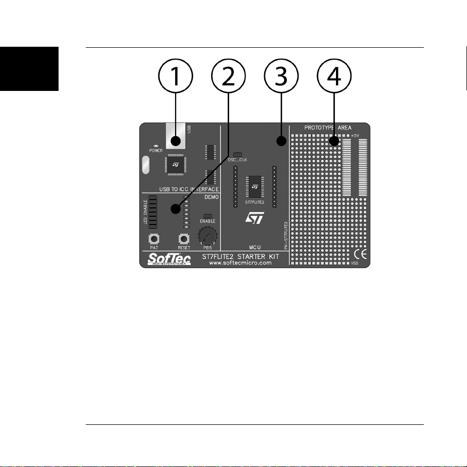
PK-ST7FLITE2 Board Layout
The PK-ST7FLITE2 board has the following hardware features:
1. A “USB to ICC Interface” section. It contains the circuitry needed to electrically and
logically translate ICC-like commands sent by the host PC through the USB cable to the
ICC interface of the microcontroller. The PK-ST7FLITE2 board is powered by the USB
bus.
2. A “Demo” section. It features a RESET push-button, one user push-button, a
potentiometer and eight user LEDs.
3. A “MCU” section. It contains a soldered, 20-pin ST7FLITE2 device (in SOIC package)
with connectors to access the I/O pins of the microcontroller for expansion prototyping.
4. A “Prototype” section. You can wire your own circuit here. The prototype section
features both a standard, thru-hole area (for mounting traditional components) and a
SMD area (for soldering SMD components in SOIC package).
1
Page 7
1
1. Overview
The PK-ST7FLITE2 Board
STVD7 Integrated Development Environment
The PK-ST7FLITE2 user interface is based on the ST7 Visual Debug Integrated
Development Environment (STVD7). STVD7 enables programs to be executed and stopped
where desired, while viewing the memory contents. It offers the ability to step through and
examine code at the C source level and the Assembly instruction level. You can introduce
breakpoints and run or single-step the executable, while viewing the source and observing
current program values. All registers and memory locations are accessible for both read and
write operations. This documentation covers the basic setup and operation of the STVD7,
but it does not cover all of its functions. For further information, please refer to the STVD7
on-line help.
Page 8

PK-ST7FLITE2 User's Manual
Metrowerks and Cosmic Demo Versions
Both of these third-party companies have developed a C compiler for use with ST7
microcontrollers. A demo version of each compiler is present on the SofTec Microsystems
PK-ST7FLITE2 “System Software” CD.
Recommended Reading
This documentation describes how to use PK-ST7FLITE2 together with the
STMicroelectronics STVD7 IDE. Additional information can be found in the following
documents:
§ PK-ST7FLITE2 Schematic.
§ STVD7 Online Help—The ST7 Visual Debug online help.
§ AST7-LST7.PDF— This user’s guide describes how to use the STMicroelectronics
assembler, linker, formatter and librarian for the ST7 family.
§ ST7 FAMILY 8-BIT MCUs Programming Manual—Programming reference containing
the description of the full ST7 instruction set.
§ STMicroelectronics ST7 Datasheets.
Software Upgrades
The latest version of the PK-ST7FLITE2 system software is always available free of charge
from our website: http://www.softecmicro.com.
1
Page 9


2. Getting Started
PK-ST7FLITE2 User's Manual
PK-ST7FLITE2 Components
The PK-ST7FLITE2 package includes the following items:
1. The PK-ST7FLITE2 evaluation board;
2. A USB cable;
3. The SofTec Microsystems PK-ST7FLITE2 “System Software” CD-ROM;
4. A “QuickStart Tutorial” color poster;
5. This user’s manual.
Host System Requirements
The PK-ST7FLITE2 in-circuit debugger is controlled by an Integrated Development
Environment running under Windows (STVD7). The following hardware and software are
required to run the STVD7 user interface together with PK-ST7FLITE2:
1. A PC compatible system running Windows 98, Windows Me, Windows 2000 or
Windows XP;
2. 64 MB of available system RAM plus 40 MB of available hard disk space;
3. A USB port;
4. A CD-ROM drive (for installation).
2
Page 11

2
2. Getting Started
Installing the Software
Note: before connecting the PK-ST7FLITE2 board to the PC, it is recommended you first
install all of the required software (see below), so that the PK-ST7FLITE2 USB driver will be
automatically found by Windows when you connect the board.
The PK-ST7FLITE2 user interface setup program is located on the SofTec Microsystems
“System Software” CD-ROM provided with the instrument. The setup program will copy the
required files (including the USB driver) to your hard drive.
To install the PK-ST7FLITE2 user interface:
1. Insert the “System Software” CD-ROM into your computer’s CD-ROM drive.
2. A startup window should automatically appear (if the startup window doesn’t appear
automatically, manually run the Setup.exe file located on the CD-ROM root). Choose
“Install Instrument Software” from the main menu.
3. A list of available software should appear. Click on the “Install PK-ST7 Series” option.
4. Follow the on-screen instructions.
Note: if you are installing the PK-ST7FLITE2 system software on Windows 2000 or
Windows XP you must have logged in as Administrator.
Installing the Hardware
The PK-ST7FLITE2 board is connected through a USB port to a host PC. Connection steps
are listed below in the recommended flow order:
1. Install all the required system software as described in the previous section.
2. Insert one end of the USB cable into a free USB port.
Page 12
 Loading...