


sumes no responsibility for its use; nor for any infringements
IDB-HC08JL
Evaluation Board
For Motorola MC68HC908JL
User’s Manual
1. Introduction
Copyright © 2002 SofTec Microsystems®
DC00525
Overview
The IDB-HC08JL Evaluation Board demonstrates the capabilities of the
28-pin MC68HC908JL devices. The IDB-HC08JL Evaluation Board can
be used as a standalone application or with an emulator system, such as
inDART-HC08, through a MON08-compatible connection.
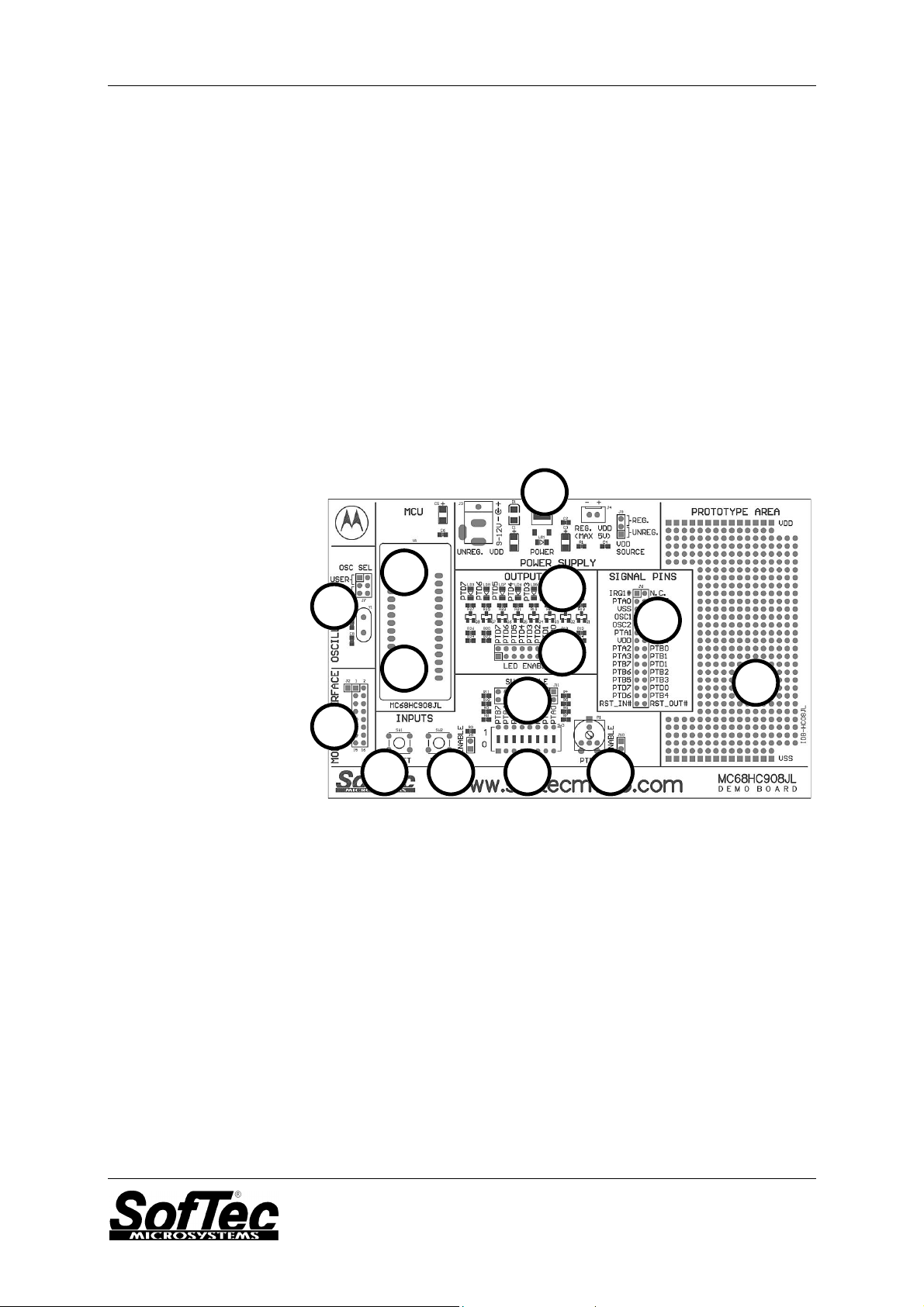
Board Features
The IDB-HC08JL Evaluation Board has the following hardware features:
1. An MC68HC908JL3 microcontroller (in DIP28 package, already
programmed with a demo application—in addition, you can also use
any of the MC68HC908JL family devices);
2. ZIF socket for the microcontroller;
3. A standard MON08 connector;
4. Eight jumpers to connect/disconnect each of the eight LEDs to/from
their respective Port D pins;
5. Eight high-efficiency (low-current) LEDs connected to Port D;
SofTec Microsystems
E-mail (general information): info@softecmicro.com
E-mail (marketing department): marketing@softecmicro.com
E-mail (technical support): support@softecmicro.com
Web: http://www.softecmicro.com
Important
SofTec Microsystems reserves the right to make improvements to its products, their documentation and software routines, without notice. Information
in this manual is intended to be accurate and reliable. However, SofTec Microsystems as
of rights of third parties which may result from its use.
SOFTEC MICROSYSTEMS WILL NOT BE LIABLE FOR DAMAGES RESULTING FROM LOSS OF DATA, PROFITS, USE OF PRODUCTS, OR
INCIDENTAL OR CONSEQUENTIAL DAMAGES, EVEN IF ADVISED OF THE POSSIBILITY THEREOF.
Trademarks
inDART is a trademark of SofTec Microsystems.
Microsoft and Windows are trademarks or registered trademarks of Microsoft Corporation.
PC is a registered trademark of International Business Machines Corporation.
Other products and company names listed are trademarks or trade names of their respective companies.
IDB-HC08JL User's Manual
12 13 14 10
6. A potentiometer, together with a jumper to connect/disconnect it
to/from PTB3;
7. A push-button switch connected to RESET;
8. A push-button switch, together with a jumper to connect/disconnect it
to/from PTA4;
9. Eight jumpers to connect/disconnect each of the eight DIP-switches
to/from their respective PTA/PTB pins;
10. Eight general-purpose DIP-switches connected to PTA/PTB;
11. A 16-MHz crystal oscillator, together with two jumpers to
connect/disconnect it from the microcontroller’s OSC1 and OSC2
pins;
12. A connector for a 9-12-V, 200-mA (unregulated) power supply and an
auxiliary power supply connector for a 5-V (max., regulated), together
with a jumper to select the power supply source;
13. A connector area to access the I/O pins of the microcontroller for
expansion prototyping;
14. A prototyping area.
1
5
11
4
2
9
3
6 7 8
The IDB-HC08JL Demo Board
Supported Devices
The IDB-HC08JL Evaluation Board supports the following devices:
§ MC68HC908JL3;
§ And any future MC68HC908JL family pin-to-pin compatible device.
Recommended Reading
Motorola MCU CD-ROM or individual datasheet;
Motorola CPU08 Central Processor Unit Reference Manual;
inDART-HC08 User’s Manual.
Page 2
2. Getting Started
Overview
The IDB-HC08JL Evaluation Board may be used as a standalone
application or with a MON08-based emulator/programmer (host mode).
Standalone Mode
The IDB-HC08JL Evaluation Board comes with the microcontroller preprogrammed with a sample application. When working in standalone
mode, the sample application configures the A/D peripheral to convert on
the A/D channel connected to the potentiometer and displays the results
on the LEDs.
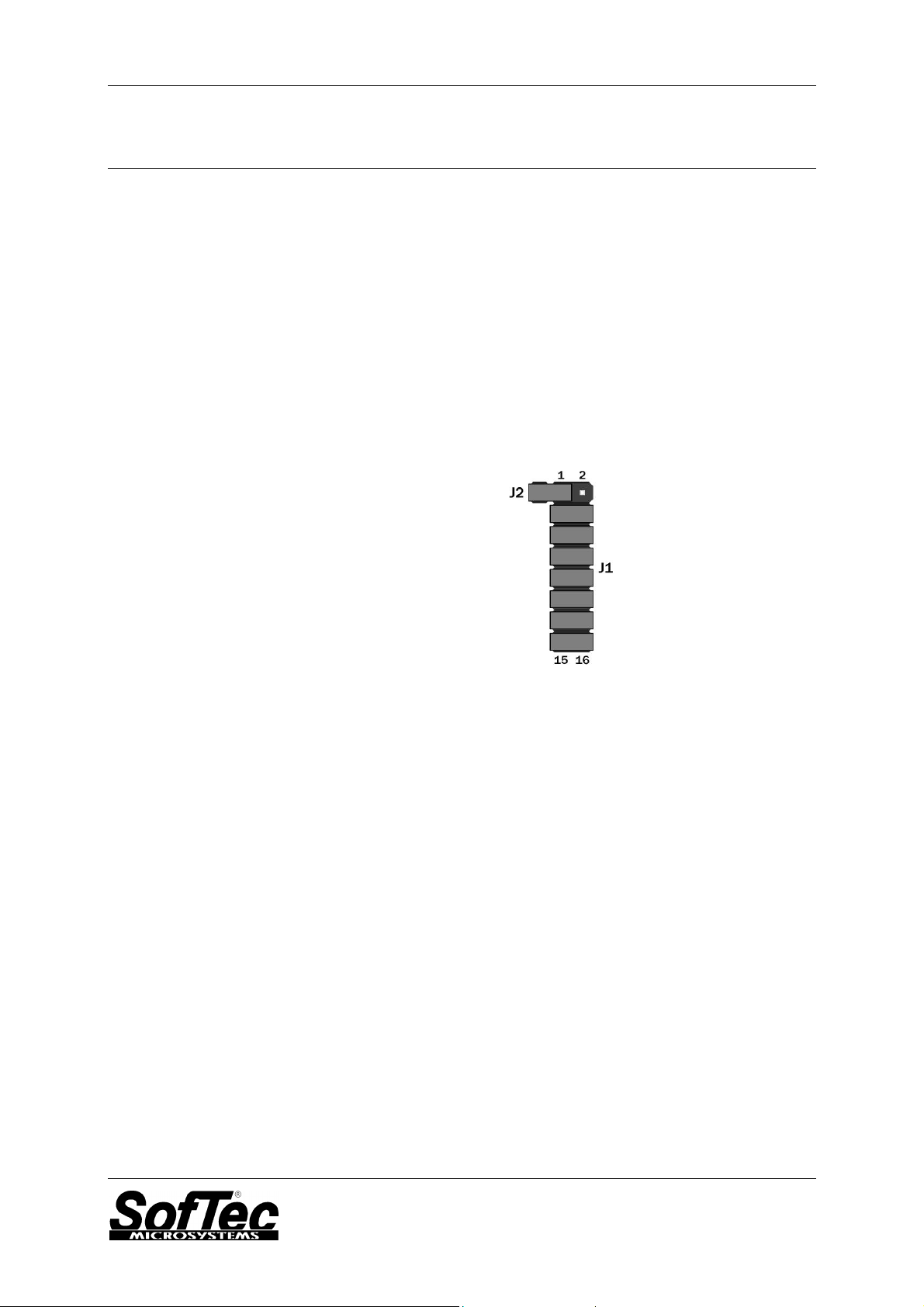
In order for the IDB-HC08JL Evaluation Board to work in standalone
mode, the MON08 connector’s pins must be jumpered as show below
(factory setting).
IDB-HC08JL User's Manual
MON08 Connector Jumpered for Standalone Mode Operation
Additionally, you must verify that the board’s other jumpers are set
correctly.
§ Make sure that the “OSC SEL” (J7) jumper selects the “XTAL”
position. This is needed to enable the on-board 16-MHz crystal
oscillator.
§ Make sure that all of the “LED ENABLE” jumpers (J8) and the
“POTENTIOMETER ENABLE” jumper (J10) are inserted.
§ Make sure that the pre-programmed sample device is in the
appropriate socket on the board. Finally, power up the board. The
IDB-HC08JL Evaluation Board can be powered either via the
“UNREG. VDD” connector (J3) or the “REG. VDD” connector (J4).
The “UNREG. VDD” connector accepts 9-12 V DC, 200-mA wall plug-in
power supply with a 2.1 mm pin and sleeve plug with positive in the
center and sleeve as ground. When powering the board through this
connector, make sure the “VDD SOURCE” connector (J5) selects the
“UNREG.” Position. The “UNREG. VDD” voltage is internally regulated to
5 V DC.
The “REG. VDD” connector accepts 5 V DC (max.). When powering the
board through this connector, make sure the “VDD SOURCE” connector
(J5) selects the “REG.” Position. The “REG. VDD” voltage directly powers
the microcontroller and the rest of the board.
Page 3

IDB-HC08JL User's Manual
Upon powering up the board, the green “POWER” LED turns on. By
rotating the potentiometer, you affect the results of the A/D conversion,
and the value of each conversion is displayed (in a linear bar fashion) on
the LEDs.
Host Mode
The IDB-HC08JL Evaluation Board can be used in conjunction with a
MON08-based emulator/programmer, such a SofTec Microsystems’
inDART-HC08 In-Circuit Debugger/Programmer or a Motorola
development tool.
If you use the evaluation board with SofTec Microsystems’ inDARTHC08, a sample application similar to that described in the previous
section can be executed in “Host” mode, where the program execution is
controlled by the host PC. You can use the PC, additionally, to debug the
application by, for example, execute the program step by step and
watching how the microcontroller registers vary, by using the Metrowerks’
CodeWarrior HC08 IDE provided with inDART-HC08. The example is
available both in Assembly and in C language. Please refer to the
inDART-HC08 user’s manual for a step-by-step tutorial.
In order to work with an emulator/programmer, the jumpers in the MON08
connector must be removed, and the MON08 cable of the
emulator/programmer must be connected to the evaluation board’s
MON08 connector (J1) connector, taking care of the proper polarity. The
J2 connector is not used in this mode.
3. MON08 Connections (J1 Connector)
Pin # Pin Name Description
1 RST_OUT# Reset signal to target system: GND or open drain output
2 GND System ground.
3 RST_IN# Reset signal from target system: GND to VDD input to control
4 RST# MCU reset; held at VPP (or VDD, depending on the target
5 TGT_IRQ# Interrupt signal from target system: GND to VDD input to control
6 IRQ# MCU interrupt; held at VPP when the TGT_IRQ# signal is not
7 None N.C.
8 None N.C.
9 TGT_PTB0 Port B, bit 0; reserved MCU connection (unavailable to
10 PTB0 Port B, bit 0; MON08 single-wire communication.
11 TGT_PTB1 Port B, bit 1.
12 PTB1 Port B, bit 1; held at VDD during reset.
13 TGT_PTB2 Port B, bit 2.
14 PTB2 Port B, bit 2; grounded during reset.
15 TGT_PTB3 Port B, bit 3.
16 PTB3 Port B, bit 3; held at ground or VDD during reset, depending on
reflecting the state of the MCU RST# and RST_IN# signals.
the state of the MCU RST# and RST_OUT# signals.
microcontroller) out of reset. No other target-system logic
should be tied to this signal.
the state of the MCU IRQ# signal.
asserted.
application).
the “Frequency Divider” parameter (see inDART-HC08 User’s
Manual).
MON08 Signals
Page 4

VDD
RED
LD9
PTD7R26
R27
470R
Q8
BSS138
10K
LD1
VDD
J5
123
(REG.)
1
2
J4
REG. VDD
MAX 5V (UNREG.)
LD8
R25
Q7
BSS138
R1
GRREN
POWER
C4
C3
+
VDD SOURCE
U2
D1
VSS
J3
470R
3
1
470R
VOUT
VIN
PTD6R24
100nF
10uF
RED
10K
C2
C1
+
GF1M
312
GND
LD7
R23
Q6
BSS138
2
78M05
100nF
10uF
9-12V
UNREG. VDD
470R
RED
PTD5R22
10K
VSS
RED
LD6
PTD4R20
R21
470R
Q5
BSS138
10K
J8
1 2
PTD7
POWER SUPPLYSIGNAL PINS
LD5
3 4
PTD6
Q4
5 6
PTD5
VDD
R19
BSS138
7 8
PTD4
9 10
PTD3
U1
470R
PTD3R18
11 12
PTD2
PTB0
21
7
VDD
RED
10K
13 14
PTD1
PTB1
C6
C5
+
PTB120PTB0
15 16
PTD0
PTB2
18
100nF
10uF
LD4
R17
Q3
LED ENABLE
PTB3
PTB4
PTB415PTB317PTB2
PTA0
PTA16PTA28PTA3
2
PTA0
PTA1
BSS138
PTB6
PTB5
9
PTA2
PTA3
VSS
470R
J7A
RED
PTD2R16
LD3
10K
PTD7
PTB7
PTB710PTB611PTB512PTD713PTD6
OSC2
PTA4
PTA5
5
23
27
PTA5
PTA4
OSC SEL
135
(XTAL)
(USER)
OSC2
C7
Q2
PTD6
14
R2
Y1
22pF
R15
BSS138
PTD5
J7B
10M
16MHz
C8
470R
PTD4
26
PTD525PTD4
OSC1
4
(XTAL)
PTD1R14
PTD3
22
PTD3
RED
10K
PTD1
PTD2
19
24
PTD2
IRQ1#
1
IRQ#
246
(USER)
OSC1
22pF
VSS
LD2
Q1
PTD0
16
PTD1
PTD0
RST#
28
RST#
OSC SEL
R13
BSS138
3
VSS
RED
PTD0R12
470R
10K
VSS
MC68HC908JL
OUTPUTS
VSS
MCU
VDD
SW3
J11
VDD
VDD
8
9
1 2
PTA0
3 4
PTA1
5 6
PTA2
R3
7 8
9 10
PTA3
PTB4
P1
J10
1 2
TGT_PTB3
10K
J9
1 2
PTA4
PTB3
11 12
PTB5
13 14
PTB6
1K
ENABLE
ENABLE
1234567
16151413121110
15 16
PTB7
SW2
SW
SW ENABLE
PTA4
R11
10K
R10
10K
R9
10K
R8
10K
VSS
R7
10K
R6
10K
R5
10K
R4
10K
VSS
IDB-HC08JL Sheet: 1/1Date: 27/09/2002ID: SD00281
INPUTS
VSS
J6
(N.C.)
PTA5
3 4
PTA0
TGT_IRQ#1 2
(IRQ1#)
PTD4
5 6
VSS
PTD5
7 8
OSC1
PTD2
9 10
OSC2
PTA4
11 12
PTA1
(PTB0)
TGT_PTB0
PTD3
13 14
15 16
VDD
PTA2
(PTB1)
(PTB2)
TGT_PTB2
TGT_PTB1
PTD1
17 18
19 20
21 22
PTB7
PTB6
PTA3
(PTB3)
PTB4PTD6
TGT_PTB3
PTD0
23 24
25 26
27 28
PTB5
PTD7
RST_OUT#
29 30
RST_IN#
VSS
RST#
IRQ#
PTB0
PTB1
PTB2
PTB3
J1
J2
1 2
3 4
5 6
7 8
RST_OUT#
RST_IN#
TGT_IRQ#
9 10
11 12
13 14
TGT_PTB0
TGT_PTB1
TGT_PTB2
15 16
TGT_PTB3
MON08 INTERFACE OSCILLATOR
1
RST#
RST_IN#
SW1
RESET
VSS
www.softecmicro.com
 Loading...