


USER MAINTENANCE GUIDE
MAN023.012
MINI 900/950
JANUARY 2009
This document can not be reproduced or released without the sodikart authorization.
CONFIGURE THE KART ACCORDING TO THE GUIDE INSTRUCTIONS
USE SPARE PARTS OF SODIKART ORIGIN

T
MINIKART MANUAL
SUMMARY
SAFETY INSTRUCTIONS 3
PREPARING THE ASSEMBLY
1- GETTING MINIKART OUT OF THE PACKING 4
2- TOOLS FOR ASSEMBLY 5
3- MAINTENANCE PRODUCTS 5
SEQUENCE OF ASSEMBLY 6
4- ASSEMBLY OF THE STEERING WHEEL 7
5- ASSEMBLY OF THE FUEL TANK AND THE OVERFLOW BOTTLE 8
6- ASSEMBLY OF THE SEAT 9
7- ASSEMBLY OF THE BODYWORK 11
8- STARTING YOUR MINIKART 13
STANDARD ADJUSTMENTS
9- ADJUSTMENT OF THE FRONT 14
10- ADJUSTMENT OF THE REAR 17
11- ADJUSTMENT OF THE SEAT 19
MAINTENANCE
12- TYRES 20
13- HYDRAULIC BRAKE 21
14- MECHANICAL BRAKE 22
15- CLEANING THE CHASSIS 24
16- MAINTENANCE PLAN 25
17- TROUBLE SHOOTING 26
his document can not be reproduced or released without the SODIKART authorization.
VERSION : JANUARY 2009 1/26 MAN023.012

MINIKART MANUAL
You have decided to acquire a SODI chassis. We would like to thank you for choosing the SODI
MINIKART.
Your kart has been developed for performance and safety.
It is the outcome of SODIKART’s experience and of the latest research at the highest level of
competition.
This manual contains instructions for the assembly and the maintenance of your kart, according
to the rules of the art.
Safety on a track is a personal and collective matter at the same time: taking care of your
MINIKART is the first guarantee of your safety and of the safety of other pilots.
This manual also contains advice about adjustments.
Their purpose is to help you exploiting all the potential of your MINIKART.
Enjoy driving your MINIKART,
VERSION : JANUARY 2009 2/26 MAN023.012

MINIKART MANUAL
SAFETY INSTRUCTIONS
The MINIKART has been designed for leisure and high level competition.
Its design, which complies with the pending rules of the CIK, ensures an optimum safety in
normal working conditions.
Its high speed and performances imply a proper maintenance.
• For your safety and the one of other pilots, please thoroughly respect :
- The assembly instructions.
- The adjustment recommendations.
- The maintenance plan.
• Please pay especial attention to the instructions or comments to the following symbols
below :
NOTE: Gives useful information.
: indicates a high risk of severe injury if the instructions are not
followed.
¾ Should you not find an answer to your questions in this manual or face any problem, please
get advice from the SODIKART distribution network.
¾ The SODI MINIKART is designed for safety and reliability in normal conditions of use.
Before using it, please read this manual and carefully follow the instructions. By not
doing so, you might be exposed to a risk of severe, even fatal injury, and your kart
might suffer damages.
¾ The SODI chassis can only be used on an approved track and by a driver who is in
possession of a valid membership card of the go-kart’s federation of his own country.
¾ Prior to going on the track, please check all points related to safety.
¾ In order to avoid fire, put the kart at least one meter away from the buildings. Never
leave inflammable objects close to the kart.
¾ If fuel has been poured, wipe and wait for vapors to dissipate, before starting the
kart.
¾ Kids and domestic animals have to be kept away from the kart and the track.
¾ Never drive the kart without adequate pilot equipment.
¾ Use spare parts of SODIKART origin.
VERSION : JANUARY 2009 3/26 MAN023.012

MINIKART MANUAL
1- GETTING MINIKART OUT OF THE PACKING
STEERING WHEEL
SEAT
LEFT SIDE POD
LEFT SIDE POD
SUPPORT
RIMS
STEERING COLUMN
NOTE:
SPOILER NASSEAU PANEL
ASSEMBLY
- Prior to assembling your kart, check the above described elements and
familiarize yourself with them.
- The part numbers of the various items can be found in the “spare parts
catalogue “.
OVERFLOW
BOTTLE
RIGHT SIDE POD
RIGHT SIDE POD
SUPPORT
FUEL TANK
MINIKART 900/950
VERSION : JANUARY 2009 4/26 MAN023.012

MINIKART MANUAL
2-TOOLING FOR ASSEMBLY AND ADJUSTMENT
DESIGNATION DIAMETER PART NUMBER
- T handle wrench allen key 4mm OU 911.002
- T handle wrench allen key 5 mm OU 911.003
- T handle wrench allen key 6 mm OU 911.004
- T handle wrench allen key 8 mm OU 911.005
- T handle socket spanner 8 mm OU 912.004
- T handle socket spanner 10 mm OU 912.001
- T handle socket spanner 11 mm OU 912.002
- T handle socket spanner 13 mm OU 912.003
3- MAINTENANCE PRODUCTS
- Cleaner : (paint - plastics) : LU 832.007
- WD 40 LU 833.003
- Grease for chain LU 822.002
NOTE:
FOR OTHER TOOLS, ACCESSORIES AND EQUIPMENTS PLEASE REFER TO THE ITAKA
CATALOGUE.
VERSION : JANUARY 2009 5/26 MAN023.012

MINIKART MANUAL
SEQUENCE OF ASSEMBLY AND INSTRUCTIONS
STEERING WHEEL (chapter 4).
FUEL TANK AND OVERFLOW BOTTLE (chapter 5).
SEAT (chapter 6).
BODYWORK (chapter 7).
NOTE:
Recommended tightening torques:
Ø6 = 10 to 12 m.N
Ø8 = 12 to 24 m.N
Ø10 = 24 to 48 m.N
Do not overtighten screws and bolts
Screws without bolts are to be blocked with 1 drop of special glue (LU 861.001)
Lubricate rotating parts, ball joints, gas cable ….
VERSION : JANUARY 2009 6/26 MAN023.012

MINIKART MANUAL
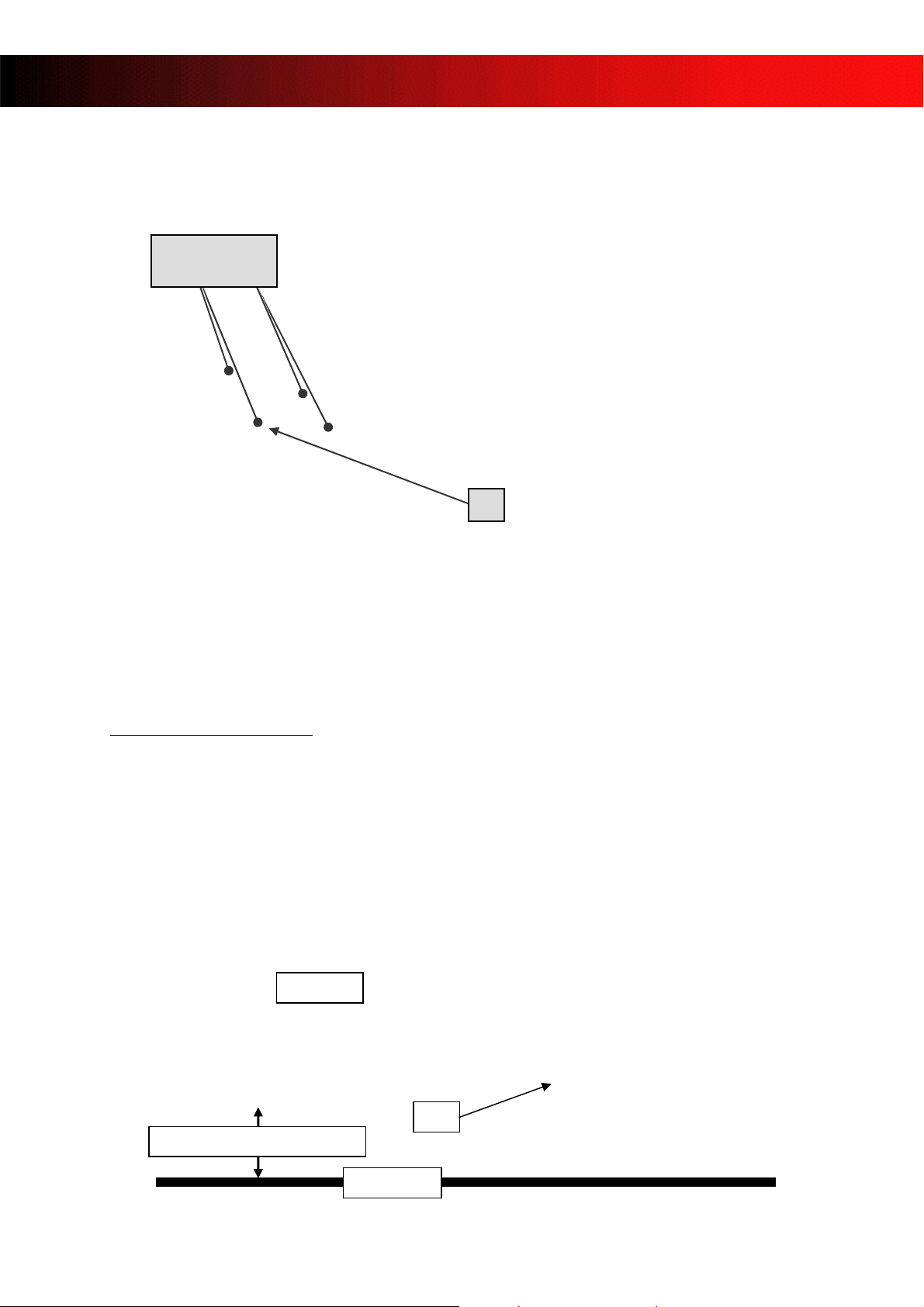
4- ASSEMBLY OF STEERING WHEEL.
¾ Tighten the steering wheel (1) with the 3 screws, on the steering wheel support (2).
¾ Tighten the steering wheel support on the steering column.
Check:
make a quarter of a turn right and left.
STRAIGHT PART
FORWARD
once the steering system is assembled, please check that the steering wheel is free to
1
2
9 A bad assembly or a bad adjustment of the steering system can lead to accidents.
9 Systematically check the tightening of the system and its adjustment.
VERSION : JANUARY 2009 7/26 MAN023.012

MINIKART MANUAL
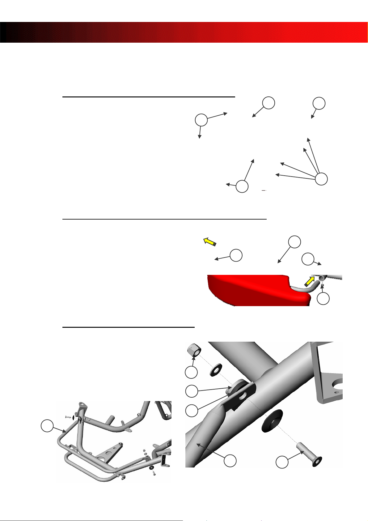
5- ASSEMBLY OF THE FUEL TANK AND THE OVERFLOW BOTTLE.
3
1
2
¾ Insert the fuel tank between the steering column support (1) and the steering column (2)
(see pictures )
¾ Tighten with the fly nut (3)
4
9
5
8
¾ Insert the overflow bottle (4) between the nassau panel supports (5).
¾ Connect the overflow bottle hose (6) to the return (7).
¾ Connect the petrol tank hose (8) to the red plug (9).
NOTE:
- CHECK THE PRESENCE OF THE DIVER UNDER THE RED PLUG (9).
6
7
VERSION : JANUARY 2009 8/26 MAN023.012
MINIKART MANUAL
6-ASSEMBLY OF THE SEAT
4 FIXING
POINTS
1
Measurements given below correspond
to the standard adjustment of the seat,
recommended by SODIKART, for the
MINIKART.
Get the seat supports (1) closer, or
wider, depending on the seat size.
Use the shims of the seat fixing kit to
get a good fit.
¾ The washers of the seat fixing kit comply with CIK/FIA and with your local national
rules.
6-1 GROUND CLEARANCE
SEAT
1Bar
24mm or 6 rear sprockets
GROUND
VERSION : JANUARY 2009 9/26 MAN023.012

MINIKART MANUAL
-2 DISTANCE BETWEEN THE REAR AXLE AND THE MIDDLE OF THE ROUND REAR
6
EDGE OF THE SEAT.
250mm
Measure from the
middle of the
rounded edge
6-3 DISTANCE BETWEEN THE AXIS OF THE LEFT SIDE STUB AXLE FORK AND THE
MIDDLE OF THE REAR ROUNDED EDGE OF THE SEAT.
865mm
VERSION : JANUARY 2009 10/26 MAN023.012
3
3 4 3
1 5 2
MINIKART MANUAL
7 – ASSEMBLY OF THE BODYWORK
7.1 – ASSEMBLY OF THE SIDE POD ON ITS SUPPORT
¾ Position the side pod (1) on its support
(2).
¾ Place the screws (3) through the fixing
holes of the side pod support (2), the
side pod (1), and the washers.
¾ Tighten the parts together with the
screws (3) and the nuts (4).
For the bolting, refer to the spare parts
catalogue
7.2 – ASSEMBLY OF THE SIDE POD SUPPORT ON THE FRAME
¾ Place the side pod support (1) on the
frame (2).
¾ Place the screw (3) through the fixing
hole of the side pod support (1).
¾ Tighten the parts together with the screw
(3) and the nut (4).
For the bolting, refer to the spare parts
catalogue
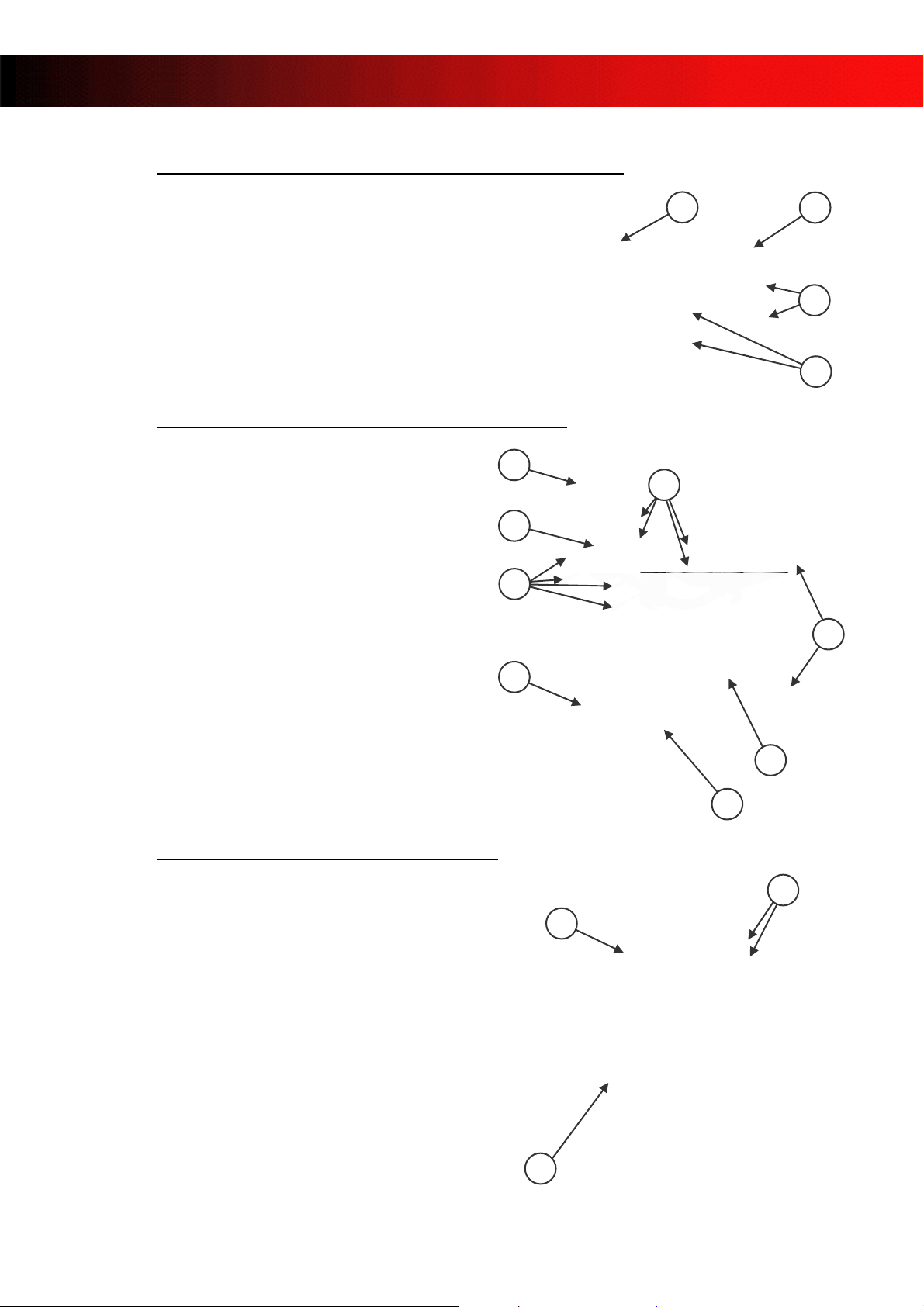
7.3 – ASSEMBLY OF THE FRONT BUMPER
¾ Position the front bumper (1) on the outer
face of the lug (2).
¾ Place the plastic washers (3) between
the front bumper (1) and the lug (2).
¾ Tighten the front bumper (1) with the
screws (4) and the nuts (5).
For the bolting, refer to the spare parts
catalogue
3
1
2
1
4
2
1
4
VERSION : JANUARY 2009 11/26 MAN023.012
1 2
4
2
2 4
MINIKART MANUAL
7.4 – ASSEMBLY OF THE LOWER FLAP ON THE SPOILER
¾ Place the two screws (1) through the
lower flap (2) and the spoiler (3).
¾ Tighten the parts together with the
screws (1) and the nuts (4).
For the bolting, refer to the spare parts
catalogue
7.5 – ASSEMBLY OF THE SPOILER ON THE FRAME
¾ Mount the spoiler fixing kit (1) on the front
bumper (2) and the frame (3) with the
bolting (4).
¾ Tighten the spoiler fixing kit (1).
¾ Place the spoiler (5) between the front
bumper (2) and the frame (3).
¾ Pull down the front bumper (2) on the
spoiler (5)
¾ Put the bridle (6) on the front bumper (2)
and the frame (3), then lock.
For the bolting, refer to the spare parts
catalogue
5
7.6 – ASSEMBLY OF THE NASSEAU PANEL
¾ Position the nasseau panel (1) on the
lower flap (2) and the upper flaps (3).
¾ Draw the 3 drill points on the nasseau
panel (1).
¾ Drill with the Ø6.5mm drill.
¾ Place the nassau panel on its fixations.
Then tighten the parts together with 3
screws and 3 nuts.
For the bolting, refer to the spare parts
catalogue
1
3
1
4
3
2
6
3
VERSION : JANUARY 2009 12/26 MAN023.012

MINIKART MANUAL
8- STARTING YOUR MINIKART
SAFETY INSTRUCTIONS TO THE PILOTS
WARNING
YOUR KART CAN ONLY BE DRIVEN ON A TRACK APPROVED BY CIK/FIA, OR YOUR
LOCAL FEDERATION AND BY A DRIVER WHO IS IN POSSESSION OF A VALID
MEMBERSHIP CARD OF THE GO-KART’S FEDERATION OF HIS OWN COUNTRY.
PILOT PROTECTION
Before going on the track, the pilot must wear the following protections:
• Integral helmet: CIK/FIA approved, fitting the pilot head size, with tightened strap and
closed visor. Refer to CIK/FIA regulations (compulsory).
• Suit: CIK / FIA level 1 or level 2 approved. (compulsory)
• Gloves. (compulsory)
• Neck protection : CIK/FIA approved (compulsory)
• Rib protection: fitting pilot’s size and seat (recommended).
• Rain suit: with water tight fasteners (recommended when necessary).
CHOOSE THOSE EQUIPMENTS WITHIN THE CIK / FIA APPROVED ONES OF THE
ITAKA CATALOGUE
DRIVING IS FORBIDDEN TO ANY PILOT:
¾ Wearing a scarf because of risk with rotating parts.
¾ With long hair coming out of the helmet.
¾ With wide floating clothes.
¾ With health problems, not compatible with high speed driving.
¾ Under the influence of drugs and (or) alcohol.
9 For your safety and the safety of other pilots, strictly follow the above instructions:
not doing so may lead to severe, even fatal injuries.
9 Be aware that some medicines reduce your ability to drive
VERSION : JANUARY 2009 13/26 MAN023.012

MINIKART MANUAL
9- ADJUSTMENT OF THE FRONT
9.1 ADJUSTMENT OF THE FRONT WIDTH
The adjustment of the front width (X) is done with several spacers (one spacer of 17mm, 10mm,
and 5mm for each stub axle.).
17mm
10mm
5mm
The wider the front is widened, the harder the steering is hard, and the narrower the front is
narrows, the easier the steering is easy.
984mm < X < 1048mm
VERSION : JANUARY 2009 14/26 MAN023.012

MINIKART MANUAL
9.2 ADJUSTMENT OF PARALLELISM
1. Lay the kart on a trolley.
2. Place the adjustment tool (1) (refer to the ITAKA
catalogue).
3. Loosen the lock nuts on each tie rod (2).
¾ Attention: on the stub axle side, lock nuts are
right hand; on the steering column side, lock nuts
are left hand.
4. Position the steering wheel in the axis of the kart.
5. Measure A and B with a tape. Adjust the tie rods
until you get A=B with a tie rod length on the right
side 1.5mm bigger than the tie rod length on the
left side.
6. When A=B the parallelism is perfect.
Tighten the 2 lock nuts on each tie rod (2).
7. Remove the adjustment tool (1). Mount the wheels;
mind the direction of rotation indicated on the side of
the tires.
PERFECT
ADJUSTMENT
A=B
A
2
B
1
NOTE:
- Do not forget to tighten the 2 lock nuts on the tie rods; otherwise the
parallelism will be lost in a few minutes.
- Any time you work on the front wheels, check the parallelism. Do the same
after shocks.
9 Never drive with badly tightened wheels: it may lead to severe, even fatal injuries.
9 Make sure that each ball joint penetrates at least 5 threads in the tie rods.
VERSION : JANUARY 2009 15/26 MAN023.012

MINIKART MANUAL
9.3- ADJUSTMENT OF TIE RODS.
VERSION : JANUARY 2009 16/26 MAN023.012

MINIKART MANUAL
10- ADJUSTMENT OF THE REAR
10-1 ADJUSTMENT OF HUBS
1. Lay the kart on a trolley.
2. Loosen the three bolts of each tyre. Then
remove the two wheels.
3. Measure the distance
the hub (3) to the axle edge (2).
4. Loosen the CHC (4) screws to allow the sliding
of the hub on the axle and cotter pin (5).
5. Slide the hub up to the position you wish.
6. Tighten and block the CHC (4) screws.
7. Mount the wheels; mind the direction of
rotation indicated on the side of the tires.
Tighten the bolts and block.
A, from the basis of
AXLE
4
HUB
5
HUB
NOTE:
- A rear tracking width is measured from the outside of the rims (left and right).
- A wider rear tracking width tends to increase sliding. Too narrow a rear tracking
width may lead to a bumpy chassis.
9 Badly tightened wheels may lead to severe, even fatal injuries.
9 Check the cotter pin is correctly positioned.
9 Never position the hubs beyond the maximum allowed width: it may lead to severe or
even fatal injuries.
3
1
A
2
VERSION : JANUARY 2009 17/26 MAN023.012

MINIKART MANUAL
10-2 POSITION OF REAR AXLE
¾ A large ground clearance means more grip.
¾ A low ground clearance means more sliding.
In most conditions, the correct axle position is the low ground clearance one.
This corresponds to a high position of the axle, relative to the frame.
VERSION : JANUARY 2009 18/26 MAN023.012

MINIKART MANUAL
11- ADJUSTMENT OF SEAT
POSITION OF THE SEAT
The position of the center of gravity has also a key influence on the behavior of the kart.
One can monitor this center of gravity by changing the position of the seat.
You will find the best position of the seat, adapted to your size and weight, by trial-and error.
We recommend you to bear in mind the following:
SEAT MOVED FORWARD:
Gives more grip on the front wheels; more sliding of the rear wheels.
SEAT MOVED BACKWARDS:
Less grip on the front wheels; more grip on the rear wheels.
SEAT LOWER:
Less grip (front and rear wheels); to try on very high grip conditions.
SEAT HIGHER:
Increases the grip; to be tried in wet conditions.
VERSION : JANUARY 2009 19/26 MAN023.012
MINIKART MANUAL
12- TYRES
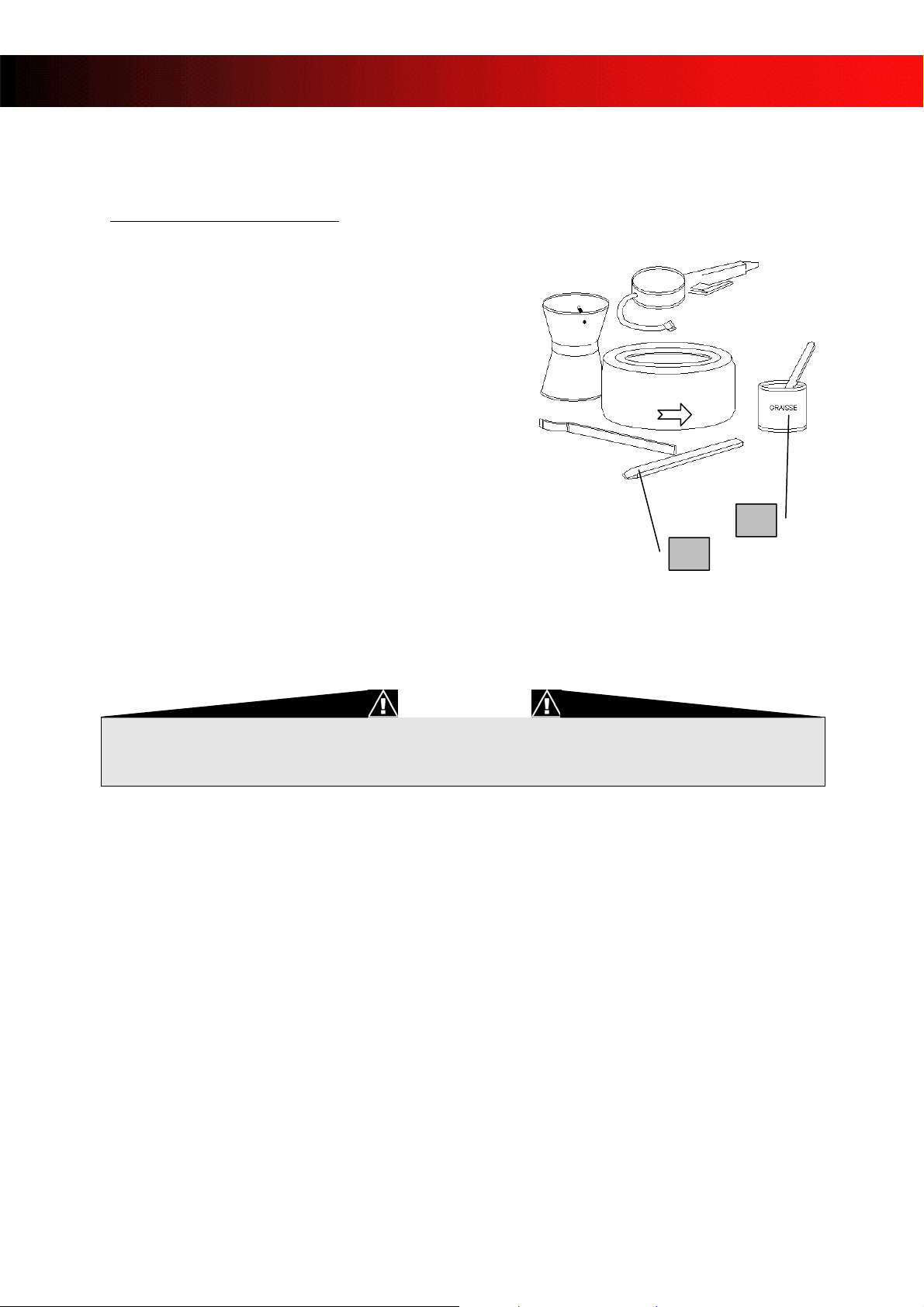
12-1 CHANGING THE TYRES
1. Lay the kart on a trolley.
2. Lay the wheel on the tire removal tool
(OU942.002)
3. Once the edges of the tire are separated
from the rim on both sides, remove the tire
with the tool (2).
4. Put grease (3) (LU823.003) on the edges of
the new tire.
5. Install the tire on the rim; mind the
direction of rotation.
6. Inflate to let the tire get its position on the
rim.
7. Adjust the pressure according to table next
page, with the manometer (OU943.002).
9 Check the direction of rotation on the sides of the tire.
9 Never inflate above 4 bars: there is a risk of severe injury due to potential failure of
the rim.
:
Rotating direction
2
3
VERSION : JANUARY 2009 20/26 MAN023.012

2
MINIKART MANUAL
13- HYDRAULIC BRAKE
13.1 CHANGING BRAKE PADS
¾ Remove the safety pin (1).
¾ Remove the worn pads (2). Then insert
the new ones.
9 The brake system is a key safety item of the kart. Regularly check all its components.
In case of doubt, do not drive before fixing the problem.
9 Bad maintenance of the brakes can lead to severe, even fatal injuries.
9 Never repair a break system on your own; return it to SODIKART through your local
dealer.
1
14- BLEEDING THE BRAKE SYSTEM
1- Take a fuel hose and put it on the
bleed screw (3).
2- Press the brake pedal (1) and
maintain the pressure.
3- Open the bleed screw (3); liquid and
air bubbles come out.
4- Close the bleed screw (3).
5- Release the brake pedal.
6- Fill the brake liquid tank with DOT 4
only.
7- Make sure the maximum level is (2).
Repeat operations 3 to 8, until the brake
pedal becomes hard.
1
3
NOTE:
- The brake system must be regularly checked: level of brake fluid, cover of the
brake fluid tank, state of screws and bolts.
- If the brake fluid becomes black, bleed and change it.
- Bleed and change the brake fluid after each brake pads replacement.
9 Use brake liquid DOT 4 only.
9 Don’t use DOT 5, it can damage the seal and cause a lost of braking p ower.
2
VERSION : JANUARY 2009 21/26 MAN023.012

MINIKART MANUAL
14- MECHANICAL BRAKE
14.1 POINTS TO CHECK:
1. Brake cables: They must be in perfect
state and never have edge points.
Change damaged cables.
2. Brake calliper (1): It must be correctly
tightened on its support (2). The support
(2) must also be correctly tightened on the
chassis.
3. Brake pads (4) must be correctly positioned
into brake calliper (1) and assemble the 2
screws (5). Do not forget to reinstall the
return spring.
4. Brake disk (6): Make sure the brake disk
support is assembled with a cotter pin and
correctly tighten on the rear axle (7).
5. Make sure the brake disk is correctly
tightened on brake disk support.
7
4
1
2 3
5
NOTE:
- The brake system must be checked regularly: state of screws and bolts, fixation
of brake pads, centering and tightening of brake disk, and mechanical link
between pedal and master cylinder.
9 The brake system is a key safety item of the kart. Regularly check all its components.
In case of doubt, do not drive before fixing the problem.
9 Bad maintenance of the brakes can lead to severe, even fatal injuries.
9 Use spare parts of SODIKART origin.
6
VERSION : JANUARY 2009 22/26 MAN023.012

MINIKART MANUAL
14.2 BRAKE PADS REPLACEMENT
1. Remove the brake calliper (1) of
its support (2).
2. Remove the 4 screws (3) with
springs.
3. Remove the pads; insert the new
ones (4).
4. Place the 4 screws (3) with
springs with drop of glue
(Loctite 221 purple, ref:
LU861.002).
5. Loosen the bolt (5).
6. Tighten the screw (6) to place
the pads against brake disk.
7. Then loosen by one and a
quarter of a turn to get the gap
between the pads and the disk.
8. Tighten the bolt (5).
NOTE:
- The adjustment of the gap between the disk and the pads is done with the screw (6).
The standard gap is 1mm.
4
3
1
5
6
2
VERSION : JANUARY 2009 23/26 MAN023.012

MINIKART MANUAL
15- CLEANING THE CHASSIS
• The cleaning of the chassis and its components is to be done with a special cleaning product
(refer to the ITAKA catalogue). Do not use the product on brake pads and brake calipers.
Avoid products which are not recommended in the ITAKA catalogue. They may be too
aggressive and damage painted and coated areas, plastic parts as well as gaskets.
1. Protect the break calipers and the brake disk with a dry piece of cloth.
2. Spray the whole kart with the cleaning product, and let it act for 30 seconds.
3. Wipe the frame and the components with a dry cloth.
NOTE:
- Clean your kart on a regular basis: it is a good way to check it and detect
damages, if any.
9 Spray cleaning product on brake pads or brake caliper may reduce the braking abili ty
partially or totally, and can lead to a serious accident.
9 If any doubt, drive carefully the first laps, and test the brakes until the braking
ability becomes normal.
VERSION : JANUARY 2009 24/26 MAN023.012

MINIKART MANUAL
16- MAINTENANCE PLAN
Screws and bolts (general):
¾ Before each use, check the state of the screws and bolts. Pay a special attention to the
ones directly linked to the safety of the kart :
• Stub axle screw.
• Steering tie rods ball joint screws.
• Front and rear wheels bolts.
• Rear wheel hub screws.
• Engine support screws.
• Seat screws.
¾ Damaged screws and bolts have to be changed.
Steering:
¾ Check the tightening torque of the steering column support.
¾ Check the tightening torque of the stub axle screw.
¾ Check the parallelism.
Body work:
¾ Check the various body work components: make sure they are free of damages such as
cracks, likely to propagate when driving.
¾ Check the fixings of the body work components: make sure they are not loose or damaged.
¾ When replacing a body work component, make sure the screws and bolts are put in the right
direction (as original).
Tires:
¾ Pay a special attention to the assembly of the tires.
¾ Make sure the direction of rotation is correct, as indicated on the sides of the tires.
¾ Check the wear of the tires. The wear indicator should always be visible
¾ Damaged tires must be changed.
¾ Check the pressures before driving, according to recommendations (table page 24).
Brake system
¾ Check the brake system before going on the track.
¾ Ensure the system is tight by pressing the brake pedal: once the pads are in touch with the
disk, the pedal should not move any further.
.
VERSION : JANUARY 2009 25/26 MAN023.012

MINIKART MANUAL
17- TROUBLE SHOOTING.
Brakes do not work:
1. Is the pedal working correctly (not blocked)?
2. Are the break pads worn out?
3. Is the caliper correctly tightened on its support?
The brake pads permanently touch the disk:
1. Is the brake fluid old or black?
2. Is the brake disk correctly aligned?
3. Is the caliper well tightened on its support?
4. Is the brake pedal free to rotate around its axis?
5. Is the brake pads gap correct?
The steering is hard.
1. Are the screws of the stub axles tightened with the right torque?
2. Is the caster too high?
The steering of the kart is not precise.
1. Are the steering tie rods bent?
2. Is the plastic steering column support well tightened?
3. Is the steering column support well tightened on the frame?
The kart tends to go to the right or to the left.
1. Is the parallelism OK?
2. Are the pressures of the tires OK (left vs. right)?
3. Are the tires diameter equal (middle and sides)?
4. Are the two block nuts of the steering tie rods well tightened?
5. Are the tie rods bent?
VERSION : JANUARY 2009 26/26 MAN023.012
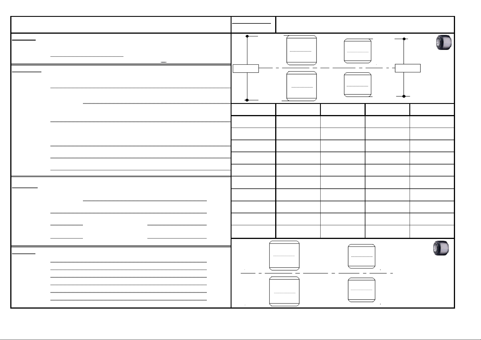
TRACK: DATE: TRIAL TIMES
P
S
Heigh
Di
M
Axl
Stiff
ENGINE
Adj
Exh
Length
PILOT: TRIAL: TIME:
TRACK:
State of the track: °C
CHASSIS:
Stub axle height :
Caster and camber :
Tyre type: Diameter:
PRESSURE
START
arallelism :
eat position :
t : Dist- axle :
asses :
e type :
eners :
:
carburator type :
usments :
aust type :
:
Gear ratio : Chain length :
NOTES:
st- fork :
1
2
3
4
5
6
7
8
9
10
Partial 1 Partial 2 Partial 3LAP
Partial 4
PRESSURE
ARRIVAL
 Loading...