

Page 1
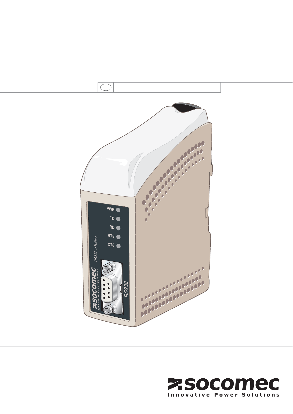
CONVERTER
RS232 <=> RS485
Operating instructions
GB
MAKE YOUR BUSINESS SAFE
Page 2

SOCOMEC - Ref. : 874 666 B GB
Converter
2
GENERAL INFORMATION __________________________________3
Safety __________________________________________________3
Maintenance_____________________________________________3
Introduction _____________________________________________3
APPROVALS AND CONFORMITY____________________________4
Declaration of conformity __________________________________5
SPECIFICATIONS __________________________________________6
Environmental conditions and type tests _____________________6
Main features ____________________________________________8
INSTALLATION ____________________________________________9
Mounting/removal ________________________________________9
Connections____________________________________________10
LED Indicators __________________________________________10
DIP switch settings ______________________________________11
FUNCTIONAL DESCRIPTION ______________________________13
Field of application ______________________________________13
APPLICATION EXAMPLE __________________________________15
Contents
GB
Page 3
IMPORTANT NOTE TO BE READ BEFORE INSTALLATION
Safety
Check that your application meets the equipment's
technical specifications for operation.
Dangerously high voltage levels can be produced when
this equipment is connected to the power supply or TNV
circuits.
To prevent electric shocks, the equipment must be
disconnected from the power supply and all other
electrical connections.
You are recommended to ground yourself to avoid
electrostatic discharge (ESD) damage to internal
components (e.g.: wear electrostatic bracelets.
BEFORE INSTALLATION
This equipment is designed for industrial use. It must
be installed in an equipment room where access is
strictly restricted to authorised personnel.
The power supply must have adequate electrical
protection and it must be possible to disconnect the
equipment manually.
Ensure that the installation complies with current national
regulations.
This equipment uses convection cooling. Ensure to leave
sufficient space around the equipment to enable proper
airflow (refer to the chapter on installation).
Maintenance
No maintenance is required provided that the equipment
is used under the conditions specified.
Introduction
The RS232<=>RS485 converter has been designed to
convert signals between an RS232/V.24 interface and
an RS485 interface. This equipment is often used in
multidrop applications, connected to a PC, automation
devices and other industrial equipment.
In 2 wire half-duplex mode (RS485), the converter can
automatically control the direction of the transmission
on the bus by data flow. In this case, the converter will
automatically determine the bus reversal depending on
the direction of the data transmitted.
In this way, the converter can also be used to connect
equipment which has no handshaking signal.
The maximum data transmission rate is 115.2 Kbit/s.
3
SOCOMEC - Ref. : 874 666 B GB
RS232 <=> RS485
GENERAL INFORMATION
Converter
Read the manual carefully and ensure you have
fully understood its contents before operating
this equipment for the first time.
This equipment must only be installed
by qualified technicians.
Page 4
RS232 <=> RS485
Converter
4
SOCOMEC - Ref. : 874 666 B GB
RS232 <=> RS485
APPROVALS AND CONFORMITY
Type Accreditation/
Compliance
EMC standard EN 61000-6-2 Immunity for industrial environments
EN 55024 Immunity for IT equipment
EN 61000-6-3 Emission standard for residential environments
FCC part 15 Class B
EN 50121-4 Railway applications: immunity for signalling and telecommunications apparatus.
IEC 62236-4 Railway applications: immunity for signalling and telecommunications apparatus.
Safety EN 60950 IT Equipment
Page 5
5
SOCOMEC - Ref. : 874 666 B GB
RS232 <=> RS485
Converter
APPROVALS AND CONFORMITY
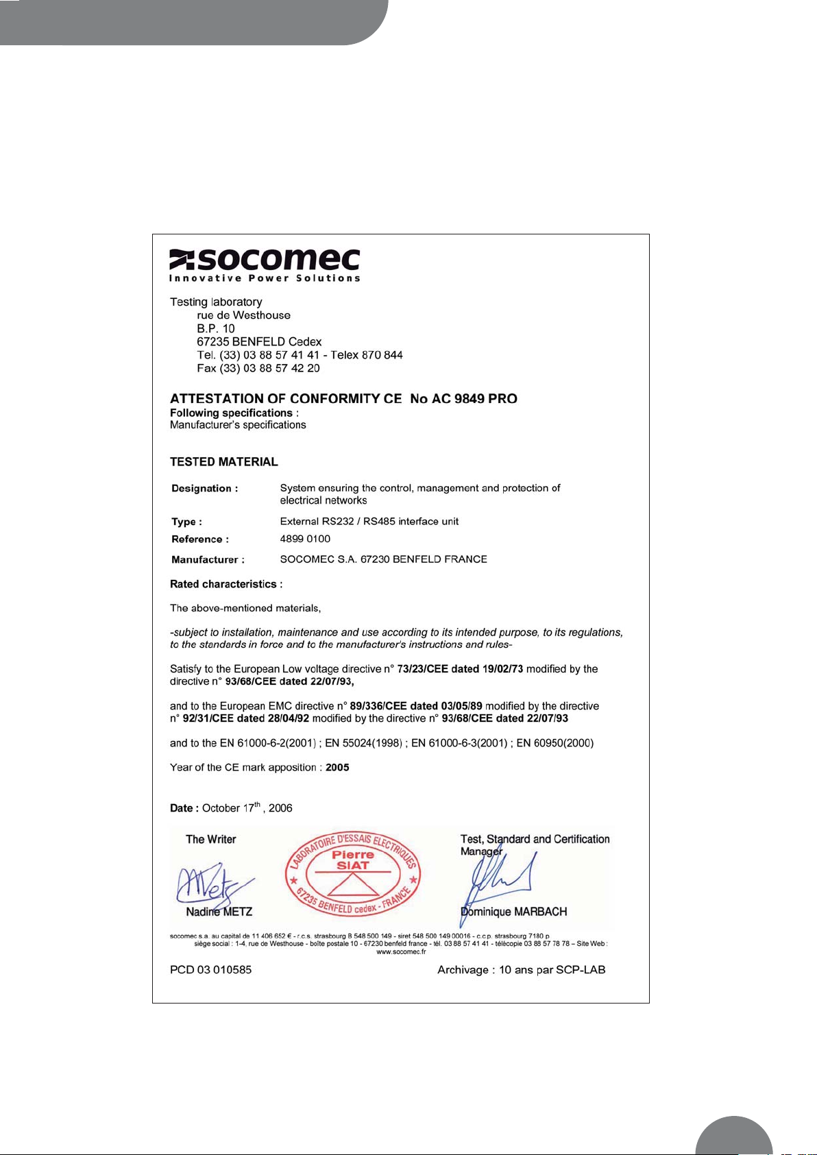
Declaration of conformity
INTER_036_B_GB
Page 6
Environmental conditions and type tests
RS232 <=> RS485
SPECIFICATIONS
Converter
6
SOCOMEC - Ref. : 874 666 B GB
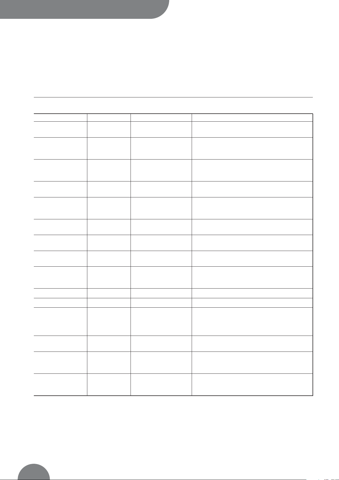
Phenomenon Standards Description Level
EN 61000-4-2 Unit contact ± 6 kV
Unit air ± 8 kV
IEC 61000-4-3 Unit 10 V/m 80% AM (1 kHz), 80 – 1 000 MHz
20 V/m 80% AM (1 kHz), 800 – 960 MHz
20 V/m 80% AM (1 kHz), 1 400 – 2 000 MHz
ENV 50204 Unit 20V/m modulated pulse 200 Hz, 900 ± 5 Mhz
EN 61000-4-4 Signal ports ± 2 kV
Supply ports ± 2 kV
EN 61000-4-5 ± 2 kV line to earth, ± 2 kV line to line
Balanced signal port ± 2 kV line to earth, ± 1 kV line to line
Supply ports ± 2 kV line to earth, ± 2 kV line to line
EN 61000-4-6 Signal port 10 V 80% AM (1 kHz), 0.15 – 80 MHz
Supply port 10 V 80% AM (1 kHz), 0.15 – 80 MHz
EN 61000-4-8 Unit 100 A/m, 50 Hz, 16.7 Hz & 0 Hz
EN 61000-4-9 Unit 300 A/m, 6.4 / 16 pulse
EN 61000-4-11 AC supply port 10 & 5000 ms interruption
30% 10 & 500 ms reduction
60% 100 & 1000 ms reduction
Power frequency 50 hz EN 61000-4-16 Signal port 100 V 50 Hz
Power frequency 50 hz SS 436 15 03 Signal port 250 V 50 Hz
EN 61000-4-29 DC supply port 10 & 100 ms interruption
10 ms, 30% reduction
10 ms, 60% reduction
+20% above & –20% below rated voltage
Radiated emission EN 55022 Unit Class B
FCC part 15 Class B
EN 55022 AC supply port Class B
FCC part 15 AC supply port Class B
EN 55022 DC supply port Class B
Dielectric strength 2 Kv rms 50Hz 1 Min.
3 Kv rms 50Hz 1 Min.
2 Kv rms 50 Hz 1 Min. (@ rated voltage<60V)
ESD Electrostatic
discharge
Burst
(fast transient)
Surge
(lightning)
HF current injection
Power frequency
magnetic field
Pulse magnetic field
Voltage
variation and dips
Voltage
variation and dips
Signal ports to all other
Supply ports to all
other
Conducted emission
Unbalanced signal port
Modulated
electromagnetic
radiation (AM)
Electromagnetic
radiation 900 Mhz
Page 7

Environmental conditions and type tests
ENVIRONMENTAL
RS232 <=> RS485 Converter
SPECIFICATIONS
7
SOCOMEC - Ref. : 874 666 B GB
Phenomenon Standards Description Level
Temperature Operating - 40 to +70°C
Storage - 40 to +70°C
Humidity Operating 5 to 95% relative humidity
Storage 5 to 95% relative humidity
Altitude Operating 2000 m / 70 kPa
MTBF Operating 10 years
Vibration IEC 60068-2-6 Operating 7.5 mm, 5 – 8 Hz
2 g, 8 – 500 Hz
Shock IEC 60068-2-27 Operating 15 g, 11 ms
ENCLOSURE
Phenomenon Standards Description Level
Unit UL 94 PC / ABS Flammability class V-1
Dimensions LxHxD 35 x 121 x 119 mm
Weight 0.19 kg
Protection index IEC 529 Unit IP 21
Cooling Convection
Mounting Horizontal on 35 mm DIN-Rail
Page 8

Main features
RS485
RS232 <=> RS485
SPECIFICATIONS
Converter
8
SOCOMEC - Ref. : 874 666 B GB
Electrical specifications RS485
Speed 1200 bit/s – 115.2 kbit/s
Data format 7 or 8 bits, Odd, Even or None parity, 1 or 2 stop bit
Connection Detachable screw terminal
Conductor size 0.2 – 2.5 mm2(AWG 24-12)
Transmission range In accordance with EIA RS485
≤ 1200 m, depending on cable type and speed
Configuration 120 Ω termination
and 680 Ω fail-safe biasing by DIP-switch
Protection Installation Fault Tolerant (up to ± 60 V)
RS232
Electrical specification RS232-C
Speed 1200 bit/s – 115.2 kbit/s
Data format 7 or 8 bits, Odd, Even or None parity, 1 or 2 stop bit
Connection 9 pin D-sub female DCE
Transmission range 15 m
INPUT SUPPLY
RS232 <=> RS485
Rated voltage 95 to 240 VAC
110 to 250 VDC
Operating voltage 85.5 to 264 VAC
88 to 300 VDC
Rated current 21 mA @ 95 VAC
10 mA @ 110 VDC
Rated frequency 48 – 62 Hz / DC
Polarity Independent polarity
Connection Detachable screw terminal
Conductor size 0.2 – 2.5 mm2(AWG 24-12)
Page 9

9
SOCOMEC - Ref. : 874 666 B GB
RS232 <=> RS485
INSTALLATION
Converter
Mounting /removal
This equipment must be mounted on a 35 mm DIN-rail,
mounted horizontally to a wall or inside an apparatus
cabinet.
Snap-on mounting (see figure).
This equipment uses convection cooling. To optimise the
flow of air around the unit, leave sufficient space around
the equipment and observe the following instructions:
Recommended space around unit:
- above/below: 25 mm,
- right/left: 10 mm.
It is essential to leave this space around the unit to
ensure correct operation across the full range
of temperatures and service life.
COOLING
Press down on the black clip on the top of the unit.
(See figure)
REMOVAL
* Allow the correct space (Right/Left) to ensure correct
operation across the full range of temperatures.
INTER_037_AINTER_038_BINTER_039_A
CLICK !
10 mm *
(0.4 inches)
25 mm
25 mm
Page 10

Pos. Description Product marking
1 AC: Neutral
DC: Voltage – N/–
2 AC: Line
DC:Voltage + L/+
LED Indicators
RS232 <=> RS485
INSTALLATION
Converter
10
SOCOMEC - Ref. : 874 666 B GB
Connections
>
RS485
>
RS232 (DCE)
S2 DIP-switch
(see details page 11)
S1 DIP-switch under cap
(for details see page 11)
Pos. Direction Description
3 Input / Output T-: Line RS485
4 Input / Output T+: Line RS485
LED Indicators
(see details below)
Pos. Direction Description
1–
2 Output Received Data (RD)
3 Input Transmitted Data (TD)
4–
5 – Earth (Signal Ground)
6 Output Data Set Ready (DSR)
7 Input Request To Send (RTS)
8 Output Clear To Send (CTS)
9 –
>
Input supply
RAILWAY INSTALLATION CLOSE TO THE RAILS
For a cable located inside 3 m boundary and connected
to this port, the use of a shielded cable is recommended,
to minimise the risk of interference. The cable shield
should be properly connected (360°) to an earthing point
within 1 m of this port. This earthing point should have
a low impedance connection to the conductive enclosure
of the apparatus cabinet, or similar, if the unit is built-in.
This conductive enclosure should be connected to the
earthing system of the installation and may be directly
connected to the protective earth.
LED Status Description
PWR On Operating
Off Not operating
TD On Transmitted data: data received from local RS232 port
Off No data transmitted
RD On Received data: data sent to the RS232 port
Off No data received
RTS On RTS signal active on RS232 interface
Off RTS inactive
CTS On CTS signal active on RS232 interface
Off CTS inactive
INTER_008_B
Page 11

RS232 <=> RS485 Converter
INSTALLATION
11
SOCOMEC - Ref. : 874 666 B GB
DIP switch settings
In “RTS control” and “Transmitter always active” modes,
the data flow configuration and data format selection
switches are not effective.
To prevent electric shocks, the equipment
must be disconnected from the power
supply and all other electrical connections.
S1
ON
12345678
1200 bit/sS1
ON
12345678
2400 bit/sS1
ON
12345678
4800 bit/sS1
ON
12345678
9600 bit/sS1
ON
12345678
19.2 kbit/sS1
ON
12345678
38.4 kbit/sS1
ON
12345678
57.6 kbit/sS1
ON
12345678
115.2 kbit/sS1
>
Data rate configuration
>
Data Format Selection
>
RTS control or data flow
ON
12345678
9 bit format*S1
ON
12345678
10 bit format*S1
ON
12345678
11 bit format*S1
ON
12345678
12 bit format*S1
ON
12345678
Data flowS1
ON
12345678
RTS controlS1
ON
12345678
Transmitter always active
S1
* Refer to the reference table to determine the number of bits.
Reference table for data format selection (number of bits)
7 Bits • • • •
8 Bits • • • •
No parity • • • •
Parity • • • •
1 stop bit • • • •
2 stop bits • • • •
Number of bits 9 10 10 10 11 11 11 12
S1
INTER_005_A
Page 12

DIP-switch settings
S2
RS232 <=> RS485
INSTALLATION
Converter
12
SOCOMEC - Ref. : 874 666 B GB
Note: DIP-switch configurations are only effective after the equipment
has been switched off and on again.
>
On lower panel, RS485 termination
No termination or fail-safe
ON
1234
Termination with fail-safe
ON
1234
S2
FACTORY SETTINGS
ON
12345678
Speed: 9600 bit/s
Data format: 10 bits
Bus format: 2 wire
Termination and fail-safe on
Note: SW1: 8 not used.
ON
1234
S1
S2
INTER_006_B
Page 13

13
SOCOMEC - Ref. : 874 666 B GB
RS232 <=> RS485
FUNCTIONAL DESCRIPTION
Converter
When the converter is configured to data flow reversal
mode, the transmitter is activated by transmitted data
on TD from the RS232.
The transmitter stays active for a period equal to one
character time. The reversal time is determined by the
transmission format: speed and number of bits. If there
is more data to be transmitted after the reversal time has
expired, the transmitter will stay active for an additional
one character time.
In RTS reversal mode, the transmitter is activated by the
RTS signal. In this case, the DIP-switches determining
the speed and number of bits are inactive. The LED indicators are controlled by the data signals. The fail-safe
terminations will protect the receivers when there is no
transmission by forcing them to OFF status. (>0.2 Volts).
The RS485 standard is designed for multidrop applications.
The system network installed must form a bus structure
(see diagram). Star shaped networks are not permitted.
To correctly install a RS485 system network, it is essential that terminations are fitted at the corresponding
points. Terminations must be fitted to the receiver on
the master unit and the final bus slave unit.
The diagram opposite shows a correct RS485 connection.
Field of application
Note: T+/T– are not standard. Connection problems
may be resolved by switching the + and – wires if the
equipment does not operate correctly.
INTER_007_A_GB
1200 meters max
T+
T–
T+ T– T+ T– T+ T–
= Termination
0.3 meters max
32 connections max
Page 14

Field of application
RS232 <=> RS485
FUNCTIONAL DESCRIPTION
Converter
14
SOCOMEC - Ref. : 874 666 B GB
LINE CONNECTION
RECOMMENDATIONS FOR USE
Follow the recommendations for use given below to
ensure the equipment operates at full performance and
to fulfil the terms of the warranty.
• This unit must not be operated with the caps open or
removed.
• Do not attempt to dismantle the unit
• There are no serviceable parts inside
• Do not drop, knock, or shake the unit: rough handling
or use beyond the recommendations may cause
damage to internal circuitry.
• Do not clean the unit using harsh chemicals, cleaning
agents or strong detergents.
• Do not paint the unit: paint can block the vents and
affect correct operation.
• Do not expose the unit to any type of liquid (rain, drinks,
etc.) as the unit is not waterproof. Keep the unit within
specified humidity levels
• Do not use or store the unit in dusty or dirty areas:
some mechanical components or connectors may be
damaged.
RS485
Equipment
Transmitter/
Receiver
Transmitter/
Receiver
Twisted pairs
T+/R+ T+/R+
T–/R– T–/R–
3
4
RS232 / RS485
Converter
>
2 wires
INTER_040_A
Page 15
15
SOCOMEC - Ref. : 874 666 B GB
RS232 <=> RS485
APPLICATION EXAMPLE
Converter
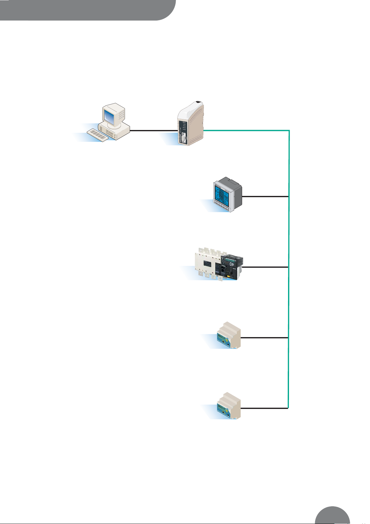
INTER_041_B
RS232 RS232 <=> RS485
PC
RS485
Diris A40
ATyS 6m
Countis CI
RS485
RS485
RS485
Countis CI
Page 16

SOCOMEC - Ref 874 666 B GB - 03/07
INTER_043_B / QUAT NOT 3i
This document is not a contract. SOCOMEC reserves the right to modify features without prior notice in view of continued improvement.
HEAD OFFICE
SOCOMEC GROUP
S.A. capital
11 014 300
€
R.C. Strasbourg 548500 149 B
1, Rue de Westhouse - B.P. 60010 - F-67235 Benfeld Cedex - FRANCE
INTERNATIONAL
SALES DEPARTMENT
SOCOMEC
1, rue de Westhouse - B.P. 60010
F - 67235 Benfeld Cedex - FRANCE
Tél. +33 (0)3 88 57 41 41 - Fax +33 (0)3 88 74 08 00
scp.vex@socomec.com
www.socomec.com
 Loading...