


MODULYS Green Power
From 20 to 240 kVA
Installations- und bedienungsanleitung
DE
Installation and operating manual
GB
Manual de instalación y uso
ES
Manuel d’installation et d’utilisation
FR
Manuale di installazione e uso
IT
Installatie– en bedieningshandleiding
NL
Dokumentacja Techniczno-Ruchowa
PL
Manual de instalação e funcionamento
PT
Manual de instalare şi utilizare
RO
Руководство по установке и эксплуатации
RU
Navodila za priključitev in uporabo
SI

2
MODULYS Green Power - Ref.: IOMMODGPXX01-GB 00
This SOCOMEC UPS continuous power system is guaranteed against any manufacturing and material defects.
The period of validity of the warranty is 12 (twelve) months from the date of commissioning, if said activation is carried out by
SOCOMEC UPS personnel or personnel from a support centre authorised by SOCOMEC UPS, and not however more than 15
(fifteen) months from the date of shipment by SOCOMEC UPS.
The warranty is recognized within national territory. If the UPS is exported out of national territory, the warranty shall be limited to the
cover of the parts used to repair the fault.
The warranty is valid ex-works and covers labour and parts used to repair the fault.
The warranty shall not apply in the following cases:
• Failures due to fortuitous circumstances or force majeure (lightning, floods, etc.);
• Failures due to negligence or improper use (use out of tolerance: temperature, humidity, ventilation, electric power supply, applied
load, batteries);
• Insufficient or inadequate maintenance;
• Attempted maintenance, repairs or modifications not carried out by SOCOMEC UPS personnel or personnel from a support centre
authorised by SOCOMEC UPS.
• If the battery has not been recharged in accordance with the terms indicated on the packaging and in the manual, in cases of
extended storage or UPS inactivity.
SOCOMEC UPS may, at its own discretion, opt for the repair of the product or for the replacement of the faulty or defective parts
with new parts or with used parts that are equivalent to new parts with regard to functions and performance.
Defective or faulty parts replaced free of charge are to be put at the disposal of SOCOMEC UPS who becomes the sole owner.
Replacements or repairs of parts and any modifications to the product during the warranty period cannot extend the duration of
the warranty.
In no case will SOCOMEC UPS be responsible for damages (including, without limitations, damage for loss of earnings, interruption
of activity, loss of information or other economic losses) deriving from the use of the product.
The present conditions are subject to Italian law. Any dispute falls under the province of the Court of Vicenza.
CERTIFICATE AND CONDITIONS OF WARRANTY
SOCOMEC UPS retains the full and exclusive ownership rights over this document. Only a personal right to utilize the document for
the application indicated by SOCOMEC UPS is granted to the recipient of such document. All reproduction, modification, dissemination of this document whether in part or whole and by any manner are expressly prohibited except upon Socomec’s express
prior written consent.
This document is not a specification. SOCOMEC UPS reserves the right to make any changes to data without prior notice.

3
MODULYS Green Power - Ref.: IOMMODGPXX01-GB 00
X. TITRE
ENGLISH
SUMMARY
ENGLISH
1. SAFETY STANDARD . . . . . . . . . . . . . . . . . . . . . . . . . . . . . . . . . . . . . . . . . . . . . . . . . . . . . . . 4
1.1. Important . . . . . . . . . . . . . . . . . . . . . . . . . . . . . . . . . . . . . . . . . . . . . . . . . . . . . 4
1.2. Description of the symbols used on the labels applied to the unit . . . . . . . . . . . 5
1.3. Back-feed protection . . . . . . . . . . . . . . . . . . . . . . . . . . . . . . . . . . . . . . . . . . . . 5
2. REQUISITES . . . . . . . . . . . . . . . . . . . . . . . . . . . . . . . . . . . . . . . . . . . . . . . . . . . . . . . . . . . . . 6
2.1. Environmental requisites.. . . . . . . . . . . . . . . . . . . . . . . . . . . . . . . . . . . . . . . . . . 6
2.2. Electrical requisites. . . . . . . . . . . . . . . . . . . . . . . . . . . . . . . . . . . . . . . . . . . . . . 7
3. UNPACKING . . . . . . . . . . . . . . . . . . . . . . . . . . . . . . . . . . . . . . . . . . . . . . . . . . . . . . . . . . . . . 8
3.1. Before Installation . . . . . . . . . . . . . . . . . . . . . . . . . . . . . . . . . . . . . . . . . . . . . . . 8
3.2. Package Inspections . . . . . . . . . . . . . . . . . . . . . . . . . . . . . . . . . . . . . . . . . . . . . 8
3.3. Storing Conditions for Delayed Installation . . . . . . . . . . . . . . . . . . . . . . . . . . . . 8
3.4. Unpacking . . . . . . . . . . . . . . . . . . . . . . . . . . . . . . . . . . . . . . . . . . . . . . . . . . . . 9
3.5. Installation Environment and Position . . . . . . . . . . . . . . . . . . . . . . . . . . . . . . . 10
4. FRONT AND REAR VIEWS . . . . . . . . . . . . . . . . . . . . . . . . . . . . . . . . . . . . . . . . . . . . . . . . . 11
5. CONNECTIONS . . . . . . . . . . . . . . . . . . . . . . . . . . . . . . . . . . . . . . . . . . . . . . . . . . . . . . . . . 12
5.1. Mains and Aux Mains connected separately . . . . . . . . . . . . . . . . . . . . . . . . . . 12
5.2. Mains and Aux Mains connected in common . . . . . . . . . . . . . . . . . . . . . . . . . 12
5.3. External battery cabinet connection . . . . . . . . . . . . . . . . . . . . . . . . . . . . . . . . 13
5.4. Parallel connection . . . . . . . . . . . . . . . . . . . . . . . . . . . . . . . . . . . . . . . . . . . . . 14
6. POWER MODULE INSTALLATION . . . . . . . . . . . . . . . . . . . . . . . . . . . . . . . . . . . . . . . . . . . 16
6.1. Installation . . . . . . . . . . . . . . . . . . . . . . . . . . . . . . . . . . . . . . . . . . . . . . . . . . . . 16
6.2. Status LED Indicators for Power Module . . . . . . . . . . . . . . . . . . . . . . . . . . . . 17
7. MIMIC PANEL . . . . . . . . . . . . . . . . . . . . . . . . . . . . . . . . . . . . . . . . . . . . . . . . . . . . . . . . . . . 18
7.1. Mimic panel . . . . . . . . . . . . . . . . . . . . . . . . . . . . . . . . . . . . . . . . . . . . . . . . . . 18
7.2. Meaning of ideograms . . . . . . . . . . . . . . . . . . . . . . . . . . . . . . . . . . . . . . . . . . 19
7.3. Meaning of the luminous bar. . . . . . . . . . . . . . . . . . . . . . . . . . . . . . . . . . . . . . 19
7.4. LCD display hierachy . . . . . . . . . . . . . . . . . . . . . . . . . . . . . . . . . . . . . . . . . . . 20
8. OPERATING PROCEDURES . . . . . . . . . . . . . . . . . . . . . . . . . . . . . . . . . . . . . . . . . . . . . . . . 21
8.1. On line operations . . . . . . . . . . . . . . . . . . . . . . . . . . . . . . . . . . . . . . . . . . . . . . 21
8.2. Operation in high efficiency "Eco-mode" . . . . . . . . . . . . . . . . . . . . . . . . . . . . . 21
8.3. Converter mode . . . . . . . . . . . . . . . . . . . . . . . . . . . . . . . . . . . . . . . . . . . . . . . 21
8.4. Operation with manual maintenance bypass . . . . . . . . . . . . . . . . . . . . . . . . . . 21
8.5. Commissioning . . . . . . . . . . . . . . . . . . . . . . . . . . . . . . . . . . . . . . . . . . . . . . . . 22
8.6. Single Unit (up to 120 kVA) . . . . . . . . . . . . . . . . . . . . . . . . . . . . . . . . . . . . . . . 22
8.7. Two units in parallel (up to 240 kVA) . . . . . . . . . . . . . . . . . . . . . . . . . . . . . . . . 24
9. POWER MODULE REPLACEMENT . . . . . . . . . . . . . . . . . . . . . . . . . . . . . . . . . . . . . . . . . . 25
9.1. Status LED Indicators for Power Module . . . . . . . . . . . . . . . . . . . . . . . . . . . . 25
9.2. Power Module Replacement . . . . . . . . . . . . . . . . . . . . . . . . . . . . . . . . . . . . . . 25
10. COMMUNICATION INTERFACE . . . . . . . . . . . . . . . . . . . . . . . . . . . . . . . . . . . . . . . . . . . . 27
10.1. Input Dry Contact . . . . . . . . . . . . . . . . . . . . . . . . . . . . . . . . . . . . . . . . . . . . . . 27
10.2. Output Dry Contact. . . . . . . . . . . . . . . . . . . . . . . . . . . . . . . . . . . . . . . . . . . . . 28
10.3. Parallel port . . . . . . . . . . . . . . . . . . . . . . . . . . . . . . . . . . . . . . . . . . . . . . . . . . . 28
10.4. SNMP card . . . . . . . . . . . . . . . . . . . . . . . . . . . . . . . . . . . . . . . . . . . . . . . . . . . 29
10.5. Programmable Relay I/O Card (option) . . . . . . . . . . . . . . . . . . . . . . . . . . . . . . 29
10.6. Modbus protocol (option) . . . . . . . . . . . . . . . . . . . . . . . . . . . . . . . . . . . . . . . . 29
10.7. EMD - Environmental Monitoring Device (option) . . . . . . . . . . . . . . . . . . . . . . . 29
11. TROUBLESHOOTING . . . . . . . . . . . . . . . . . . . . . . . . . . . . . . . . . . . . . . . . . . . . . . . . . . . . 30
11.1. Preventative maintenance . . . . . . . . . . . . . . . . . . . . . . . . . . . . . . . . . . . . . . . . 31
11.2. Batteries. . . . . . . . . . . . . . . . . . . . . . . . . . . . . . . . . . . . . . . . . . . . . . . . . . . . . 31
11.3. Fans. . . . . . . . . . . . . . . . . . . . . . . . . . . . . . . . . . . . . . . . . . . . . . . . . . . . . . . . . 31
11.4. Capacitors. . . . . . . . . . . . . . . . . . . . . . . . . . . . . . . . . . . . . . . . . . . . . . . . . . . . 31
12. TECHNICAL SPECIFICATION . . . . . . . . . . . . . . . . . . . . . . . . . . . . . . . . . . . . . . . . . . . . . . 32

4
MODULYS Green Power - Ref.: IOMMODGPXX01-GB 00
Important1.1.
• This manual contains important instructions for the unit that should be followed during installation and maintenance of the UPS
and batteries. All safety and operating instructions should be read thoroughly before attempting to wire or operate the unit.
• Keep this manual handy for future consultation.
• The unit must be installed and activated only by qualified technical personnel and authorised by SOCOMEC UPS.
The UPS MUST only be moved by two people at least. The people MUST take position at the sides of the UPS with
respect to the direction of movement.
• The unit must remain in a vertical position in all circumstances.
• Connect the PE ground conductor first before you make any other connection.
The UPS mains power supplies (rectifier and bypass) must be protected from voltage transients with devices that
are suited to the installation; the mains voltage transients must be limited to 2.5 kV. These devices must be sized
to take into account all the installation parameters (geographical position, whether or not there is a lightning rod,
whether or not there are other suppressors in the electrical installation, etc.).
• Install the on-line UPS in a well ventilated area, away from flammable liquids and gases. Do not let the unit come in contact with
water.
• External slits and openings in the cabinet are provided for ventilation. To ensure reliable operation of the product and to protect from
overheating, these openings must not be blocked or covered. Objects must never be inserted into ventilation holes or openings.
• Do not expose the UPS to rain or liquids in general. Do not introduce external bodies.
• Do not stand beverage containers on the unit.
• This UPS was designed to power all modern computer loads and associated peripheral devices, such as monitors, modems,
cartidge tape drives, external floppy drives and so on. Do not use it for pure inductive or capacitive loads. It is not rated to power
life support equipment.
• All repairs or installation should be performed by qualfied service personnel. The UPS contains voltages which are potentially
hazardous. The output receptacles may be alive even when the UPS is not connected to the mains.
• Risk of a possible electrocution is possible when the battery is connected to the UPS. Therefore, do not forget to disconnect the
batteries before any service is to be done on the UPS. To disconnect, remove the battery fuse holder which is located at the rear
panel of the UPS.
• Isolate Uninterruptible Power Supply(UPS) before working on the circuit. A readily accessible disconnect device shall be incorporated in the fixed wiring.
• If the UPS is not equipped with automatic sectioning against back feed or if the switch is external to the UPS, affix a label bearing
the following words on all the external switches of the UPS power supply:
ISOLATE THE UPS BEFORE OPERATING ON THIS CIRCUIT.
• HIGH LEAKAGE CURRENT – Earth connection essential before connecting power source.
• The disconnect device shall be a four-pole device and shall disconnect all line conductors and the neutral conductor.
• This equipment conforms to the European Community directives for professional equipment and bears the approval mark
• The UPS can be supplied by an IT distribution system with a neutral conductor.
ATTENTION!
Hazardous through electrical shock. Also with disconnection of this unit from the mains, hazardous voltage still
may be accessible through supply from the batteries. The battery supply should be therefore disconnected in the
plus and minus pole of the batteries when maintenance or service work inside the UPS is necessary.
• The UPS requires three-phase plus neutral input connections (3P+N).
• Do not connect the output neutral to ground. The UPS does not modify the neutral arrangements of the system; the use of an
isolation transformer is required should it be necessary to modify the neutral arrangements downstream of the UPS.
• Before connecting any external battery cabinet, ensure that it is fully compatible with the model of UPS it is to be used with.
• The use of external battery cabinets not supplied by the manufacturers is not recommended.
• Switch off and isolate the UPS and then wait for 5 minutes before removing the protection panels in order to carry out work on
parts under dangerous voltage.
• Do not dispose of the batteries in a fire, the battery may explode.
• Do not open or mutilate the batteries. Released electrolyte is harmful to the skin and eyes. It may be toxic.
SAFETY STANDARD1.

5
MODULYS Green Power - Ref.: IOMMODGPXX01-GB 00
ENGLISH
1. SAFETY STANDARD
• A battery can present a risk of electric shock and chemical hazard. The following precaution should be observed when working
on batteries.
• Remove watches, rings or other metal objects.
• Use only tools with insulated handles.
• The UPS only be installed in accordance with the requirements of IEC 60364.
• The compliance with the following standards provides the conformity:
- EN 62040-1
- EN 62040-2 Class C2
• The product you have chosen is designed for commercial and industrial use only.
In order to be used for particular “critical applications” such as life support systems, medical applications, commercial transportation, nuclear facilities or any other application or systems where product failure is likely to cause substantial harms to person or
property, the products may have to be adapted.
For such uses we would advise you to contact SOCOMEC UPS beforehand to confirm the ability of these products to meet the
requested level of safety, performance, reliability and compliance with applicable laws, regulations and specifications.
WARNING!
This is a product for commercial and industrial application in the second environment – installation restrictions or
additional measures may be needed to prevent disturbances.
Description of the symbols used on the labels applied to the unit1.2.
All the precautions and the warnings on the labels and plates on the inside and outside of the equipment should be respected.
DANGER! HIGH VOLTAGE (BLACK/YELLOW)
GROUND TERMINAL
READ THE USER MANUAL BEFORE USING THE UNIT
Back-feed protection1.3.
The UPS is preset for the installation of external protection devices against the backfeed of dangerous voltages, on both the input
power supply line (MAINS SUPPLY) and on the auxiliary backup mains power supply line (AUX MAINS SUPPLY).
Warning labels shall be affixed on all mains power disconnectors installed away from the UPS area, in order to remind support
personnel that the circuit is connected to a UPS. The label is supplied with the equipment.
If, in certain anomaly states, or because of the installation upstream (e.g. undetected and protected earth fault, or high leakage in a
phase, or with IT systems) there is a hazardous potential on neutral, a suitable isolating switch must be provided on the neutral as
well, or else there must be a detection, signalling and protection system.
WARNING!
To guarantee maximum protection, use a 220-240 V release coil with
integrated travel limit contact to pilot the input protection systems.
If a trip coil without an integrated end-of-travel contact is used, add
an early auxiliary contact as shown in the figure aside.
Electrical data of the contacts: 2 A 250 Vac.
B
L1
L2
L3
N
230 V
1.3-1
Inverter
voltage
Output
Dry Contact
039 DRWMODGP-XX

6
MODULYS Green Power - Ref.: IOMMODGPXX01-GB 00
Environmental requisites.2.1.
• The recommended operating temperature, humidity and altitude values are listed in the technical specifications table. Cooling
systems may be required to maintain these values.
• The UPS is not designed for outdoor use. The installation space should be conditioned at temperature of 25 °C and relative humidity
of < 90%. The maximum operation altitude is 3000 m.
• Avoid dusty environments or areas where there is dust from conductive or corrosive materials (e.g. metal dust or chemical solutions).
• The circumstance surrounding the UPS should be kept clean. Prevent any possible damage from mouse or similar objects.
• Do not expose the UPS to direct sunlight or to sources of excessive heat.
• A space of at least 40 cm must be left at the back for adequate ventilation (see figure 2.1-1).
• A space of at least 5 cm must be left between the cabinets (see figure 2.1-1).
The UPS switches are accessed from the front; however, a space of at least 1.5 metres should be left at the front
of the UPS for maintenance purposes. It is also recommended to ensure that the cable connections are sufficiently
long and flexible so that the unit can be extracted during maintenance (see figure 2.1-2).
If it is not possible to leave sufficient space at the front, adequate access must be ensured from both sides.
• The UPS requires good ventilation and heat dissipation. It features fans for heat dissipation. The air flow circulates from front to
the rear bezel.
• It is recommended that you install fire extinguisher beside the UPS for emergency use.
Do not use any air conditioning or similar facility that blows air directly onto the rear side of the UPS.
REQUISITES2.
2.1-1
MODULYS GP
OR OTHER
CABINET
MODULYS GP
OR OTHER
CABINET
MODULYS GP
OR OTHER
CABINET
MODULYS GP
40 cm1.5 m
2.1-2
MODULYS GP
40 cm1,5 m
20 cm
20 cm
5 cm
5 cm 5 cm

7
MODULYS Green Power - Ref.: IOMMODGPXX01-GB 00
ENGLISH
2. REQUISITES
Electrical requisites.2.2.
The installation and the system must comply with national plant regulations. The electrical distribution panel must have a protection
and sectioning system installed for the input mains and the auxiliary mains.
The table below show the size of the input protection devices recommended for correct installation.
Power
module
Input
voltage
Output
voltage
Input
breaker
(1)
Differential
Input
(2)
Input
cable
Aux mains
breaker
(1)
Aux mains
cable
Output
breaker
Output
cable
Battery
cable
Battery
fuse
[ V ] [ V ] [ A ] [ A ] [ mm2 ] [ A ] [ mm2 ] [ A ] [ mm2 ][ mm2 ] [ A ]
1 230/400 230/400 50 0,5 35
(3)
50 35
(3)
50 35
(3)
35
(3)
50
2 230/400 230/400 75 0,5 35
(3)
75 35
(3)
75 35
(3)
35
(3)
100
3 230/400 230/400 125 0,5 35
(3)
125 35
(3)
125 35
(3)
35
(3)
150
4 230/400 230/400 150 0,5 50 150 50 150 50 50 200
5 230/400 230/400 200 0,5 70 200 70 200 70 70 250
6 230/400 230/400 250 0,5 95
(4)
250 95
(4)
250 95
(4)
95
(4)
300
1. Recommended magneto thermal switch: four poles with intervention threshold ≥ 10 In
2. Caution! Use type B four-pole selective (S) type differentials. load leakage currents are added to those generated by the UPS and during transitory phases (power failure and power return) short current peaks may occur. If loads with high leakage current are present, adjust the differential
protection. It is advisable in all cases to carry out a preliminary check on the earth current leakage with the UPS installed and operational with the
definitive load, so as to prevent the sudden activation of the above switches.
3. Minimum section acceptable for the UPS’s sockets. Use the same section also for rigid cables.
4. Maximum section acceptable for the UPS’s sockets is 95 mm2.
The UPS is designed for transitory overvoltages in category II installations. If the UPS is part of the building’s
electric circuit or if it is likely to be subject to transitory overvoltages in category III installations, further external protection must be provided, either on the UPS or in the AC power supply network to the UPS.
In the event of three-phase distorting loads connected in output, the current on the neutral conductor may have
a value that is 1.5 - 2 times the phase value (also for the input bypass). In this case, size the neutral cables and the
input/output protection adequately.

8
MODULYS Green Power - Ref.: IOMMODGPXX01-GB 00
Before Installation3.1.
Due to different installation environment, we strongly recommend that you read this manual carefully before installation. Only qualified
service personnel can perform installation and maintenance.
Package Inspections3.2.
External
There are some unpredictable situations that can be possibly encountered during UPS transportation. Therefore, we recommend
that you immediately inspect the container for any obvious damage or mishandling.
Internal
1. When you unpack the container, immediately examine the UPS or battery pack cabinet.
2. Check the rating label on the rear side of cabinet. Confirm if the model name and capacity correctly match your original requirements.
3. Examine if the parts are loose or damaged.
4. Examine any accessory is missing:
- 1 parallel communication cable (length: 2 m)
- 1 set for remote EPO - wiring connector (2 contact module)
- 1 set for input dry contact - wiring connector (4 contact module)
- 1 set for output dry contact - wiring connector (12 contact module)
- 1 CD including the Instalattion and Operating manuals
- 1 Quick Start Guide
- 1 SNMP adapter placed in one of two Communication Slots
- 1 External battery sensor cable
Please immediately contact your dealer or local agent for assistance if the following conditions occur:
- any damage observed, either external or internal.
- any accessory is missing or damaged.
Storing Conditions for Delayed Installation3.3.
If you have received the UPS and do not perform the installation immediately, be sure to store the UPS under:
- Temperature below 40 °C
- Relative humidity below 90%
If the period of UPS installation is over 6 months, be sure to charge batteries for at least 8 hours before the first use.
Charging procedures:
- Connect UPS to the utility power. If there is an external battery pack, connect the cable of battery pack to the UPS.
- The UPS starts up normally. At this time, the UPS will charge the batteries by internal charging circuit.
The carton and the original packaging must remain sealed to prevent any possible damage from mouse or similar creatures.
Connect and power the loading only when the battery is fully charged. The purpose is to make sure that the UPS
can provide the backup power to loads when a blackout occurs.
UNPACKING3.

9
MODULYS Green Power - Ref.: IOMMODGPXX01-GB 00
ENGLISH
3. UNPACKING
Unpacking3.4.
All packaging material must be recycled in compliance with the laws in force in the country where the system is installed.
12
34
12
34
3.4-1
Place the fixture
under the bottom of
board to enhance
the supporting force
Please use No. 19
wrench to unsvrew
the bolts.
At least three men
needed to move
the UPS
Use screw bolts to fix
the top wooden plate
onto pallet
Before moving UPS, make
sure to switch off the stop
of caster first
OFF
ON
UP
Down
001 DRWMODGP-XX
10
MODULYS Green Power - Ref.: IOMMODGPXX01-GB 00
3. UNPACKING
Installation Environment and Position3.5.
Handling Safety3.5.1.
1. The UPS is equipped with casters so that you can roll the UPS in a short distance to the desired location. During unpacking
process, be sure to make full use of manpower and a suitable machine (such as stacker) with sufficient capacity to carefully move
the UPS.
Please pay extremely close attention while unbolting the UPS from the shipping pallet. Prevent any accident
resulting from unexpected move.
2. Casters are only suitable for moving on even surface. Avoid moving the UPS on bumpy route, because this may cause damage
of UPS or tip-over accident.
3. Push the UPS from either front or rear side otherwise could cause tip-over accident.
4. When the UPS needs a long-distance movement, make use of a suitable machine but not casters of the UPS.
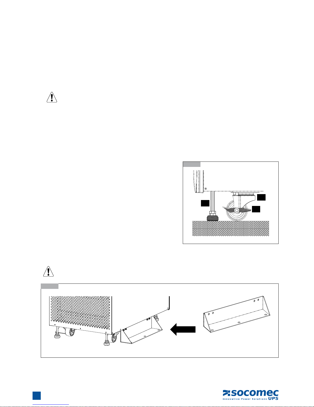
UPS Position3.5.2.
1. Position the UPS by suitable machine.
2. Ensure that the UPS is positioned at a suitable floor which can sustain
for the weight.
3. After positioning the UPS, ensure to push C (Stop) to “ON” until strictly
fastened and adjust leveler to the floor.
4. Attach the balance supporter to the UPS with bolts.
The UPS may topple over under unexpected conditions withoug balance supporter. Be sure to mount two balance
supporters on both sides of the UPS for safety reasons.
3.5.2-1
3.5.2-2
Balance
Supporter
A
B
C
A : Leveler
B : Caster
C : Stop
002 DRWMODGP-XX003 DRWMODGP-XX

11
MODULYS Green Power - Ref.: IOMMODGPXX01-GB 00
ENGLISHENGLISH
FRONT AND REAR VIEWS4.
AUX MAINS
Q2 INPUTQ2
OUTPUTQ3
Q4
BY-PASS
Q5
225A 225A
225A
225A
Mimic panel
Parallel
port
Input
Dry Contact
Output
Dry Contact
Q3
Output
Power
connections
Q5
By-passQ4Aux MainsQ1Input
Slots for optional
communication cards
004 DRWMODGP-XX
005 DRWMODGP-XX

12
MODULYS Green Power - Ref.: IOMMODGPXX01-GB 00
CONNECTIONS5.
L1
X10
L2
MAINS SUPPLY
L3 N1 L11
X40 X20
L21
AUXILIARY MAINS EXT BATTERY
L31 N11
N
240V DC 240V DC
L12
X50
L22
OUTPUT
L32 N2
5.1-1
Mains and Aux Mains connected separately5.1.
The UPS must not operate without the neutral connection to the input.
For equipment with separate Emergency Mains, it must be possible to make the neutral of the Emergency Mains
line electrically common with the neutral of the main input feed line.
L1
X10
L2
MAINS SUPPLY
L3 N1 L11
X40 X20
L21
AUXILIARY MAINS EXT BATTERY
L31 N11
N
240V DC 240V DC
L12
X50
L22
OUTPUT
L32 N2
5.2-1
Mains and Aux Mains connected in common5.2.
Cable specifications:
• stripping lenth: 20 mm
• tightening torque: 10 Nm
WARNING!
In case of a generator connection or unstable Auxiliary Mains,
only the common connection can be used.
MAINS
MAINS
LOAD
LOAD
AUX MAINS
006 DRWMODGP-XX007 DRWMODGP-XX

13
MODULYS Green Power - Ref.: IOMMODGPXX01-GB 00
ENGLISH
External battery cabinet connection5.3.
WARNING!
Before carrying out any operation, ensure that:
• the battery fuses located inside the battery cabinet are open;
• the UPS is not live and all mains or battery switches are open;
• the switches upstream of the UPS are open.
Do not open the battery breaker on the battery cabinet when the UPS is on Battery Mode.
Use double insulated cables or the cables supplied with the unit to connect the UPS to the Battery cabinet.
Cabling errors with inversion of the battery polarity may cause permanent damage to the equipment.
If using cabinets not supplied by the manufacturers of the UPS, it is the installer’s responsibility to check the
electrical compatibility and the presence of appropriate protection devices between the UPS and the battery
cabinet (fuses and switches of sufficient capacity to protect the cables from the UPS to the battery cabinet).
As soon as the UPS is switched on (before closing the battery switches) the battery parameters must be verified accordingly (voltage, capacity, number of strings, etc.) on the mimic panel menu. If the values indicated
on the battery cabinet data plate are different from those shown on the mimic panel, use the CONTROL &
CONFIG > BATTERY SETTING menu to correct the settings. Use lead acid batteries with 12 VDC nominal voltage (MR 20+20)
Cable length: 10 m max
5. CONNECTIONS
L1
X10
L2
MAINS SUPPLY
L3 N1 L11
X40 X20
L21
AUXILIARY MAINS EXT BATTERY
L31 N11
N
240V DC 240V DC
L12
X50
L22
OUTPUT
L32 N2
5.3-1
TO BATTERY CABINET
009 DRWMODGP-XX

14
MODULYS Green Power - Ref.: IOMMODGPXX01-GB 00
5. CONNECTIONS
Parallel connection5.4.
Mains and Aux Mains connected separately5.4.1.
1. Confirm if the input and bypass input breaker (Q1 and Q4) are cut off.
2. Confirm if the manual bypass circuit breaker (Q5) is cut off.
3. Confirm if the output breaker (Q3) is cut off.
4. According to UPS model you have selected, make use of a suitable cable and lug.
5. Connect all cables to the right terminal or location as indicated.
6. Connect the parallel communication cable between UPS1 and UPS2.
7. Set both dip-switches to ON position.
The sum of AUX Mains cable length and OUTPUT cable length must be the same for each system. This regulation
prevents unbalanced load shared by two UPSs under by-pass mode (i.e.: AUX Mains cable 1 + OUTPUT cable 1
= AUX Mains cable 2 + OUTPUT cable 2).
For equipment with separate AUX Mains, it must be possible to make the neutral of the Aux Mains line electrically
common with the neutral of the main input feed line.
5.4.1-1
Wiring (Parallel Redundancy, Single Input)
Output
Output 1
Parallel Cable
Output 1
LOAD
AUX COMM
AUX MAINS 1
AUX MAINS 2
MAINS 1
MAINS 2
EXTERNAL
COUPLING
CABINET
Output
Aux mains
Aux mains
Bypass
breaker
Output
breaker
Mains
Mains
UPS1
UPS2
Parallel Port
Parallel Port
010 DRWMODGP-XX

15
MODULYS Green Power - Ref.: IOMMODGPXX01-GB 00
ENGLISH
5. CONNECTIONS
Mains and Aux Mains connected in common5.4.2.
1. Confirm if the input and bypass input breaker (Q1 and Q4) are cut off.
2. Confirm if the manual bypass circuit breaker (Q5) is cut off.
3. Confirm if the output breaker (Q3) is cut off.
4. According to UPS model you have selected, make use of a suitable cable and lug.
5. Connect all cables to the right terminal or location as indicated).
6. Connect the parallel communication cable between UPS1 and UPS2.
7. Set both dip-switches to ON position.
The sum of AUX Mains cable length and OUTPUT cable length must be the same for each system. This regulation
prevents unbalanced load shared by two UPSs under by-pass mode (i.e.: AUX Mains cable 1 + OUTPUT cable 1
= AUX Mains cable 2 + OUTPUT cable 2). AUX Mains cable length is the same than Mains cable length.
For equipment with separate AUX Mains, it must be possible to make the neutral of the AUX Mains line electrically
common with the neutral of the main input feed line.
5.4.2-1
Wiring (Parallel Redundancy, Dual Input
Output
Output 1
Parallel Cable
Output 1
AUX
MAINS MAINS
LOAD
AUX COMM
EXTERNAL
COUPLING
CABINET
Output
Aux mains
Aux mains
Bypass
breaker
Output
breaker
Mains
Mains
UPS1
UPS2
Parallel Port
Parallel Port
011 DRWMODGP-XX

16
MODULYS Green Power - Ref.: IOMMODGPXX01-GB 00
WARNING!
Only trained persons familiar with the construction and operation of the equipment, as well as the electrical and
mechanical hazards involved, may install and remove system components.
WARNING!
Before removing any Power Module, ensure that the remaining Power Modules can support the load.
Follow the instructions below to replace or install the Power Module in the system.
WARNING!
Before removing any Power Module, ensure that the remaining Power Modules can support the load.
CAUTION!
Power module are heavy. Two people are required for handling.
POWER MODULE INSTALLATION6.
Installation6.1.
6.1-3
6.1-11
6.1-6
6.1-4
6.1-7
6.1-2
6.1-10
6.1-1
6.1-9
6.1-5
6.1-8
012 DRWMODGP-XX015 DRWMODGP-XX018 DRWMODGP-XX021 DRWMODGP-XX
013 DRWMODGP-XX016 DRWMODGP-XX019 DRWMODGP-XX022 DRWMODGP-XX
014 DRWMODGP-XX017 DRWMODGP-XX020 DRWMODGP-XX

17
MODULYS Green Power - Ref.: IOMMODGPXX01-GB 00
ENGLISH
Status LED Indicators for Power Module6.2.
Each power module features one LED to help inform the user about the power module status.
LED status:
“OFF”:
When the locking latch is located at “
”, the power module is inactive.
When the locking latch is located at “
” and the main power is turned on, the power module is failed.
“FLASHING”:
The power module is failed and off line.
“ON”:
The power module is active.
Note:
While releasing the locking latch of power module during normal mode, the power module is off line and discharges the DC bus until
the DC bus voltage reaches safety level. Then, the LED will be off.
6.2-1
Locking
device
Status LED
6. POWER MODULE INSTALLATION
023 DRWMODGP-XX

18
MODULYS Green Power - Ref.: IOMMODGPXX01-GB 00
MODULYS 3/3 120 kVA
LOAD PROTECTED
ESC
OFF
ON
7.1-1
Mimic panel
7.1-2
Ideograms
MIMIC PANEL7.
Mimic panel7.1.
The LCD mimic panel provides all the information relating to operating status, electrical measurements, access to controls
and configuration parameters.
A. ideograms that identify the subsets and the energy flow;
B. multicoloured luminous bar that identifies the condition of the power supply to the load;
C. alphanumeric information that uses a menu layout to provide details on any alarms that may occur and on the measurements,
controls and parameters.
D. use of the buttons:
· ON: UPS start up (inverter ON);
· OFF: UPS shutdown (inverter OFF);
· ESC: exit from the current menu/parameter/action;
· UP : scrolls the available menus/values upwards.
· DOWN : scrolls the available menus/values downwards.
· ENTER: enters the menu displayed on the screen to confirm the choice/changes made.
A
B
C
D
2
1
6 7
5
8 10 129 11 13
3 4
15
14 14
16
17
18
024 DRWMODGP-GB025 DRWMODGP-XX

19
MODULYS Green Power - Ref.: IOMMODGPXX01-GB 00
ENGLISH
7. MIMIC PANEL
Item Symbol
Description Condition
1
Load on bypass, Eco-mode or
Maintenance bypass closed.
Steady
Automatic bypass alarm. Flashing
2
Input rectifier active. Steady
Input rectifier general alarm. Flashing
3
Battery OK Steady
Battery alarm. Flashing
4
Inverter on Steady
Inverter general alarm. Flashing
5
Output voltage present. Steady
6
Input mains OK. Steady
Input mains alarm. Flashing
7
Inverter on. Steady
8 ÷13
Module present. Each module: 20 kVA Steady
Module general alarm. Flashing
14
Load present. Steady
Overload. Flashing
15
Output load indicator. Steps of 10%
16
Activation code alarm. Steady
General alarm. Flashing
17
Periodic maintenance alarm/warning. Flashing
18
LAN connection ready (cable connected). Steady
Meaning of the luminous bar.7.3.
The luminous bar (figure 7.1-1) provides an immediate indication of the condition of the power supply to the load:
General description Colour UPS conditions
Output power supply not present or
imminent shutdown
RED flashing
Imminent stop: the load will be
disconnected in 2 minutes.
Battery low when load on Battery Mode.
RED Load is not supplied.
Output power supply present but unstable or temporary
YELLOW flashing
The UPS switches off by remote
shutdown only.
UPS in stand by
YELLOW
Load on by-pass.
Load on battery Mode
Redundacy lost
Output power supply available and
regular by inverter.
GREEN flashing Battery test in progress
GREEN Load on inverter
Meaning of ideograms7.2.

20
MODULYS Green Power - Ref.: IOMMODGPXX01-GB 00
LCD display hierachy7.4.
7. MIMIC PANEL
UPS ICONS
LOAD STATUS
ALARMS
MEASURE
CONTROL AND CONF.
User password required.
User password: 1234
INPUT (MAINS AND BYPASS)
ACTIVE ALARMS
BYPASS SETTING
COMMISSIONING CLEAR STATISTICS
INVERTER OUTPUT
OUTPUT SETTING
SERIAL NUMBER CLEAR LOG
INVERTER OUTPUT
BATTERY SETTING
FW VERSION MAINTENANCE ALARM
INVERTER OUTPUT
CHARGER SETTING
STATISTICS COMMISSIONING
OUTPUT
PARALLEL SETTING
LOGGING POWER FACTOR
BATTERY
CONTROL AND TEST
ADVANCE
Admin password required.
FW UPGRADE
OTHERS
TEMPERATURE
LOCAL SETTING
SERVICE

21
MODULYS Green Power - Ref.: IOMMODGPXX01-GB 00
ENGLISH
OPERATING PROCEDURES8.
On line operations8.1.
ON LINE operation consists of double conversion operation in conjunction with mains absorption with very low distortion. This
enables the UPS to supply a voltage that is fully stabilised in frequency and amplitude, regardless of any interference in the mains
power supply.
ON LINE operation provides three operating modes according to mains and load conditions:
• “Normale” mode.
This is the most frequent operating condition: the energy is drawn from the primary mains power supply and is converted and used
by the inverter to generate the output voltage to power the loads connected. The inverter is constantly synchronised in frequency
with the auxiliary mains to enable load transfer (due to an overload or inverter shutdown) without any break in the power supply
to the load. The battery charger supplies the energy required to maintain or recharge the battery.
• “Bypass” mode.
In case of inverter failure, the load is automatically transferred onto the auxiliary mains without any interruption in the power supply.
This procedure may occur in the following situations:
- in the event of a temporary overload, the inverter continues to power the load. If the condition persists, the UPS output is
switched onto the auxiliary mains via the automatic bypass. Normal operation, which is from inverter, returns automatically a
few seconds after the overload disappears.
- when the voltage generated by the inverter goes is out of tolerances due to a major overload or a fault on the inverter.
- when the internal temperature exceeds the maximum value allowed.
• “Battery” mode.
In the event of a mains failure (micro interruptions or extended black-outs), the UPS continues to power the load using the energy
stored in the battery. The mimic panel keeps the user constantly informed on the battery status and on the remaining capacity
available.
Operation in high effi ciency "Eco-mode"8.2.
Operation in ECO-MODE can increase overall efficiency by up to 98% and, at the same time, energy savings can be achieved. If
the mains supply fails, the UPS will automatically switch onto the inverter and continue to supply power to the load through the
batteries. Unlike ON LINE operation, operation in ECO-MODE does not provide perfect stability in frequency and voltage; use of
this mode should therefore be carefully evaluated according to the level of protection required by the application. ECO-MODE is
not available for parallel connection.
Converter mode8.3.
Converter mode enables the UPS to operate as a frequency converter. The available frequency setting for the output is either fixed
50 Hz or fixed 60 Hz. The AUX MAINS is NOT considered as available in this mode, because AUX MAINS frequency could be
different from the output frequency. Use
or to select the desired frequency, then press to confirm (this setting is only for
battery start condition or when frequency mode converter is enabled).
WARNING!
Converter mode has to be set only in case of separated MAINS and AUX MAINS and with AUX MAINS disconnected!
Do not set in case of common mains as it could damage the load.
Operation with manual maintenance bypass8.4.
If the manual bypass is activated (with the appropriate procedure), the load is powered directly from the auxiliary mains, while the
UPS is in fact excluded from the power supply and can be switched off.
This operating mode is useful when maintenance needs to be carried out on the UPS since service personnel can work on the
installation without having to cut off the power supply to the load.

22
MODULYS Green Power - Ref.: IOMMODGPXX01-GB 00
8. OPERATING PROCEDURES
Commissioning8.5.
During activation of the equipment a warranty activation code, made up of four characters, is requested to complete the start-up
procedure. The activation code is provided directly by the reference Support Centre upon communication of the serial number of
the equipment which is displayed in the message at first start procedure.
SEE INSTALLATION MANUAL
FOR PROCEDURE
SN: 0000000000
When contact is made with the Support Centre for the activation code, detailed information can be obtained on the UPS functions
available and on the periodic preventive maintenance programmes. Once the code is obtained, enter it by pressing ENTER to activate the entry. Select the first character with the UP and DOWN keys and confirm with ENTER to accept the character. Then
move on to the next character. Pressing the ENTER key after selecting the fourth character activates code.
SEE INSTALLATION MANUAL
FOR PROCEDURE
CODE = A A A A
An error message is displayed if the code is incorrect. Check that the code displayed corresponds to the one provided by the
Support Centre and repeat the procedure.
Single Unit (up to 120 kVA)8.6.
Startup Procedures8.6.1.
Before starting up the UPS system, be sure to check the following items first.
• Ensure all circuit breakers are cut off and switched to OFF, as well as the breaker or fuse of the external battery cabinet.
• Confirm if the locking latch is located at position in the power module.
• Confirm if the input power source matches the rated voltage, frequency, phase and battery of the UPS that you have installed.
If the conditions mentioned above are satisfied, follow the steps below to start up.
1. If there is an external battery cabinet, switch the circuit breaker of battery cabinet to ON and confirm if manual bypass protection
circuit breaker Q5 (BY-PASS) is cut off and switched to OFF.
2. Switch on Q1 (INPUT), Q4 (AUX MAINS) and Q3 (OUTPUT). The LCD monitor will start displaying. After initialization, the LCD
screen will show ”LOAD NOT SUPPLIED”.
3. Press the “ON” button for 3 seconds until you hear a “beep” and then release the button.
4. At this time, the LCD screen will show "SELF DIAGNOSIS" and after 30 seconds the load is powered by the UPS.
Battery Startup Procedures8.6.2.
1. Switch the circuit breaker of external battery cabinet to ON and confirm if Q5 (BY-PASS) is cut off and switched to OFF.
2. Switch on Q3 (OUTPUT).
3. Press the “ON” button for 3 seconds until you hear a “beep” and then release the button. The LCD screen will show "SELF
DIAGNOSIS".
4. The UPS will start up by DC-bus soft start. The inverter will be activated by adopting the default frequency value.
5. When the inverter startup is completed, the UPS will transfer to Inverter mode and the luminous bar turns to yellow colour.
6. The load is powered by the ups in battery mode.

23
MODULYS Green Power - Ref.: IOMMODGPXX01-GB 00
ENGLISHENGLISH
8. OPERATING PROCEDURES
Shutdown Procedures8.6.3.
This operating procedure can cut off all the power supply. Be sure to confirm if the loads are turned off first! Refer to following
steps.
1. Press the “OFF” button for 3 seconds until you hear a “beep” and then release button. The LCD screen will show “SHUTDOWN
UPS?”, then selected “YES” and press to confirm.
2. The UPS will shut down the inverter and cut off the output power. The luminous bar turns to yellow blinking.
3. Switch off Q1 (INPUT).
4. Switch off Q4 (AUX MAINS).
5. Confirm if the UPS is turned off and all the circuits are off.
6. If there is an external battery cabinet, switch off the circuit breaker of battery cabinet.
7. Switch off Q3 (OUTPUT).
Switching onto manual bypass8.6.4.
Switching onto the manual bypass creates a direct connection between the ups input and output, completely excluding the equipment control part. This operation is performed in the event of ordinary maintenance of the equipmnet, so as not to remove the
power supply from the load, or in the event of a serious failure while waiting for the equipment to be repaired.
1. From the mimic panel set "ECO MODE" to "ON" (CONTROL & CONFIG>OUTPUT>ECO>ON). Use user password "1234" to
enter the "ECO MODE".
2. After "ECO MODE" wait about 30 seconds and close Q5 (BY-PASS)
3. Switch off Q1 (INPUT).
4. Switch off Q4 (AUX MAINS).
5. Switch off Q3 (OUTPUT).
6. If there is an external battery cabinet, switch off the circuit breaker of battery cabinet.
1. Only for maintenance purpose, you can manually turn on the bypass switch “Q5”. If you switch on Q5 (BY-PASS)
under normal condition, the inverter will shut down and the output will be supplied by manual bypass
source.
2. Manual bypass mode ensures that the UPS supplies the loads from manual bypass source. The service personnel can perform maintenance process under this mode without interrupting the loads. At this moment, the UPS
is still supplied by input power source. If the service personnel want to replace any circuit board or component,
please power off the UPS (please refer to 8.1.3) first.
Return to normal mode (from manual bypass)8.6.5.
1. Switch on Q1 (INPUT).
2. Switch on Q4 (AUX MAINS).
3. Switch on Q3 (OUTPUT).
4. If there is an external battery cabinet, switch on the circuit breaker of battery cabinet.
5. The LCD screen will show “LOAD UNPROTECTED". Verify the steady condition of the black bar "LOAD ON BYPASS" on the
LCD screen (please refer to 7.2).
6. Set "ECO MODE" to "OFF" on the mimic panel (CONTROL & CONFIG > OUTPUT > ECO > OFF). Use user password "1234"
to enter the "ECO MODE".
7. Switch off Q5 (BY-PASS).
8. Press the “ON” button for 3 seconds until you hear a “beep” and then release the button. The LCD screen will show "SELF
DIAGNOSIS".
9. The load is powered by the ups in normal mode (LOAD PROTECTED).

24
MODULYS Green Power - Ref.: IOMMODGPXX01-GB 00
Two units in parallel (up to 240 kVA)8.7.
Startup Procedures8.7.1.
Before starting up the UPS system, be sure to check the following items first.
• All circuit breakers are cut off and switched to OFF, as well as the breaker or fuse of the external battery cabinet.
• Confirm if the locking latch is located at in the power module.
• Confirm if the input power source matches the rated voltage, frequency, phase and battery of the UPS that you have installed.
For UPSs in parallel:
- Carry out the procedures on all the UPSs before going on to the next operation. Each procedure should be
carried out on all the UPS within 30 seconds.
- For parallel redundancy installation, you must set the ID code of each UPS as “01” and “02” by configuring the
control panel. Please refer to chapter 7 (Parallel setting - LCD menu).
• Start up procedure: please refer to 8.6.1. Repeat the procedure for both UPS.
Shutdown Procedure8.7.2.
For the shutdown procedure please refer to 8.6.3. Repeat the procedure for both UPS.
Switching onto manual bypass8.7.3.
Switching onto the manual bypass creates a direct connection between UPS input and output, completely excluding the equipment
control part. This operation is performed in the event of ordinary maintenance of the equipmnet, so as not to remove the power
supply from the load, or in the event of a serious failure while waiting for the equipment to be repaired.
1. Switch on the coupling cabinet by-pass breaker.
2. Switch off Q1 (INPUT), switch off Q4 (AUX MAINS), switch off Q3 (OUTPUT) of both UPSs.
3. If there is an external battery cabinet, switch off the circuit breaker of battery cabinet of both UPSs
4. The system is in manual bypass.
Return to normal mode (from manual bypass)8.7.4.
1. Switch on Q1 (INPUT), switch on Q4 (AUX MAINS), switch on Q3 (OUTPUT) of both UPSs
2. If there is an external battery cabinet, switch on the circuit breaker of battery cabinet of both UPSs
3. Verify the steady condition of the black bar "LOAD ON BYPASS" on the LCD screen of both UPSs (please refer to 7.2).
4. Switch off the coupling cabinet by-pass breaker.
5. Press the “ON” button for 3 seconds until you hear a “beep” and then release the button. The LCD screen will show "SELF
DIAGNOSIS" and after 30 seconds the load is powered by the ups. Repeat the procedure for each UPS.
8. OPERATING PROCEDURES

25
MODULYS Green Power - Ref.: IOMMODGPXX01-GB 00
ENGLISHENGLISH
POWER MODULE REPLACEMENT9.
Status LED Indicators for Power Module9.1.
Each power module features one LED to help inform the user about the power module status.
LED status:
• OFF:
- When the locking latch is located at
, the power module is inactive.
- When the locking latch is located at
and the main power is turned on, the power module is failed.
• FLASHING: the power module is failed and off line.
• ON: the power module is active.
Note:
While releasing the locking latch of power module during normal mode, the power module is off line and discharges the DC bus until
the DC bus voltage reaches safety level. Then, the LED will be off.
Power Module Replacement9.2.
WARNING!
Only trained persons familiar with the construction and operation of the equipment, as well as the electrical and
mechanical hazards involved, may install and remove system components.
WARNING!
Before removing any Power Module, ensure that the remaining Power Modules can support the load.
Follow the instructions below to replace the Power Module in the system.
CAUTION!
Power module are heavy. Two people are required for handling.
9.1-1
028 DRWMODGP-XX

26
MODULYS Green Power - Ref.: IOMMODGPXX01-GB 00
9. POWER MODULE REPLACEMENT
9.2-3
9.2-11
9.2-11
9.2-11
9.2-6
9.2-4
9.2-7
9.2-2
9.2-10
9.2-10
9.2-1
9.2-9
9.2-5
9.2-8
012 DRWMODGP-XX029 DRWMODGP-XX032 DRWMODGP-XX019 DRWMODGP-XX021 DRWMODGP-XX
013 DRWMODGP-XX030 DRWMODGP-XX016 DRWMODGP-XX018 DRWMODGP-XX022 DRWMODGP-XX
014 DRWMODGP-XX031 DRWMODGP-XX017 DRWMODGP-XX020 DRWMODGP-XX

27
MODULYS Green Power - Ref.: IOMMODGPXX01-GB 00
ENGLISH
PARALLEL PARALLEL
OUTPUT DRY CONTACT
P1 P3 P4 P5 P6P2 P7
123456789101112
COMMUNICATION INTERFACE10.
Input Dry Contact10.1.
P1 - REPO (Remote Emergency Power OFF)
It provides a convenient method for users remotely power off the UPS if an emergency event occurs. Simply connect the cable from
remote site to this terminal. The user may install a switch to easily power off the UPS. This REPO is a normal open contact.
P1
External contact
1 2
P2 - Dry Contact Input (Two sets)
The UPS provides two sets of dry contact input to receive external signals and then the UPS can take corresponding response.
These contacts belong to “normal open” type:
• P2 (1,2) - AC GENERATOR FUNCTION: limit the charger current (3 A) when using generator source
• P2 (3,4) - REMOTE SHUTDOWN FUNCTION: available in Normal Mode and Battery Mode. The UPS switches off after 1 minute.
P3-P4-P5-P6 - External Battery Cabinet Temperature
Available as standard, the “sensor kit” allows to detect the temperature of external battery cabinet.
P7 - Reserved
Slots for optional communication cards
Parallel port Output Dry Contact Input Dry Contact
10-1
Communication interfaces
033 DRWMODGP-XX
041 DRWMODGP-XX
042 DRWMODGP-XX
28
MODULYS Green Power - Ref.: IOMMODGPXX01-GB 00
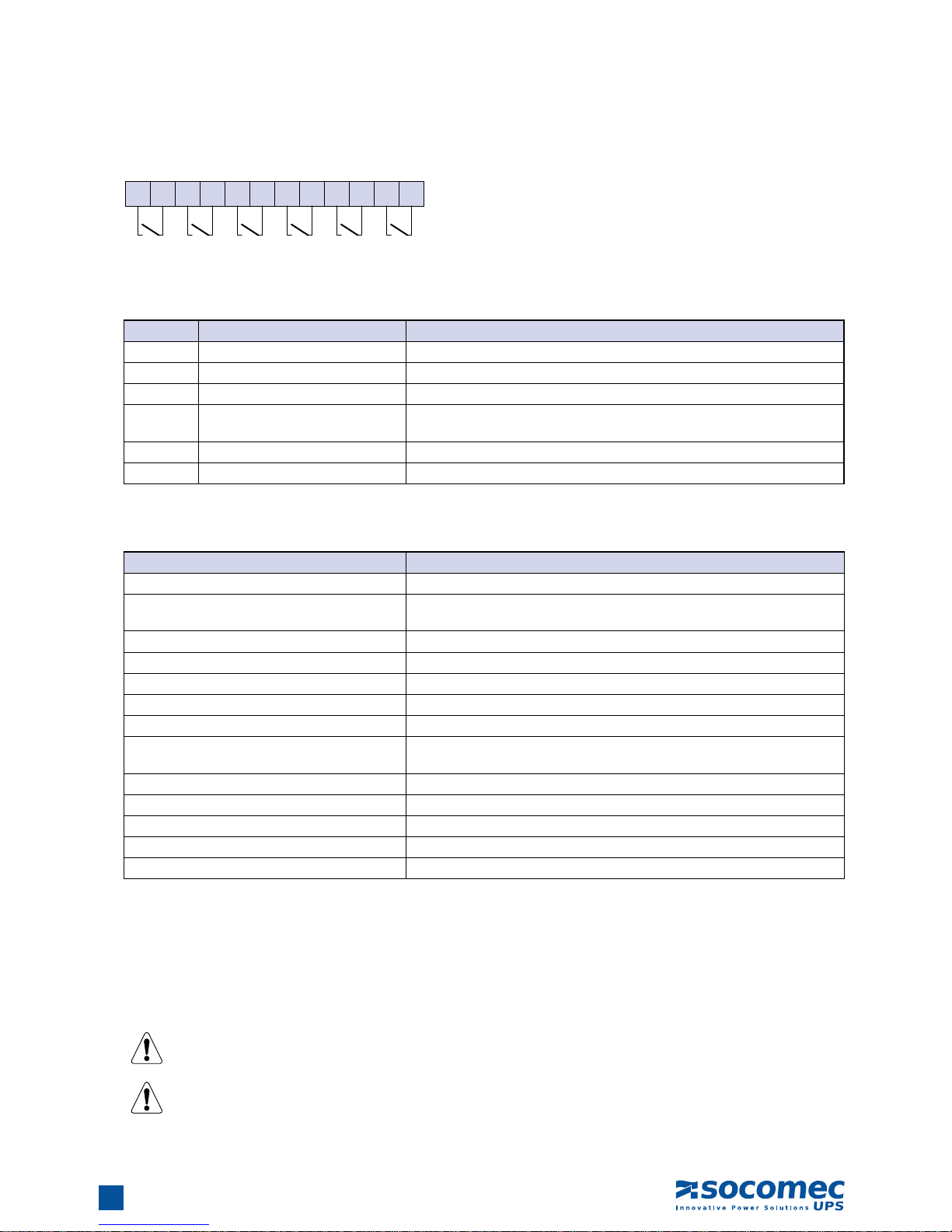
Output Dry Contact10.2.
1 2 3 4 5 6 7 8 9 10 11 12
The UPS provides 6 dry contact outputs that can be set to normally open or normally close via SNMP web card. The default contact
position is NO. The default message is shown in the tables below. NO or NC contacts admitted nominal current: 2 A 250 VAC
Contact Message Description
1-2 Input backfeed Input backfeed is activated
3-4 Bypass backfeed Bypass backfeed is activated
5-6 Load on Battery The UPS is on Battery mode
7-8 Battery Low
The UPS is on Battery mode and the battery voltage is closed to the lower
limit (battery voltage < 220 V)
9-10 Load on auto by-pass The UPS is in bypass mode
11-12 General Alarm At least one active alarm is present
Contacts 5-6, 7-8, 9-10, 11-12 can also be settable via SNMP web card for monitoring the following UPS status.
Message Description
Internal communication failure The communication of module is abnormal.
External parallel communication failure
During installation of the parallel redundancy, the parallel communication is
abnormal.
Output overload warning/shutdown The loading is over rated output of the UPS.
Power module fault shutdown The module fails and the UPS is shut down.
Power module warning The module has errors, but the UPS can still function normally.
EPO activated Urgently power off the UPS.
Load on manual bypass The UPS transfers to manual bypass mode.
Battery cabinet over temperature warning/shut-
down
The temperature is too high.
Output voltage abnormal The output voltage is too high or too low.
Battery need replace Overdue for battery replacement (Compared with system setup.)
Bypass over temperature warning/shutdown Bypass “static transfer switch” is over temperature.
Battery ground fault Grounding error
Bypass static switch fault The bypass “static transfer switch” is abnormal.
Parallel port10.3.
For redundancy or for increasing the power, two UPSs can be installed via a parallel communication cable.
Use the parallel communication cable provided in the accessory pack.
Linking the UPS with other cables will result in accidents.
Both dip-switches has to be set to ON.
10. COMMUNICATION INTERFACE
043 DRWMODGP-XX

29
MODULYS Green Power - Ref.: IOMMODGPXX01-GB 00
ENGLISH
10. COMMUNICATION INTERFACE
SNMP card10.4.
On board SNMP adapter allows the UPS to be monitored over networks as a peripheral. The adapter sends out traps on UPS alarms
that can be monitored using a Network Management Software or via web browser. It can be used in conjunction with JNC client to
perform an orderly shutdown of critical and virtual servers within the enterprise network.
Specifications:
• SNMP agent and web server implemented in UPS supporting the following protocols: ARP, IP, ICMP, SNMPv1, SNMPv3 USM,
UDP, TCP, HTTP, FTP, TFTP, SMTP, BOOTP, SNTP, DN and Telnet.
• Security login by MD5 .
• User level management.
• Firmware upgrade for new features through TFTP.
• Batch configuration through FTP.
• Save event logs and history values of UPS in EEPROM.
• Scheduled UPS shutdown, restart and test.
• Wake-On-LAN packet to wake up PC.
• Send the e-mail and SNMP trap to notify users.
• Provides JNC software to protect public operating systems.
• Provides the InsightPower EzSetting software to easily configure for the first time and upgrade firmware.
Dip Switch Mode
SW1
SW2 Mode
ON ON Configuration
ON OFF For Environmental Sensor
OFF ON Pass Through
OFF OFF Normal
Programmable Relay I/O Card (option)10.5.
Specifications:
• The status information on UPS is presented as 6 contact closures and programmable output contacts.
• UPS event monitoring in various application practices.
• Configurable UPS shutdown delay time.
• Configurable input signal during UPS shutdown or battery test.
• Provides graceful unattended shutdown to protect up to 6 computers.
Modbus protocol (option)10.6.
MODBUS protocol over TCP/IP allows to connect the UPS to a network (Ethernet connection).
EMD - Environmental Monitoring Device (option)10.7.
It is a digital environmental monitoring system for the surveillance of networking cabinet’s temperature, humidity and
secures alarms in the room environment.

30
MODULYS Green Power - Ref.: IOMMODGPXX01-GB 00
TROUBLESHOOTING11.
UPS
Alarm message Condition
MAINS INPUT VOLT OR FREQ NOK
Main input voltage abnormal (load <70%: 120÷276 V, load >70%: 173-276 V ).
Main input frequency abnormal (45-65 Hz )
MAINS INPUT PHASE SEQ NOK Main input phase sequence abnormal
BYPASS INPUT VOLT OR FREQ NOK
Bypass voltage over rating (220/230/240 V) ±15%
Bypass Freq. over rating (50/60 Hz ) ± 5 Hz
BYPASS INPUT PHASE SEQ NOK Bypass phase sequence abnormal
BAT TEST FAIL Battery capacity too low
BAT OVER CHARGE Battery voltage > 296 V
BYPASS STS OVER HEAT Bypass STS temperature over 80 °C
BYPASS STS OVER CURRENT Bypass loading over 175%
BYPASS STS ALARM Bypass STS open/short
PWR UNIT #n COMMUNICATION NOK 1. CAN BUS - 2. SCI - 3. Power Module internal communication
BAT BAD Battery voltage < 190 V
SYS FAN FAIL Bypass FanA/B/C fail
UPS OUTPUT FAULT SHUTDOWN UPS output voltage over rating ( 220/230/240 V ) ±10 V
EXT PARALLEL COMMUNICATION NOK Parallel CAN BUS loss
PARALLEL FAIL PID conflict or system KVA rating not the same
REDUNDANCY LOSS UPS lost redundancy
ON MANUAL BYPASS Manual bypass on
BAT LOW WARNING Battery voltage: 200÷220 V
LOW BAT CUT OFF Battery voltage < 200 V
BAT REPLACE REQUIRED Battery package out of date
INV OVERLOAD WARNING Loading over 105%
INV OVERLOAD SHUTDOWN 105%÷125% 10 min - 125%÷150% 1min - 150% 1sec
INV OVER CURRENT Output current over 80 A/phase
EMERGENCY OFF E.P.O./ Remote E.P.O. ON
OUTPUT BREAKER OFF Output breaker not turn on
BYP OVERLOAD WARNING 104% overload when UPS is on bypass
BAT CABINET OVER HEAT Battery cabinet over 35 °C
EXT BAT BREAKER OFF If supported by the external battery and battery breaker is OFF
Power Module (#n is indicated the ID of power Module. (Ex.: #1 is Power module 1))
Alarm message Condition
PWR UNIT #n PFC FUSE OPEN SHUTDOWN Power module #n main input fuse broken
PWR UNIT #n INV FUSE OPEN SHUTDOWN Power module #n output fuse broken
PWR UNIT #n GENERAL FAULT PFC/INV control board fail
PWR UNIT #n CHARGER FAIL Power module #n charger board fail
PWR UNIT #n FAN FAIL Power module #n fan(s) fail
PWR UNIT #n PFC OVER HEAT WARNING Power module #n PFC temperature over 60 °C
PWR UNIT #n PFC OVER HEAT SHUTDOWN Power module #n PFC temperature over 65 °C
PWR UNIT #n INV OVER HEAT WARNING Power module #n INV temperature over 60 °C
PWR UNIT #n INV OVER HEAT SHUTDOWN Power module #n INV temperature over 65 °C
PWR UNIT #n INV OUTPUT NOK SHUTDOWN Power module #n INV voltage over rating
PWR UNIT #n INV SHORT CIRCUIT SHUTDOWN (220/230/240 V) ± 1%
PWR UNIT #n INV STS FAIL SHUTDOWN UPS output short circuit
PWR UNIT #n DC BUS NOK SHUTDOWN Power module #n STS open/short
The alarm messages displayed enable an immediate diagnosis. Alarms are divided into two categories:
• Alarms related to the UPS external circuits: input mains, output mains, temperature and environment.
• Alarms related to the UPS internal circuits: in this case, the corrective actions will be carried out by the After Sales Department.

31
MODULYS Green Power - Ref.: IOMMODGPXX01-GB 00
ENGLISH
11. TROUBLESHOOTING
Preventative maintenance11.1.
We would like to inform you that specialised periodic maintenance (with yearly frequency) is recommended for the
Modulys green power, in order to offer optimum operating efficiency and avoid downtime of the equipment.
It is strongly recommended to give due consideration to any requests for preventive maintenance automatically
displayed.
All operations on the equipment must be only carried out by SOCOMEC UPS personnel or by authorised support
personnel.
Maintenance consists of accurate functional checks on electronic and mechanical parts with replacement of parts
subject to wear if necessary (typically batteries, fans and capacitors).
Batteries.11.2.
The state of the battery is fundamental to UPS operation.
Thanks to the Expert Battery System, the information relating to the state and the conditions of use of the battery are
processed in real time and the recharging and discharging procedures are selected automatically in order to optimise
battery life expectancy and offer maximum performance.
Furthermore, during the operating life of the battery, Modulys green power stores statistics on the conditions of use
of the battery for analysis.
Since the expected life of the batteries is very much dependent on operating conditions (number of charging and
discharging cycles, load rate, temperature), a periodic check by authorised personnel is recommended.
When replacing the batteries, use the same type and configuration by placing them in the appropriate containers
so as to avoid the risk of acid leakage. The replaced batteries must be disposed of at authorised recycling and
disposal centres. Do not open the plastic cover of the batteries as they contain harmful substances.
Fans.11.3.
The life of the fans used to cool the power parts is dependent on the using and environmental conditions (temperature,
dust). Preventive replacement by an authorised technician is recommended.
When needed, fans should be replaced as per specifications by SOCOMEC UPS.
Capacitors.11.4.
The equipment houses electrolytic capacitors (used in the rectifier and inverter section) and filtering capacitors (used
in the output section), whose life is dependent on using and environmental conditions.
In any case the effective state of the components is verified during preventive maintenance.

32
MODULYS Green Power - Ref.: IOMMODGPXX01-GB 00
TECHNICAL SPECIFICATION12.
Number of modules 123456789101112
Power kVA 20 40 60 80 100 120 140 160 180 200 220 240
Redundant configuration N+1
Electrical specification - Input
Nominal voltage V 400 (3ph + N) -25% +20% (up to -50% at 70% Pn)
Input frequency Hz 50/60 ±10%
Input power factor / THDI
(1)
0.99 / < 3%
Electrical specification - Output
Output voltage V 400 (3ph + N) ±1% (380/415 configurable)
Output frequency Hz 50/60
Automatic bypass
Nominal output voltage ±15% (configurable from 8% to 15%)
Nominal output frequence ±1 Hz (configurable from 0,5 to 5 Hz)
Overload
(2)
125% for 10', 150% for 60"
Crest factor 3:1
Voltage distortion <1%
Module
Power kVA 20
Power
(3)
kW 18
Battery charging current A 1.2 - 5
Efficiency (on-line mode) % up to 96
Efficiency (eco mode) % up to 98
Weight kg 30
Environment
Operating temperture °C 0 to +40 (15 to 25 for best battery life)
Storage temperature °C -5 to +45 (15 to 25 for best battery life)
Relative humidity % 0 to 95 without condensation
Altitude (max) m 1000 without de-rating (3000 max)
Acoustic noise dB 60 ÷ 66
Required cooling capacity m
3
/h 440 ÷ 5980
Dissipiated power (max) W 1000 ÷ 12000
Dissipiated power (max) BTU/h 3400 ÷ 41250
Dimensions and Weight - single cabinet
Dimensions (W x D x H) mm 520 x 975 x 1695 520 x 975 x 1695
Weight (empty cabinet) kg 200 200
Standards
Safety EN 62040-1 (NEMKO certified), EN 60950-1
Type and performance EN 62040-3 [VFI-SS-111]
EMC EN 62040-2
Product certification CE
Degree of protection IP20
(1)
For source THDV < 2% and nominal load.
(2)
From inverter.
(3)
@ 25 °C, set by After Sales Sevice.


VALID FOR FRANCE VALID FOR ITALY
ISO 9001
FM 28237
ISO14001
EMS 553476
Non contractual document. © 2010, Socomec SA. All rights reserved.
HEAD OFFICE
SOCOMEC GROUP
S.A. SOCOMEC capital 11 303 400 E - R.C.S. Strasbourg B 548 500 149
B.P. 60010 - 1, rue de Westhouse - F-67235 Benfeld Cedex
SOCOMEC UPS Strasbourg
11, route de Strasbourg - B.P. 10050 - F-67235 Huttenheim Cedex- FRANCE
Tel. +33 (0)3 88 57 45 45 - Fax +33 (0)3 88 74 07 90
admin.ups.fr@socomec.com
SOCOMEC UPS Isola Vicentina
Via Sila, 1/3 - I - 36033 Isola Vicentina (VI) - ITALY
Tel. +39 0444 598611 - Fax +39 0444 598622
hr.ups.it@socomec.com
SALES, MARKETING AND SERVICE MANAGEMENT
SOCOMEC UPS Paris
95, rue Pierre Grange
F-94132 Fontenay-sous-Bois Cedex - FRANCE
Tel. +33 (0)1 45 14 63 90 - Fax +33 (0)1 48 77 31 12
dcm.ups.fr@socomec.com
Socomec UPS
worldwide
IN WESTERN EUROPE
BELGIUM
Schaatsstraat, 30 rue du Patinage
B - 1190 Bruxelles
Tel. +32 (0)2 340 02 34
info.ups.be@socomec.com
FRANCE
95, rue Pierre Grange
F - 94132 Fontenay-sous-Bois Cedex
Tel. +33 (0)1 45 14 63 90
info.ups.fr@socomec.com
GERMANY
Heppenheimerstraße 57
D - 68309 Mannheim
Tel. +49 (0) 621 71 68 40
info.ups.de@socomec.com
ITALY
Via Leone Tolstoi, 73 - Zivido
20098 San Giuliano Milanese (MI)
Tel. +39 02 98 242 942
info.ups.it@socomec.com
PORTUGAL
Núcleo Empresarial de Mafra II
Av. Dr. Francisco Sá Carneiro, Fracção N
2640-486 Mafra
Tel. +351 261 812 599
info.ups.pt@socomec.com
SPAIN -
IBERIAN PENINSULA
C/Nord, 22 Pol. Ind. Buvisa
E - 08329 Teià (Barcelona)
Tel. +34 935 407 575
info.ups.sib@socomec.com
THE NETHERLANDS
Bergveste 2F
NL - 3992DE Houten
Tel. +31 (0)30 63 71 504
info.ups.nl@socomec.com
THE UNITED KINGDOM
Units 7-9 Lakeside Business Park
Broadway Lane - South Cerney
Cirencester - GL7 5XL
Tel. +44 (0)1285 863300
info.ups.uk@socomec.com
OTHER COUNTRIES
Tel. +34 935 407 575
info.ups.europe@socomec.com
IN EASTERN EUROPE,
MIDDLE EAST, AFRICA
POLAND
ul. Mickiewicza 63
01-625 Warszawa
Tel. +48 22 825 73 60
info.ups.pl@socomec.com
ROMANIA
Heliade Intre Vii Street no.8, 2 District
023383 Bucharest
Tel. +40 21 319 36 88 ( 89, 81, 82)
info.ups.ro@socomec.com
RUSSIA
4th Street 8 Marta, 6A, 405
125167 - Moscow
Tel. +7 495 775 19 85
info.ups.ru@socomec.com
SLOVENIA
Savlje 89
SI - 1000 Ljubljana
Tel. +386 1 5807 860
info.ups.si@socomec.com
OTHER COUNTRIES
Tel. +39 0444 598 611
info.ups.emea@socomec.com
IN ASIA PACIFIC
AUSTRALIA
Level 9, Avaya House
123 Epping Road
North Ryde, NSW 2113
Tel. +61 2 8985 7365
info.ups.au@socomec.com
CHINA
Universal Business Park
B33, 3rd Fl, 10 Jiuxianqiao Rd.,
Chaoyang, Beijing 100016 P.R., China
Tel. +86 10 59756108
info.ups.cn@socomec.com
INDIA
B1, IInd Floor, Thiru-Vi-Ka-Industrial Estate
Guindy
Chennai – 600 032
Tel. +91 44 3921 5400
info.ups.in@socomec.com
MALAYSIA
31 Jalan SS 25/41- Mayang Industrial Park
47301 Petaling Jaya.- Selangor, Malaysia
Tel. +603 7804 1153
info.ups.my@socomec.com
SINGAPORE
31 Ubi Road 1, Aztech Building
# 01-00 (Annex) - SG - Singapore 408694
Tel. +65 6745 7555
info.ups.sg@socomec.com
THAILAND
No.9 Soi Vibhavadirangsit 42
Vibhavadirangsit Rd, Ladyao
Chatujak Bangkok 10900
Tel. +66 2 941-1644-7
info.ups.th@socomec.com
VIETNAM
539/23 Luy Ban Bich St.,
Phu Thanh Ward, Tan Phu Dist
Ho Chi Minh City
Tel. +84-839734.990
info.ups.vn@socomec.com
ASIA PACIFIC HEAD OFFICE
Tel. +65 6507 9770
info.ups.apac@socomec.com
www.socomec.com
VALID FOR FRANCE VALID FOR ITALY
ISO 9001
FM 28237
ISO14001
EMS 553476
IN AMERICA
LATIN AMERICAN COUNTRIES
Tel. +34 935 407 575
info.ups.sib@socomec.com
*IOMMODGPXX01-GB 00*
IOMMODGPXX01-GB 00 12.2010
 Loading...