

Page 1

Operating manual for
DELPHYS MP and DELPHYS MP elite
Uninterruptible Power Systems
with a mimic control panel
UPS/NTA GB/DELMP_EXPC1C3C6.B
03/04/2007
Page 2

Certificate of Warranty
The warranty conditions are stipulated in the sales contract, if not the following points shall
apply.
The manufacturer exclusively guarantees his own products against any defect in
construction or operation arising from faulty design, materials or workmanship according to
the conditions set down below.
The manufacturer, at his discretion, is entitled to adapt his product in order to comply with
the warranty or replace the faulty parts. The manufacturer’s warranty does not apply in the
following cases:
- Defects arising either from designs or parts imposed or supplied by the Purchaser.
- Failure due to fortuitous circumstances or force majeure.
- Replacements or repairs resulting from normal wear of units and machinery,
- Damage or injuries caused by negligence, lack of inspection or maintenance, or improper
use of the products.
The period of validity of the warranty may never exceed 12 months after delivery.
Replacements, repairs or modifications of parts during the warranty period cannot extend
the duration of the warranty.
For these stipulations to be valid, the Purchaser must, within a maximum of 8 days beyond
which the warranty lapses, expressly inform the Manufacturer of the faulty design, or the
material or manufacturing defect, stating in detail the grounds for his complaint.
Defective parts replaced free of charge by the Manufacturer are to be put at his disposal, so
that he may become the sole owner.
The warranty legally ceases if the Purchaser has, of his own initiative, undertaken
modifications or repairs on the Manufacturer’s products without the written consent of the
latter.
The Manufacturer’s liability is limited to the obligations as defined herein (repair or
replacement), all other items of damage being formally excluded.
The Purchaser is liable for taxes or duties of any kind in compliance with either the
European regulations, or those of the country of import or transit.
UPS/NTA GB/DELMP_EXPC1C3C6_B page 1/48
Page 3

FOREWORD
We thank you for the trust you have in our Uninterruptible Power Systems.
This equipment is fitted with up to date technology with power semiconductors (IGBT) and a digital
micro-controller.
Our equipment complies with standard IEC EN 62040-2 and 62040-1-2.
CAUTION: “This is a product for restricted sales distribution to informed partners. Installation
restrictions or additional measures may be needed to prevent disturbances”.
SAFETY REQUIREMENTS
Using conditions:
Do read carefully these operation instructions before using the UPS and comply with the safety notes
mentioned.
Whatever the repairs, they must be made only by authorised staff, who have been suitably trained. It
is recommended that the ambient temperature and humidity of the UPS environment are maintained
below the values specified by the manufacturer.
This equipment meets the requirements of the European directives applied to this product. As a
consequence it is labelled as follows:
REGULATIONS CONCERNED WITH ENVIRONMENTAL ISSUES
Recycling of electrical products and equipment
Provision is made in European countries to break up and recycle materials making up the system.
The various components must be disposed of in accordance with the legal provisions in force in the
country where the system is installed.
Battery wastes
Used batteries are considered as toxic wastes. It is therefore essential to entrust them solely and
exclusively to firms specialised in their recycling. They can not be treated with other industrial or
household wastes, as set out in local regulations in force.
UPS/NTA GB/DELMP_EXPC1C3C6_B 2
Page 4

CONTENTS
CHAPTER 1: General.........................................................................................................................................5
1.1 SCOPE.....................................................................................................................................................6
1.2 PURPOSE AND UPS COMPOSITION....................................................................................................6
1.3 SAFETY ...................................................................................................................................................7
1.4 LAYOUT OF DELPHYS MP AND DELPHYS MP ELITE SYSTEMS......................................................8
1.5 POWER SUPPLY INPUTS......................................................................................................................8
CHAPTER 2: Single units with bypass ............................................................................................................9
2.1 STANDARD BASIC SCHEMES.............................................................................................................10
2.2 LAYOUT OF SWITCHES.......................................................................................................................10
2.3 MIMIC CONTROL PANEL.....................................................................................................................11
2.3.1 Contrast setting.......................................................................................................................11
2.3.2 Luminous status bar ...............................................................................................................11
2.4 MEANING OF THE PICTOGRAMS.......................................................................................................12
2.4.1 Mimic panel description..........................................................................................................12
2.5 MENU STRUCTURE .............................................................................................................................13
2.6 OPERATING A SINGLE UPS................................................................................................................14
2.6.1 Starting up the UPS................................................................................................................14
2.6.2 Load transfer from inverter to mains ......................................................................................14
2.6.3 Load transfer from mains to inverter ......................................................................................15
2.6.4 UPS shutdown with transfer to the maintenance bypass.......................................................15
2.7 OPERATING MODE..............................................................................................................................15
CHAPTER 3: Modular systems.......................................................................................................................16
3.1 BASIC SCHEMES..................................................................................................................................17
3.1.1 Modular systems with two redundant UPS units....................................................................17
3.1.2 Modular systems with two non redundant UPS units.............................................................17
3.1.3 Modular systems with three UPS units or more.....................................................................18
3.2 LAYOUT OF SWITCHES.......................................................................................................................18
3.3 CONTROL PANEL.................................................................................................................................19
3.3.1 Contrast setting.......................................................................................................................19
3.3.2 Description of the luminous status bar...................................................................................19
3.4 MEANING OF THE PICTOGRAMS.......................................................................................................20
3.4.1 Mimic panel description..........................................................................................................20
3.5 STRUCTURE OF THE SYSTEM RELATED MENU .............................................................................21
3.6 STRUCTURE OF THE UNIT RELATED MENUS (UNIT) .....................................................................22
3.7 OPERATING THE MODULAR SYSTEM...............................................................................................23
3.7.1 Starting up the modular system..............................................................................................23
3.7.2 Load transfer from inverter to mains ......................................................................................24
3.7.3 Load transfer from mains to inverter ......................................................................................24
3.7.4 Switching to maintenance bypass - shutdown of the system.................................................25
3.7.5 System with two redundant units............................................................................................25
3.7.6 System with two non redundant units or more than two parallel units...................................25
3.7.7 Uncoupling of a unit................................................................................................................26
3.7.8 Shutdown of a unit..................................................................................................................26
3.7.9 Unit switching on or coupling to the common busbar.............................................................27
UPS/NTA GB/DELMP_EXPC1C3C6_B 3
Page 5

CHAPTER 4: Central bypass systems...........................................................................................................28
4.1 STANDARD BASIC SCHEME...............................................................................................................29
4.2 LAYOUT OF SWITCHES.......................................................................................................................29
4.3 CONTROL PANELS ..............................................................................................................................30
4.4 MIMIC PANEL OF THE CENTRAL BYPASS CABINET .......................................................................31
4.4.1 Mimic panel description..........................................................................................................31
4.4.2 Description of the luminous status bar on the central bypass cabinet...................................31
4.4.3 Structure of the menus on the central bypass cabinet...........................................................32
4.5 MIMIC PANEL OF A MODULE..............................................................................................................33
4.5.1 Mimic panel description..........................................................................................................33
4.5.2 Description of the luminous status bar on a module ..............................................................33
4.5.3 Structure of the Unit menus....................................................................................................34
4.6 OPERATING THE CENTRAL BYPASS SYSTEM ................................................................................35
4.6.1 Using.......................................................................................................................................35
4.6.2 Preliminary conditions ............................................................................................................35
4.6.3 Starting up the system............................................................................................................35
4.6.4 Load transfer from inverter to mains ......................................................................................36
4.6.5 Load transfer from mains to inverter ......................................................................................36
4.6.6 UPS shutdown with switching to the maintenance bypass....................................................36
4.6.7 Operating a module of the system..........................................................................................37
4.6.8 Starting and coupling a module..............................................................................................37
CHAPTER 5: Description of the menus.........................................................................................................38
5.1 LCD DISPLAY........................................................................................................................................39
5.2 COMMENTS CONCERNING THE MENUS..........................................................................................40
5.2.1 Menu measurements..............................................................................................................40
5.2.2 Menu UPS commands............................................................................................................40
5.2.3 Menu Event log.......................................................................................................................40
5.2.4 Battery.....................................................................................................................................41
5.2.5 UPS system data....................................................................................................................42
5.2.6 Status menu............................................................................................................................42
5.2.7 Clock.......................................................................................................................................44
5.2.8 Configuration ..........................................................................................................................44
5.2.9 JBUS link ................................................................................................................................46
5.2.10 List of alarms ..........................................................................................................................47
5.3 OVERLOAD MONITORING...................................................................................................................48
5.4 REMAINING BACK UP TIME ................................................................................................................48
ABBREVIATIONS:
- UPS: Uninterruptible Power Systems
- LCD: Liquid Crystal Display
- SC: Static switch.
- CIM: Commissioning, Inspection and Maintenance Department.
UPS/NTA GB/DELMP_EXPC1C3C6_B 4
Page 6

CHAPTER 1: GENERAL
UPS/NTA GB/DELMP_EXPC1C3C6_B 5
Page 7

1.1 SCOPE
This document provides required information for operating DELPHYS MP and DELPHYS MP
elite systems. It describes the facilities offered on the control panels:
- Scrolling through the menus displayed
- Load transfer onto the automatic and/or maintenance bypass
- System start up or shutdown
The operating instructions refer to the most frequently used configurations, i.e.:
- Single UPS’s with bypass
- Modular systems
- Central bypass systems
1.2 PURPOSE AND UPS COMPOSITION
DELPHYS MP and DELPHYS MP elite provide:
- very low distortion and high power factor to the upstream power supply,
- voltage and frequency stability as well as continuity of supply to downstream loads –whatever
the outages or disturbances on the upstream power supply-.
The system is fitted with double conversion VFI-SS-111 technology.
When the input power supply is present, the UPS acts as a stabilizer. In the event of a utility
outage, it acts as a source of electrical power. In such case, the required power is supplied by
the battery, which is kept charged when the mains is present.
DELPHYS MP and DELPHYS MP elite provide three-phase sinusoidal output. The UPS is
composed of:
- 1 fully controlled three-phase rectifier with 6 thyristors or IGBT (DELPHYS MP elite),
- 1 three-phase inverter of S.V.M. type (Space Vector Modulation),
- 1 static bypass to transfer the load automatically and without interruption to the bypass
supply.
- 1 maintenance bypass, which allows a seamless load transfer to the mains during
maintenance operations,
- 1 battery,
- 1 control panel made up of a mimic panel, an 8-line display and an intuitive user interface.
UPS/NTA GB/DELMP_EXPC1C3C6_B 6
Page 8

1.3 SAFETY
CAUTION
ADVICE
The equipment can only be switched on or used if the following conditions
are fulfilled:
- electrical connections comply with the regulation in force (earth bonding,
appropriate protections and cross-section of cables)
- all means to comply with the protection index of the system are in
place, such as side panels, doors, glands, shields or whatever....
- Carefully follow the instructions described in this manual.
- All operations must only be carried out by personnel who are
suitably trained and with authorized access to restricted areas.
Caution
CAUTION
DANGER
Do not forget that even when the load is stopped the unit is live:
- because of the mains voltage, the rectifier and the bypass.
- because of the voltage generated by the battery and by the rectifier.
- because of the load voltage when the maintenance bypass Q5 is closed
and the bypass mains is present.
Any operation inside the cabinets is to be completed:
- once the UPS is stopped and no longer live
- after 5 minutes, the time for the capacitors upstream of the
rectifier and inverter to discharge.
CAUTION: the residual voltage of the capacitors may still cause
heavy electrical arcs after 5 minutes.
While the UPS is operating, this label indicates that the parts are live and
therefore the risk of electrical hazard.
All operations behind protection panels must only be carried out by
personnel who are suitably trained.
UPS/NTA GB/DELMP_EXPC1C3C6_B 7
Page 9

1.4 LAYOUT OF DELPHYS MP AND DELPHYS MP ELITE SYSTEMS
DELPHYS MP DELPHYS MP elite
1.5 POWER SUPPLY INPUTS
Three power supply inputs are needed to operate the system:
- voltage on input 1 for the supply to the rectifier,
- voltage on input 2 for the supply to the automatic bypass (depending on the system, inputs 1
and 2 can be common),
- the DC voltage for the battery (about 450Vdc).
UPS/NTA GB/DELMP_EXPC1C3C6_B 8
Page 10

CHAPTER 2: SINGLE UNITS WITH BYPASS
UPS/NTA GB/DELMP_EXPC1C3C6_B 9
Page 11

2.1 STANDARD BASIC SCHEMES
SEPARATED RECTIFIER AND BYPASS
INPUTS
MBP
X20
COMMON RECTIFIER AND BYPASS INPUT
MBP
X20
X10 = rectifier input
X40 = bypass input
X50 = to the load
ABP = automatic bypass
MBP = maintenance bypass
NOTE: in any case, see the technical details of the drawing.
2.2 LAYOUT OF SWITCHES
Description of switches:
Q4: automatic bypass switch
Q3: output switch
Q5: maintenance bypass switch
Note:
Q20: battery protection is located in the battery
cabinet or battery enclosure.
Q1: rectifier input switch (optional)
BP = bypass facility
REC = rectifier
INV = inverter
* other protection upon request.
Q4
Q5 Q3
UPS/NTA GB/DELMP_EXPC1C3C6_B 10
Page 12
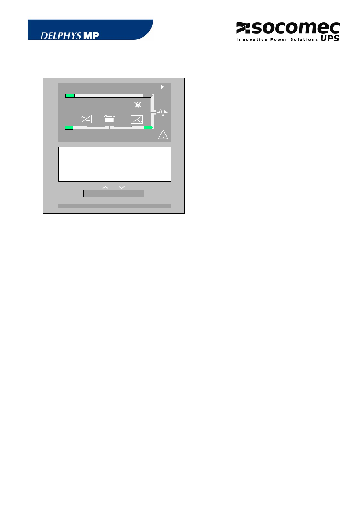
2.3 MIMIC CONTROL PANEL
ESC
The control panel is composed of:
- 1 mimic panel
- 1 eight-line LCD display (with up to 40
characters)
- 1 four-key intuitive user interface:
1 validation key (ENTER)
1 ESC key
2 scrolling keys (UP/DOWN)
- 1 luminous status bar
ENTER
2.3.1 Contrast setting
The display contrast is set by the factory. It is automatically adjusted according to the
temperature of the technical plant. No setting is required.
2.3.2 Luminous status bar
The status bar provides immediate indication about the operating conditions of the system.
The following information can be displayed.
Green bar:
Yellow bar:
Yellow blinking bar:
Red bar:
Red blinking bar:
- the load is supplied via the inverter
- the load is supplied via the bypass path if in Eco-mode
the load is supplied via the automatic / maintenance bypass
maintenance mode or maintenance alarm active
the load is not supplied
the imminent shutdown alarm is given
UPS/NTA GB/DELMP_EXPC1C3C6_B 11
Page 13

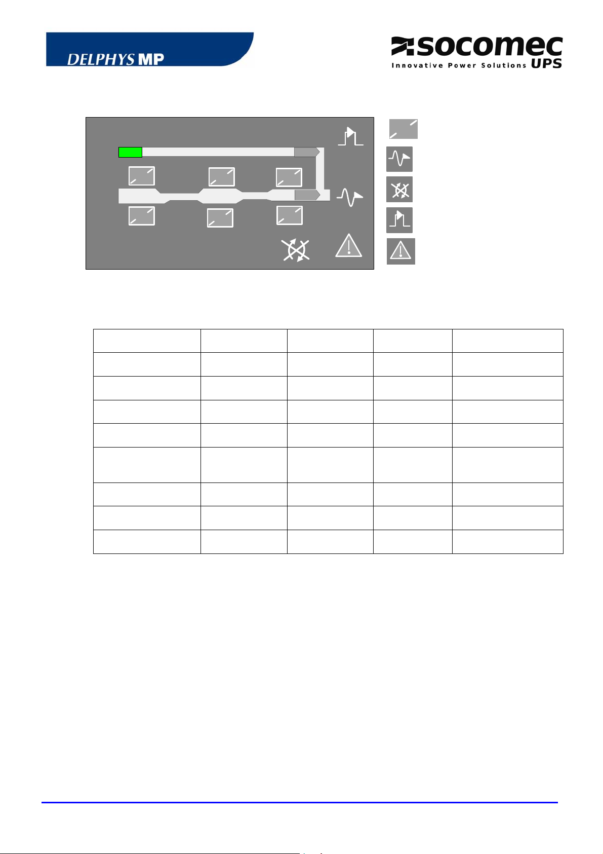
2.4 MEANING OF THE PICTOGRAMS
7
2
10
Rectifier and battery charger
Battery
9
4
3
1
5
6
11
8
Inverter
Output to the loads
Transfer impossible
Maintenance bypass
General alarm
2.4.1 Mimic panel description
SYMBOLS GREEN YELLOW RED BLINKING
1 RECTIFIER INPUT
2 BYPASS INPUT
3 RECTIFIER
4 BATTERY
5 INVERTER
Within
tolerances
Within
tolerances
ON
Charged discharging
ON
Without
tolerances
Without
tolerances
Operating and
alarm ON
Operating and
alarm ON
Green: charging
Yellow: battery alarm
6 LOAD ON INVERTER
7 LOAD ON MAINS
8 LOAD OUTPUT
9 TRANSFER
10 MAINTENANCE BYPASS
11 GENERAL ALARM
OK INV switch ON
If Eco Mode
active
BYP
switch ON
supplied
Impossible
ON
Alarm ON
OFF
Red: imminent stop
Yellow: maint. Byp
alarm
Yellow: communication
error
UPS/NTA GB/DELMP_EXPC1C3C6_B 12
Page 14

2.5 MENU STRUCTURE
From the permanently displayed screen:
Press "ENTER" to reach the various menus,
Select the menu with the UP
Press "ENTER" to reach the various sub-menus,
Select the sub-menu with the UP
Validate with the "ENTER" key.
LIST OF MENUS LIST OF SUB-MENUS
t
MEASUREMENTS "ENTER"4
UPS SYSTEM OUTPUT POWER
BYPASS. – INVERTER MAINS
AUTOMATIC START UP
UPS COMMANDS "ENTER"4
LOAD TO MAINS / LOAD TO INVERTER
ECO MODE PROGRAMMING
OPERATING MODE "ENTER"4
SYSTEM
EVENT LOG "ENTER"4
BATTERY TEST INFORMATION
BATTERY "ENTER"4
BATTERY TEST PROGRAMMING
BATTERY MEASUREMENTS
DIAGNOSTIC CODES
UPS GENERAL "ENTER"4
DATA
UPS SYSTEM STATUS
STATUS "ENTER"4
RECTIFIER ON / OFF
SUBSET "ENTER"4
INVERTER ON / OFF
COMMAND
LOAD ON MAINS / LOAD ON INVERTER
PROGRAMMING
CLOCK "ENTER"4
LANGUAGE
CONFIGURATION "ENTER"4
BUZZER
ACCESS CODE
JBUS LINK "ENTER"4
Load protected by inverter
Load rate:
0
50 100
120
or DOWN key,
or DOWN key,
UPS SYSTEM OUTPUT
RECTIFIER - BATTERY
TRANSFER TO MAINTENANCE BYPASS
TRANSFER TO NORMAL MODE
BATTERY MANUAL TEST
REFERENCES
AUXILIARY INPUTS
SHUTDOWN UPS OUTPUT
LOCAL / REMOTE
PROGRAMMING
Note Controls are only displayed when available.
UPS/NTA GB/DELMP_EXPC1C3C6_B 13
Page 15

2.6 OPERATING A SINGLE UPS
The « UPS COMMANDS » menu is designed for the operation of the UPS.
Note: controls are only displayed when available.
2.6.1 Starting up the UPS
Prior to any operation, please refer to the basic scheme of the system.
Conditions to be completed:
- The system is live,
- wait for the control panels to light up.
Comply with the following chronology procedure:
The UPS is started from the "UPS COMMANDS" menu and the "AUTOMATIC START UP"
sub-menu through an interactive procedure. Just follow the instructions displayed and
validate with the "ENTER" key.
Display for the automatic start up control:
UPS COMMANDS: AUTOMATIC START UP
CONFIRM THE START UP WITH UPS
SYSTEM OUTPUT SWITCHING ON
cancel validate
ESC ENTER
2.6.2 Load transfer from inverter to mains
The load transfer is achieved from the "UPS COMMANDS" menu and the "LOAD TO
MAINS" submenu, which enables the seamless switching from the inverter source to the
non protected bypass source. Validate with the "ENTER" key.
Display for the LOAD TO MAINS control:
SUBSET COMMAND: LOAD TO MAINS
CONFIRM TRANSFER
TO AUTOMATIC BYPASS
cancel validate
'ESC' 'ENTER'
UPS/NTA GB/DELMP_EXPC1C3C6_B 14
Page 16

2.6.3 Load transfer from mains to inverter
The load transfer is achieved from the "UPS COMMANDS" menu and the "LOAD TO
INVERTER" sub-menu, which enables the seamless switching of the load from the bypass
source to the protected inverter source. Validate with the "ENTER" key
Display for the LOAD TO INVERTER control:
UPS COMMAND: LOAD TO INVERTER
CONFIRM TRANSFER TO INVERTER
Cancel validate
'ESC' 'ENTER'
2.6.4 UPS shutdown with transfer to the maintenance bypass
The Maintenance bypass is for ensuring supply to the load, while the system is stopped for
servicing reasons, for instance.
The transfer is achieved from the "UPS COMMANDS" menu and the "TRANSFER TO
MAINTENANCE BYP" sub-menu. This is achieved through an interactive procedure. Just
follow the instructions displayed and validate with the "ENTER" key.
Display for the "TRANSFER TO MAINTENANCE BYP" control:
UPS COMMANDS: TRANSFER TO M. BYPASS
CONFIRM TRANSFER
TO MAINTENANCE BYPASS
cancel validate
ESC ENTER
2.7 OPERATING MODE
Note: the operating mode is displayed only if the configuration is available. Seek advice to the
CIM department.
The UPS can either operate in normal or Eco mode. The mode can be selected manually or
programmed to be made automatically.
Mode normal: the load is supplied by the inverter. Should a problem occur on the rectifier-
inverter path, the load is automatically transferred to the bypass input.
Eco mode: the load is supplied by the bypass input. Should a problem occur on the bypass
path, the load is automatically transferred to the inverter.
UPS/NTA GB/DELMP_EXPC1C3C6_B 15
Page 17

CHAPTER 3: MODULAR SYSTEMS
UPS/NTA GB/DELMP_EXPC1C3C6_B 16
Page 18

3.1 BASIC SCHEMES
Modular systems can include up to six UPS units.
3.1.1 Modular systems with two redundant UPS units
Q5
Q3
Q5
Q3
Q4
Q1
Q4
Q1
MBP
MBP
INV
X20
Q20
*
INV
X10: rectifier input
X40: bypass input
X50: to the load
X20: battery connection
REC: rectifier
INV: inverter
BAT: battery
BP: bypass facility
ABP: automatic bypass
MBP: maintenance bypass
* other protection upon request.
NOTE: in such a configuration each UPS unit
has its own maintenance bypass.
X20
Q20
NOTE: in any case, see the technical details of the drawing.
3.1.2 Modular systems with two non redundant UPS units
MBP Q5
X20
X20
X10: rectifier input
X40: bypass input
X50: to the load
X20: battery connection
REC: rectifier
INV: inverter
BAT: battery
BP: bypass facility
ABP: automatic bypass
MBP: maintenance bypass
* other protection upon request
NOTE: in such a configuration, the system is
fitted with an EXTERNAL maintenance
bypass.
.
NOTE: in any case, see the technical details of the diagram.
UPS/NTA GB/DELMP_EXPC1C3C6_B 17
Page 19

3.1.3 Modular systems with three UPS units or more
MBP Q5
X20
X20
X20
X10: rectifier input
X40: bypass input
X50: to the load
X20: battery connection
REC: Rectifier
INV: Inverter
BAT: battery
BP: bypass facility
ABP: automatic bypass
MBP: maintenance bypass
* other protection upon request.
NOTE: in such a configuration, the system is
fitted with an EXTERNAL maintenance
bypass.
NOTE: in any case, see the technical details of the diagram.
3.2 LAYOUT OF SWITCHES
Description of switches:
Q4: automatic bypass switch
Q3: output switch
Q5: maintenance bypass switch
Note:
Q20: battery protection is located in
the battery cabinet or battery
enclosure.
Q1: rectifier input switch (optional)
Q4 Q5 Q3
UPS/NTA GB/DELMP_EXPC1C3C6_B 18
Page 20

3.3 CONTROL PANEL
ESC
ENTER
The control panel is composed of:
- 1 mimic panel
- 1 eight-line LCD display (with up to 40
characters)
- 1 four-key intuitive user interface:
1 validation key (ENTER)
1 ESC key
2 scrolling keys (UP/DOWN)
- 1 luminous status bar
3.3.1 Contrast setting
The display contrast is set by the factory. It is automatically adjusted according to the
temperature of the technical plant. No setting is required.
3.3.2 Description of the luminous status bar
Green bar:
the load is supplied via the inverter
the load is supplied via the bypass path if the Eco-mode is
activated
Yellow bar:
Yellow blinking bar:
Red bar:
Red blinking bar:
OFF:
the load is supplied via the automatic / maintenance bypass
maintenance mode or maintenance alarm
load OFF
the imminent shutdown alarm is given
UPS unit isolated or not available.
UPS/NTA GB/DELMP_EXPC1C3C6_B 19
Page 21

3.4 MEANING OF THE PICTOGRAMS
2
3
1
3.4.1 Mimic panel description
SYMBOLS GREEN YELLOW RED BLINKING
1 RECTIFIER INPUT
2 BYPASS INPUT
3 RECTIFIER
4 BATTERY
5 INVERTER
7
9
4
5
6
11
Within
tolerances
Within
tolerances
ON
Without
tolerances
Without
tolerances
Operating and
alarm ON
Charged discharging
ON
Operating and
alarm ON
10
Rectifier and battery charger
Battery
8
Inverter
Output to the loads
Transfer impossible
Maintenance bypass
General alarm
Green: charging
Yellow: battery alarm
6 LOAD ON INVERTER
7 LOAD ON MAINS
8 LOAD OUTPUT
9 TRANSFER
10 MAINTENANCE BYPASS
11 GENERAL ALARM
OK Eco-Mode ON
If Eco Mode
ON
BYP
switch ON
supplied
Impossible
ON
Alarm ON
Not supplied
Red: imminent stop
Yellow: Maint. Byp
alarm
Yellow: communication
error
UPS/NTA GB/DELMP_EXPC1C3C6_B 20
Page 22

3.5 STRUCTURE OF THE SYSTEM RELATED MENU
It is intended for operating the whole system, i.e. all the UPS units.
Display information about
UPS SYSTEM
UNIT
Cancel validate
"ESC" "ENTER"
Press "ENTER" to reach the various menus,
Select the menu with the UP
or DOWN key,
Press "ENTER" to reach the various sub-menus,
Select the sub-menu with the UP
or DOWN key,
Validate with the "ENTER" key.
LIST OF MENUS LIST OF SUB-MENUS
t
MEASUREMENTS "ENTER"4
UPS SYSTEM OUTPUT POWER
SYSTEM BYPASS SUPPLY
UPS AUTOMATIC STARTUP
UPS COMMANDS "ENTER"4
LOAD TO MAINS / LOAD TO INVERTER
TRANSFER TO MAINTENANCE BYPASS
ECO MODE PROGRAMMING
OPERATING MODE "ENTER"4
TRANSFER TO NORMAL MODE
UPS
EVENT LOG "ENTER"4
UPS SYSTEM STATUS
STATUS "ENTER"4
PROGRAMMING
CLOCK "ENTER"4
LANGUAGE
CONFIGURATION "ENTER"4
BUZZER
ACCESS CODE
PROGRAMMING
JBUS LINK "ENTER"4
(if available)
u
UPS SYSTEM OUTPUT
LOCAL / REMOTE
Note Controls are only displayed when available.
UPS/NTA GB/DELMP_EXPC1C3C6_B 21
Page 23

3.6 STRUCTURE OF THE UNIT RELATED MENUS (UNIT)
It is only for operating the related unit.
Display information about
UPS SYSTEM
UNIT
Cancel validate
"ESC" "ENTER"
Press "ENTER" to reach the various menus,
Select the menu with the UP
or DOWN key,
Press "ENTER" to reach the various sub-menus,
Select the sub-menu with the UP
or DOWN key,
Validate with the "ENTER" key.
LIST OF MENUS LIST OF SUB-MENUS
MEASUREMENTS "ENTER"4
t
UPS UNIT OUTPUT POWER
INVERTER - BYPASS MAINS
UNIT AUTOMATIC START UP
UNIT COMMANDS "ENTER"4
UNIT COUPLING / UNCOUPLING
UNIT
EVENT LOG "ENTER"4
BATTERY TEST INFORMATION
BATTERY "ENTER"4
BATTERY TEST PROGRAMMING
BATTERY MEASUREMENTS
DIAGNOSTIC CODES
UNIT "ENTER"4
REFERENCES
DATA
UPS UNIT STATUS
STATUS "ENTER"4
RECTIFIER ON / OFF
SUBSET "ENTER"4
INVERTER ON / OFF
COMMANDS
LOAD TO MAINS / LOAD TO INVERTER
u
UPS UNIT OUTPUT
RECTIFIER - BATTERY
BATTERY MANUAL TEST
AUXILIARY INPUTS
UNIT COUPLING / UNCOUPLING
Note Controls are only displayed when available.
UPS/NTA GB/DELMP_EXPC1C3C6_B 22
Page 24

3.7 OPERATING THE MODULAR SYSTEM
Each unit has it’s own control panel. The menu structure is divided into two distinctive parts
(Please, refer to sections
3.5 and 3.6)
- the first one is for operating the system
- the second one is intended for operating the unit.
Note: controls are only displayed when available.
3.7.1 Starting up the modular system
Prior to any operation, please refer to the basic scheme of the system.
Conditions to be completed:
- the system is live on the input of each UPS unit,
- the battery circuit of each UPS unit is open.
- wait for all the control panels to light up,
In the control panel of one of the units, select:
- menu "UPS SYSTEM",
- menu " UPS COMMANDS"
- and submenu "AUTOMATIC STARTUP".
The startup of all the units is run through an interactive procedure. Just follow the
instructions displayed and validate with the "ENTER" key. Pressing the ESC key cancels
the action.
At the end of this stage, the load is protected by the UPS units.
The display indicates the end of the automatic start up procedure:
Load protected by inverter
1 2 3 4 5 6
Load rate:
UNIT 2
0
Number of
operating units
50 100
120
UPS/NTA GB/DELMP_EXPC1C3C6_B 23
Page 25

3.7.2 Load transfer from inverter to mains
In the control panel of one of the units, select:
- menu "UPS SYSTEM",
- menu "UPS COMMANDS"
- and submenu "LOAD TO MAINS".
Display for the "LOAD TO MAINS" control
UPS COMMANDS: LOAD TO MAINS
CONFIRM TRANSFER TO
AUTOMATIC BYPASS
cancel validate
'ESC' 'ENTER'
Validate pressing the ENTER key.
3.7.3 Load transfer from mains to inverter In the control panel of one of the units, select:
- menu "UPS SYSTEM",
- menu "UPS COMMANDS"
- and submenu "LOAD TO INVERTER".
Display for the "LOAD TO INVERTER" control
UPS COMMANDS: LOAD TO INVERTER
CONFIRM TRANSFER TO INVERTER
Cancel validate
'ESC' 'ENTER'
Validate pressing the ENTER key.
UPS/NTA GB/DELMP_EXPC1C3C6_B 24
Page 26

3.7.4 Switching to maintenance bypass - shutdown of the system Purpose:
The Maintenance bypass is for ensuring supply to the load, while the system is stopped for
servicing, for instance.
Comply with the following procedure:
In the control panel of one of the units, select:
- menu "UPS SYSTEM",
- menu "UPS COMMANDS"
- menu "TRANSFER TO MAINTENANCE BYPASS".
The command is run through an interactive procedure. Just follow the instructions
displayed and validate with the "ENTER" key.
Display for "TRANSFER TO MAINTENANCE BYP"
UPS commands: to MAINTENANCE BYPASS
CONFIRM LOAD TRANSFER
TO MAINTENANCE BYPASS
cancel validate
ESC ENTER
NOTE: when the process is completed, all the UPS units are stopped.
Do not forget that even when the loads are stopped the units are live:
- because of the utility voltage to the rectifier and the bypass.
CAUTION
- because of the residual voltage of the capacitors.
- because of the load voltage when the maintenance bypass Q5 is closed
and the bypass supply is present.
3.7.5 System with two redundant units
In a system with two redundant units, only one maintenance bypass can be closed.
3.7.6 System with two non redundant units or more than two parallel units
In such a system, the maintenance bypass is common to the whole system.
UPS/NTA GB/DELMP_EXPC1C3C6_B 25
Page 27

3.7.7 Uncoupling of a unit
CAUTION
The uncoupling of a unit is to be made from its control panel by selecting:
- the menu "UPS UNIT"
- the menu "UNIT COMMANDS"
- and the submenu "UNIT UNCOUPLING".
At this point, the UPS unit is uncoupled but still operating. Open switch Q3 in the
appropriate unit to isolate it from the system.
Note: At this point, the UPS unit can be autonomously operated.
Unit uncoupling can only be achieved if the system is redundant,
meaning that it can supply all the energy required to the load with
one unit disconnected.
3.7.8 Shutdown of a unit
(The unit has been previously uncoupled - See section
Shutdown the unit in the following chronology order:
- select the menu "SUBSET COMMAND"
- select the submenu "INVERTER OFF",
- select the submenu "RECTIFIER OFF"
At this point:
- open battery protection Q20,
- open switch Q4
- open switch Q1 (if provided).
Do not forget that even when the load is stopped the unit is live:
- because of the mains voltage to the rectifier and the bypass.
CAUTION
- because of the residual voltage of the capacitors.
- because of the load voltage coming from the common busbar
(downstream of Q3).
3.7.7)
UPS/NTA GB/DELMP_EXPC1C3C6_B 26
Page 28

3.7.9 Unit switching on or coupling to the common busbar Conditions to be completed:
- the system is live upstream of the UPS unit
- wait for the control panel to light up.
In the control panel of the appropriate unit, successively select:
- the menu "UPS UNIT"
- the menu "UNIT COMMANDS"
- and the submenu "AUTOMATIC STARTUP".
The automatic startup is run through an interactive procedure. Just follow the instructions
displayed and validate with the "ENTER" key.
Note: at the end of the start up sequence, the unit is coupled to the common busbar and
Q3 is closed.
UPS/NTA GB/DELMP_EXPC1C3C6_B 27
Page 29

CHAPTER 4: CENTRAL BYPASS SYSTEMS
UPS/NTA GB/DELMP_EXPC1C3C6_B 28
Page 30

X
4.1 STANDARD BASIC SCHEME
Central bypass systems can include up to six modules in parallel.
X40
REC INV
X10
REC INV
X10
REC INV
MBP
ABP
X20
X20
BP
50
X10: rectifier input
X40: bypass input
X50: to the load
REC: rectifier
INV: inverter
BAT: battery
BP: bypass facility
ABP: automatic bypass
MBP: maintenance bypass
* other protection upon request
X10
X20
NOTE: in any case, see the technical details of the drawing.
4.2 LAYOUT OF SWITCHES
UPS UNIT BYPASS CABINET
Q4
Q5
Q3
Q2: Unit output switch
Q20: Battery protection in the battery
enclosure or cabinet
Q4: Input automatic bypass switch
Q3: Output switch to the load
Q5: Maintenance bypass switch
Q1: Input rectifier switch (optional)
UPS/NTA GB/DELMP_EXPC1C3C6_B 29
Page 31

4.3 CONTROL PANELS
CONTROL PANEL OF THE MODULE
CONTROL PANEL OF THE BYPASS CABINET
Each control panel is composed of:
- 1 mimic panel
- 1 eight-line LCD display (with up to 40
characters)
- 1 four-key intuitive user interface:
1 validation key (ENTER)
1 ESC key
2 scrolling keys (UP/DOWN)
- 1 luminous status bar.
The display contrast is set by the factory. It
is automatically adjusted according to the
temperature of the technical plant. No setting
is required.
UPS/NTA GB/DELMP_EXPC1C3C6_B 30
Page 32
4.4 MIMIC PANEL OF THE CENTRAL BYPASS CABINET
3
1
1
4
2
5
3
2
6
5
7
4.4.1 Mimic panel description
1
modules 1 to 6
6
4
General output to the loads
Transfer impossible
Maintenance bypass
General alarm
SYMBOLS GREEN YELLOW RED BLINKING
MODULES 1 to 6
1. BYPASS INPUT
2. LOAD ON
INVERTER
3. LOAD ON MAINS
4. OUTPUT TO THE
LOAD
5. LOAD TRANSFER
6. MAINTENANCE BYP
7. GENERAL ALARM
Connected
Within tolerances
OK Eco-mode active
If ECO MODE
active
supplied
impossible
ON
Connected and
alarm active
Without
tolerances
BYP
switch ON
At least one
alarm ON
Load not
supplied
4.4.2 Description of the luminous status bar on the central bypass cabinet
Green bar:
- the loads are protected by the inverters
- the loads are supplied via the bypass input if in Eco-mode
- the system operates in the "Energy Saver" mode
(i.e. the number modules ON depends on the energy required)
Red: imminent
shutdown of the
system
Yellow: Maint. byp
alarm
Yellow: communication
error
Yellow bar:
- the loads are supplied via the bypass input
- the loads are supplied via the maintenance bypass
Yellow blinking bar:
- maintenance mode or maintenance alarm active
Red bar:
Red blinking bar:
- the loads are not supplied
- the imminent shutdown alarm is given and the loads will shortly
be disconnected.
UPS/NTA GB/DELMP_EXPC1C3C6_B 31
Page 33

4.4.3 Structure of the menus on the central bypass cabinet
Load protected by inverter
1 2 3 4 5 6
Load rate:
0
50 100
Press "ENTER" to reach the various menus,
Select the menu with the UP
or DOWN key,
Press "ENTER" to reach the various sub-menus,
Select the sub-menu with the UP
or DOWN key,
Validate with the "ENTER" key.
LIST OF MENUS LIST OF SUB-MENUS
t
MEASUREMENTS "ENTER"4
UPS SYSTEM OUTPUT POWER
UPS AUTOMATIC START UP
UPS COMMANDS "ENTER"4
LOAD TO MAINS / LOAD TO INVERTER
TRANSFER TO MAINTENANCE BYPASS
UPS
EVENT LOG "ENTER"4
UNIT
DIAGNOSTIC CODES
BYPASS DATA "ENTER"4
REFERENCES
UPS SYSTEM STATUS
STATUS "ENTER"4
LOAD TO MAINS / LOAD TO INVERTER
SUBSET COMMAND
SHUTDOWN UPS OUTPUT
"ENTER"4
PROGRAMMING
CLOCK "ENTER"4
LANGUAGE
CONFIGURATION "ENTER"4
BUZZER
ACCESS CODE
PROGRAMMING
JBUS LINK "ENTER"4
u
UPS SYSTEM GENERAL OUTPUT
INVERTER / BYPASS MAINS
LOCAL / REMOTE
120
Note Controls are only displayed when available.
UPS/NTA GB/DELMP_EXPC1C3C6_B 32
Page 34

4.5 MIMIC PANEL OF A MODULE
2
1
4.5.1 Mimic panel description
Rectifier and battery
charger
3
4
6
5
7
Battery
Inverter
Module output to the
common busbar
General alarm
SYMBOLS GREEN YELLOW RED BLINKING
1. RECTIFIER INPUT
2. RECTIFIER
3. BATTERY
4. INVERTER
5. OUTPUT SWITCH
6. OUTPUT TO THE
COMMON BUSBAR
7. GENERAL ALARM
Within
tolerances
ON Alarm ON
Charged discharging
ON Alarm ON
Closed
Module
connected
Without
tolerances
Closed and
Eco-Mode ON
General alarm ON
4.5.2 Description of the luminous status bar on a module
Green bar:
the module is connected to the common busbar
Module not
connected
Green: charging
Yellow: battery alarm
Red: imminent stop
Communication error
Yellow bar:
the load is supplied via the automatic or the maintenance
bypass
Yellow blinking bar:
Red bar:
Red blinking bar:
OFF
maintenance mode or maintenance alarm active
the load is not supplied
the imminent shutdown alarm is given for the module
Module isolated
UPS/NTA GB/DELMP_EXPC1C3C6_B 33
Page 35

4.5.3 Structure of the Unit menus
Load protected by inverter
1 2 3 4 5 6
Load rate:
Module 1
Press "ENTER" to reach the various menus,
Select the menu with the UP
Press "ENTER" to reach the various sub-menus,
Select the sub-menu with the UP
Validate with the "ENTER" key.
LIST OF MENUS LIST OF SUB-MENUS
MEASUREMENTS "ENTER"4
t
UPS UNIT OUTPUT POWER
INVERTER – BYPASS MAINS
UNIT AUTOMATIC START UP
UNIT COMMANDS "ENTER"4
UNIT COUPLING/UNCOUPLING
UNIT
EVENT LOG "ENTER"4
BATTERY TEST INFORMATION
BATTERY "ENTER"4
BATTERY TEST PROGRAMMING
BATTERY MEASUREMENTS
DIAGNOSTIC CODES
UPS GENERAL "ENTER"4
UPS REFERENCES
DATA
UPS UNIT STATUS
STATUS "ENTER"4
AUXILIARY INPUTS
RECTIFIER ON / OFF
SUBSET "ENTER"4
INVERTER ON / OFF
COMMANDS
LOAD TO MAINS / LOAD TO INVERTER
u
0
50 100
120
or DOWN key,
or DOWN key,
UPS UNIT OUTPUT
RECTIFIER - BATTERY
BATTERY MANUAL TEST
UNIT COUPLING / UNCOUPLING
Note Controls are only displayed when available.
UPS/NTA GB/DELMP_EXPC1C3C6_B 34
Page 36

4.6 OPERATING THE CENTRAL BYPASS SYSTEM
4.6.1 Using
The central bypass cabinet has a control panel intended for the operation of the system,
while the one on the modules is only dedicated to the operation of the relevant module.
4.6.2 Preliminary conditions
- Q4, Q5 and Q3 in the central bypass cabinet are open,
- Q1 (if provided), Q2 and Q20 of each module are open.
4.6.3 Starting up the system
Prior to any operation, please refer to the basic scheme of the system.
Conditions to be completed:
- the input of the system is live
- wait for all the control panels to light up.
In the central bypass cabinet:
The UPS is started from the menu "UPS COMMANDS /AUTOMATIC START UP" through
an interactive procedure. Just follow the instructions displayed and validate with the
"ENTER" key. The action can be interrupted by pressing the "ESC" key.
The display indicates the end of the automatic start up procedure:
Load protected by the inverter
1 2 3 4 5 6
Load rate:
0
50 100
Number of
operating units
120
UPS/NTA GB/DELMP_EXPC1C3C6_B 35
Page 37

4.6.4 Load transfer from inverter to mains In the central bypass cabinet:
The seamless transfer command from inverter to mains can be achieved from the menu
"UPS COMMANDS" and the submenu "LOAD TO MAINS". Validate with the "ENTER" key.
Display for the "LOAD TO MAINS" control
UPS COMMANDS: LOAD TO MAINS
CONFIRM TRANSFER TO AUTOMATIC BYP
cancel validate
'ESC' 'ENTER'
4.6.5 Load transfer from mains to inverter In the central bypass cabinet:
The seamless load transfer from mains to inverter can be achieved in the menu "UPS
COMMANDS" and the submenu "LOAD TO INVERTER". Validate with the "ENTER" key.
Display for the "LOAD TO MAINS" control
UPS COMMANDS: LOAD TO INVERTER
CONFIRM TRANSFER TO INVERTER
Cancel validate
'ESC' 'ENTER'
4.6.6 UPS shutdown with switching to the maintenance bypass In the central bypass cabinet:
The transfer to maintenance bypass should be carried out by selecting the menu "UPS
COMMANDS" and the submenu "TRANSFER TO MAINTENANCE BYPASS". This control
is run through an interactive procedure. Just follow the instructions displayed and validate
with the "ENTER" key.
In each module:
- follow the instructions given on the control panel.
- successively shutdown the rectifiers (open Q1 if provided).
Note: at this stage the load is supplied by the maintenance bypass (no protection) and the
modules are stopped.
UPS/NTA GB/DELMP_EXPC1C3C6_B 36
Page 38

4.6.7 Operating a module of the system
Module uncoupling can only be achieved if the system is
redundant, meaning that it can supply all the energy required
to the load with one module disconnected.
4.6.7.1 Uncoupling of a module
The uncoupling of a module is to be made from its control panel by selecting:
- the menu "UNIT COMMANDS"
- the submenu "UNIT UNCOUPLING" ("cancel" is being displayed)
- press key
- press key ENTER to confirm the request
- open switch Q2
to reach the module uncoupling option
4.6.7.2 Shutdown of a module
In the control panel of the appropriate module, select:
- the menu "SUBSET COMMAND"
- the submenu "INVERTER OFF" and confirm with the ENTER key
- the submenu "RECTIFIER OFF" and confirm with the ENTER key
- open Q1 (if provided) and Q20 (battery protection),
Note 1: operations are identical for all modules.
Note 2: in case of a redundant system, the command is inhibited if the module
uncoupling causes the loss of redundancy; the corresponding alarm is displayed
on the central bypass cabinet.
Do not forget that even when the load is stopped the module is
live:
- because of the input voltage upstream of Q1,
CAUTION
- because of the load voltage coming from the common busbar
downstream of Q2,
- because of the continuous voltage generated by the
capacitors. The safety level is only reached after 5 minutes.
4.6.8 Starting and coupling a module
The startup of the modules is run through an interactive procedure.
In the control panel of the module:
- select the menu "UNIT COMMANDS"
- select the submenu " UNIT AUTOMATIC STARTUP"
- confirm with the ENTER key
- comply with the instructions displayed i.e.:
- close Q1 (if provided) to supply the rectifier
- validate startup with the battery before closing Q20
- close Q2.
Note 1: operations are identical for all modules.
At this point, the module is connected to the common busbar.
UPS/NTA GB/DELMP_EXPC1C3C6_B 37
Page 39

CHAPTER 5: DESCRIPTION OF THE MENUS
UPS/NTA GB/DELMP_EXPC1C3C6_B 38
Page 40

5.1 LCD DISPLAY
Various screens can be displayed:
- the permanent display by default
B
A. The load supply source is displayed, i.e.:
B. The actual alarms are displayed as long as they have not been reset by the operator (or auto-
reset).
C. The load rate is displayed as long as less than 4 alarms are not activated.
Note:
if the icon is displayed, some maintenance has to be planned.
- The menu screen
A
Load protected by inverter
Load rate:
0
50 100
C
LOAD PROTECTED BY INVERTER,
LOAD SUPPLIED BY AUTOMATIC BYPASS,
LOAD SUPPLIED BY MAINTENANCE BYPASS,
OPERATING ON BATTERY,
LOAD OFF,
D
E
MEASUREMENTS AUTOMATIC STARTUP
UPS COMMANDS LOAD TO MAINS
OPERATING MODE TRANSFER TO MAINTENANCE BYP
EVENT LOG ↓
D. The menus available are displayed.
E. The submenu related to the selected menu is highlighted on the display.
Note: the remaining displays are described in the corresponding paragraphs.
UPS/NTA GB/DELMP_EXPC1C3C6_B 39
Page 41

5.2 COMMENTS CONCERNING THE MENUS
5.2.1 Menu measurements
This menu displays the following system measurements:
- general measurements of the UPS
- output power of the UPS,
- inverter and bypass measurements,
- rectifier measurements.
5.2.2 Menu UPS commands
The UPS commands menu enables (Please refer to the sections related to the menu
structure):
- the automatic start up (interactive procedure)
- the transfer from the inverter to the mains (and vice-versa),
- the transfer to the maintenance bypass (interactive procedure),
Note: in the event of a modular system, the UPS COMMANDS menu is common to all the
modules connected. The control can be performed on whatever module.
5.2.3 Menu Event log
Principle:
The UPS has a memory enabling the record and date all alarms, status or commands that
could arise during operation. This memory is saved utilising a separate supply.
The log can record up to 500 items according to the FIFO principle (First In - First out).
When the log is filled up, the latest information recorded overwrites the earliest one.
Use:
To improve the user-friendliness, the latest records of the relevant date are displayed over
six lines. Press key
next line. The "ENTER" key provides access to the previous days.
EVENT LOG
05/12/2005
15:19:45 Unit overload yes
15:19:30 Load protected by inverter yes
15:19:20 Load on automatic bypass yes
15:19:05 Inverter ON yes
15:15:35 Battery charging yes
15:15:28 Charger ON yes ↓
↓ indicates other messages are stored. Press key
information.
or to respectively scroll up to previous line or scroll down to
to have access to the previous
UPS/NTA GB/DELMP_EXPC1C3C6_B 40
Page 42

5.2.4 Battery
The battery test is for controlling the battery capacity to supply energy. The battery test can
either be made manually or automatically.
5.2.4.1 Battery test information
This menu provides information to show:
- the result of the latest battery test (OK, failed or aborted),
- date and time of the latest battery test,
- date and time of the next battery test. If the test is not scheduled, "----" is
displayed instead of the date.
5.2.4.2 Test programming
The battery test can be made automatic from the control panel by setting the
frequency, the day of the week and the time.
BATTERY: BATTERY TEST PROGRAMMING
BATTERY TEST: inactive
PROGRAMMED ON: Friday at 20:00
EVERY: 8 weeks
5.2.4.3 Battery measurements
The following measurements can be displayed:
- Battery voltage,
- Battery current (minus sign in front of the value means the battery is
discharging)
- Battery temperature,
- Load rate.
BATTERY MEASUREMENTS
Vdc = 450 V I batt = - 56 A
Load rate :
UPS/NTA GB/DELMP_EXPC1C3C6_B 41
Page 43

5.2.5 UPS system data
5.2.5.1 Diagnostic codes
All basic information can be displayed in a single screen thanks to hexadecimal
codes.
UPS SYSTEM DATA: DIAGNOSTIC CODES
User Status Alarms
Adv Rect 120000456087 000000000
Adv Byp 000657003300 000007650
Adv Inv 000765876000 006549800
Adv Hmi 076431789700 054687900
Adv Com 000006757400 000007650
In case of UPS failure, the customer can transmit these codes to the CIM
DEPARTMENT for complete diagnostic.
5.2.5.2 UPS references
This menu displays the following module information:
- module number,
- serial number,
- power in kVA.
5.2.6 Status menu
5.2.6.1 List of status
The activation or de-activation of each state is confirmed by YES or NO.
By means of the up and down keys, you can scroll the list.
Symbol
at the end.
is not displayed at the beginning of the list and is not displayed
UPS/NTA GB/DELMP_EXPC1C3C6_B 42
Page 44

List of STATUS
Wording
Rectifier ON
Rectifier input supply out of tolerances
Charger ON
Boost charge
Commissioning charge
Synchronisation reference on bypass input
Synchronisation reference on ACS
Battery charging
Battery charged
Battery test aborted
Battery test running
Inverter ON
ACS functioning forced
Output on inverter
Output on automatic bypass
Output not supplied
Output on maintenance bypass
In eco mode
Transfer to eco mode
Bypass input supply out of tolerances
Bypass input absent
Inverter switch ON
Bypass switch ON
Unit available
Unit isolated
Q2 closed
Q3 closed
Maintenance bypass Q5 closed
General maintenance bypass closed
Q21 …..Q22 closed
ESD activated
Input supplied by EmSet (emergency set)
Maintenance mode active
Load protected by inverter
Load on automatic bypass
Load OFF
Load on maintenance bypass
Automatic start in progress
Transfer to maintenance bypass
Energy saver activated (parallel system with central bypass)
Unit in standby mode
Automatic start forced
Energy saver deactivated (parallel system with central bypass)
Local/remote control
Auxiliary inputs 1 to 12
UPS/NTA GB/DELMP_EXPC1C3C6_B 43
Page 45

5.2.7 Clock
The UPS is fitted with a clock that enables the time and date of every event to be known.
The clock can only be set from the control panel.
I PROGRAMMING
I
I FRIDAY 09:09:21
I
I
I 30/05/2005
I
CLOCK I
The "ENTER" key is for selecting the field to be modified.
The "ESC" key is for returning to the previous field.
The scrolling keys
or is for changing the parameters of the selected field.
5.2.8 Configuration
5.2.8.1 Language
Two languages are available on the control panel.
CONFIGURATION:LANGUAGE
t
Language: FRENCH
u
cancel validate
ESC ENTER
The scrolling keys
Note: other languages can be downloaded by the Servicing Department.
5.2.8.2 Buzzer
The buzzer can be activated or de-activated when the alarm appears by means
of the scrolling keys
CONFIGURATION:BUZZER
t
Buzzer: YES
u
cancel validate
ESC ENTER
or enable the user to select the appropriate language.
or . The buzzer is activated by default.
UPS/NTA GB/DELMP_EXPC1C3C6_B 44
Page 46

5.2.8.3 Access code
The access code enables to lock the access to the following menus:
- UPS COMMANDS,
- OPERATING MODE,
- BATTERY / BATT TEST PROGRAMMING,
- SUBSET COMMAND,
- CLOCK,
- CONFIGURATION,
- JBUS LINK.
CONFIGURATION: ACCESS CODE
Type new access code:??????
This code can only be set from the control panel. It can contain up to 6
characters from "A" to "Z" and "0" to "9".
Keys
or enable to select the character.
The "ENTER" key is for entering the character selected.
The "ESC" key enables to return to the previous field.
For coding with less than 6 characters, the ENTER key needs to be pressed up
to the sixth character, and once more for validation.
CONFIGURATION: ACCESS CODE
CONFIRM NEW
ACCESS CODE: ??????
cancel validate
ESC ENTER
Note: the access code is only activated when the display is in standby, i.e. after 4
minutes without action on any key.
UPS/NTA GB/DELMP_EXPC1C3C6_B 45
Page 47

5.2.9 JBUS link
5.2.8.4 Local / Remote
The UPS can be connected to a remote equipment. By default the control panel
has the master function while the remote control has the slave function (all
controls are inhibited). Through this menu, controls can be sent from the remote
equipment.
CONFIGURATION:LOCAL-REMOTE
t
LOCAL CONTROL
u
cancel validate
ESC ENTER
Note: the JBUS link menu is only displayed if the setting is available on the UPS.
Configuration parameters are:
- the baudrate (1200 to 19200),
- the parity (none, even, odd),
- the slave number (001 to 255).
I PROGRAMMING 1
I
I baudrate: 19200
I
I Parity: NONE
I
I Slave: 001
JBUS LINK I
If a second JBUS link is available, the corresponding screen is automatically displayed
after completing the setting of the first JBUS link.
UPS/NTA GB/DELMP_EXPC1C3C6_B 46
Page 48

5.2.10 List of alarms
5.2.10.1 Display of activated alarms
5.2.10.2 Resetting an alarm
5.2.10.3 List of alarms for single units and modular systems
When an alarm is activated, the description is displayed and an audible signal is
given.
The alarms can be reset by means of the "ENTER" key. Thus, the audible alarm
is silenced, but its description remains displayed as long as the alarm is
activated. If several alarms are displayed, each of them needs to be silenced
individually.
Wording
Rectifier critical alarm
Rectifier preventive alarm
Charger general alarm
Battery alarm
Battery room alarm
Battery test failed
Battery circuit open
Operating on battery
Battery autonomy end
Battery discharged
Inverter critical alarm
Inverter preventive alarm
Bypass critical alarm
Bypass preventive alarm
Manual/automatic transfer disabled
Automatic transfer disabled
Maintenance bypass alarm
Backfeed protection open
Unit imminent stop
Unit overload
Insufficient resources
Synchronisation reference ACS absent
Control preventive alarm
Control alarm
Internal temperature alarm
Loss of redundancy
Unit general alarm
Load imminent stop
Servicing preventive alert
UPS overload alarm
Control panel alarm
UPS/NTA GB/DELMP_EXPC1C3C6_B 47
Page 49

5.3 OVERLOAD MONITORING
Principle:
The UPS overload monitoring is based on reference levels (the higher the load rate, shorter the
overload capacity). There are two distinct reference levels:
- the first one corresponds to the overload capacity of the bypass input,
- the second one corresponds to the overload capacity of the inverter.
While operating from the inverter, the load is automatically transferred to the automatic bypass
when the overload capacity reaches 50% and the bypass input is present.
Signalling and automatic actions:
The UPS OVERLOAD alarm is activated if:
- the load rate exceeds 103% ("LOAD ON INVERTER"),
- the load rate exceeds 105% ("LOAD ON MAINS").
The alarm disappears if the load rate drops below 100%
Typical unit overload < 30°C
Overload rate Inverter and byp
110% 60 minutes 60 minutes 30 min + 60 min
125% 10 minutes 10 minutes 5 min + 10 min
150% 1 minute 1 minute 30 sec + 1 min
NOTE: Should an extended overload occur, the static switch warms up, which results in the
disconnection of the load after some time.
If the load is supplied by the bypass input following an automatic transfer, no return to the
inverter is possible as long as the UPS is overloaded and the UPS OVERLOAD alarm has not
been reset.
Automatic bypass Total overload time
locked
inverter + automatic byp
5.4 REMAINING BACK UP TIME
The remaining back up time is displayed on the control panel when the UPS operates from the
battery. The calculation is obtained from the battery capacity and the Ampères per hour (Ah)
consumed by the load.
Text displayed can be set by Commissioning, Inspection and Maintenance Department.
UPS/NTA GB/DELMP_EXPC1C3C6_B 48
 Loading...