

Page 1

CONTROLLER
ATyS C40
Notice d’utilisation - Operating instructions
F
GB
SOCOMEC GROUP SWITCHING PROTECTION & UPS
MAKE YOUR BUSINESS SAFE
Page 2

SOCOMEC - Réf.: 532 929 B
2
THE A
TyS RANGE _______________________________35
GENERAL PRESENTATION _______________________36
Product introduction ____________________________36
INSTALLATION __________________________________37
Mounting _____________________________________37
Dimensions ___________________________________37
Characteristics_________________________________37
CONNECTIONS _________________________________38
Control circuits_________________________________38
OPERATION ____________________________________42
Presentation___________________________________42
Operational modes _____________________________43
Programming __________________________________44
Operation _____________________________________56
Visualisation ___________________________________60
Automatic sequences ___________________________62
TROUBLESHOOTING GUIDE _____________________64
Summary
GB
Page 3

35
SOCOMEC - Réf. : 532 929 B
The ATyS family proposes a complete motorised
changeover range including electrical and mechanical
interlocking. Manual operation is always possible on all
the products in case of emergency.
The electric command is realised via a motorised
module, electronically driven by 2 types of logic:
• Remote controlled: ATyS 3 products are controlled by
volt free contacts allowing the switch to be driven in 1,
0 or 2 position. These contacts can come from an
external control logic.
• Automatic control: AtyS 6 products integrate all
controls, timers and relays required to realise a
Normal/ Emergency application.
ATyS 6e and 6m versions also integrate the remote
controlled feature.
The motorised and control modules can easily be
replaced without disconnecting the power cables.
Controller
ATyS
THE
ATyS
RANGE
>
This instruction manual applies to following
product:
• Controller ATyS C40
>
Following products are delivered with their own
instruction manual:
• ATyS 3s
• ATyS 3e, 6e
• ATyS 6m
• Remote interfaces ATyS D10 & D20
• ATyS C20/ C30 controller
For personnel and product safety, please
read the contents of these operating
instructions carefully before connecting.
ATyS 3s ATyS 3e ATyS 6e ATyS 6m ATyS C30 ATyS C20 ATyS C40
MOTORISED CHANGEOVER
Dual power supply
Metering
Changeover controller Dual gensetIntegrated control relay
Communication optionCom option
2 I/2 O option
2 inputs / 2 outputs option
Remote interfaces ATyS D10 & D20
Page 4

Product introduction
Controller
ATyS
GENERAL PRESENTATION
ATyS C40
36
SOCOMEC - Réf. : 532 929 B
>
ATyS C40
LCD
Voltage sensing and
power supply terminals
Keypad
Control terminals Modular frame
ATYS 466 B
Page 5

Mounting
>
Mounting rail DIN
Dimensions
Characteristics
37
SOCOMEC - Réf. : 532 929 B
Controller
ATyS
INSTALLATION
ATyS C40
>
IP
IP2 and class II on front face
>
Operation
• Temperature: -20 °C to +60 °C
• Humidity: 80 % at 55 °C
95% at 40 °C
>
Consumption
7.5 VA max
>
Measurement category
Cat III
ATYS 528 B
106
26,5
48
58
90
93
45
62
ATYS 529 A
Page 6

Control circuits
400 Vac (P-P) APPLICATION WITH NEUTRAL CONDUCTOR
SWITCHING TYPE TECHNOLOGY
Controller
ATyS
CONNECTIONS
ATyS C40
38
SOCOMEC - Réf. : 532 929 B
13 14 23 24 33 34 43 44 53 54
CA1
+-
CA2
I1I3 I2
301 302 303 304305 306
DC-
DC+
103
F1, F2
Fuse protection
230 Vac 5 A
205
L3
203
L1
106
L1
105104
L3
III
0C
O1
L1
L2
L3
GE1
N
L1
L2
L3
N
F2F1
LOAD
Ph
Double power
Supply option
Power
230 Vac
Control
N
N
DPS
GE2
ATYS 467 B GB
• Configure the type of control logic in impulse mode
(see Programming chapter).
Maximum control cables lenght = 10 m.
In case of longer distance, insert control
relays.
Page 7

Controller ATyS
CONNECTIONS
39
SOCOMEC - Réf. : 532 929 B
Control circuits
400 Vac (P-P) APPLICATION WITH NEUTRAL CONDUCTOR
CONTACTOR TYPE TECHNOLOGY
I1I3 I2
F1, F2
Fuse protection
230 Vac 5 A
LOAD
III
O1
L1
L2
L3
N
L1
L2
L3
N
F2F1
K1
K1
K2
K1
K2
K2
13 14 23 24 33 34 43 44 53 54
+-
301 302 303 304305 306
DC-
DC+
103 205
L3
203
L1
106
L1
105104
L3
GE1
NL2
GE2
ATYS 468 B GB
• Configure the type of control logic in contactor (see
Programming chapter).
Maximum control cables lenght = 10 m.
In case of longer distance, insert control
relays.
Page 8

Controller
ATyS
CONNECTIONS
ATyS C40
40
SOCOMEC - Réf. : 532 929 B
Control circuits
400 Vac (P-P) APPLICATION WITH NEUTRAL CONDUCTOR
CIRCUIT BREAKER TYPE TECHNOLOGY
>
Electrical interlocking via external control relays
13 14 23 24 33 34 43 44 53 54
I1I3 I2
301 302 303 304305 306
103
F1, F2
BRE. 1
Closing
POS 1
Opening
POS 2
BRE. 2
Fuse protection
230 Vac 5 A
LOAD
205
L3
203
L1
106
L1
105
L2
104
L3N
III
O1
L1
L2
L3
N
L1
L2
L3
N
F2F1
K1
K1
K2
K1
DC-
DC+
K2
K2
1 2
Closing
POS 2
Opening
POS 1
+-
ATYS 530 B GB
Maximum control cables lenght = 10 m.
In case of longer distance, insert control
relays.
* Only on DC versions.
• Configure the type of control logic in contactor (see
Programming chapter).
Page 9

Controller ATyS
CONNECTIONS
41
SOCOMEC - Réf. : 532 929 B
Control circuits
Denomination
Terminals
Description Characteristics
Recommended
section
Power supply L3 (104) Phase 3 440 V ac (phase-phase) 1.5 mm
2
Source L1 (106) Phase 1 maximum, 50/ 60 Hz
Power supply L1 (203) Phase 1 440 V ac (phase-phase) 1.5 mm
2
Source L3 (205) Phase 3 maximum, 50 / 60 Hz
Power supply DC
DC- Power supply 0 V From 9 V dc to 30 V dc 1.5 mm
2
12Vdc, 24Vdc
DC+ Power supply + V dc maxi.
Genset 13 Genset start/ stop relay - 2 stable positions Dry contact 1.5 mm
2
start signal
(1)
14 Programmable state - factory setting = NO, close to start 5A AC1/250 V
Control 23 Impulse mode: order to close source 5 A AC1/ 250 V
(impulse, 24 Contactor mode: order to close contactor source
contactor Breaker mode: order to close breaker source
and breaker 33 Impulse mode: order to close source 5 A AC1/ 250 V 1.5 mm
2
mode to 34 Contactor mode: order to close contactor source
programm) Breaker mode: order to open breaker source
43 Impulse mode: order to close position 0 5 A AC1/ 250 V 1.5 mm
2
44 Contactor mode: programmable relay O1
Breaker mode: order to close breaker source
Genset 53 Genset start/ stop relay - 2 stable positions 5 A AC1/ 250 V 1.5 mm
2
start signal
(1)
54 Programmable state - factory setting = NO, close to start
Information 301 Auxiliary contact information position 1 CA1 Do not connect to 1.5 mm
2
auxiliary 302 Programmable input 3 any power supply
contacts 303 Auxiliary contact information position 2 CA2
Programmable 304 Programmable input 1 Do not connect to 1.5 mm
2
Inputs 305 Programmable input 2 any power supply
Common 316 Specifique voltage supply Do not connect to 1.5 mm
2
input Common terminals 301 to 310 any power supply
(1) Refer to programming, Setup, to modify relay state.
22
2
1
2
2
1
1
1
11
2
1
Page 10

Presentation
The product allows:
• sources control,
• automatic transfer control in AUT mode,
• parameters configuration,
• voltage and frequency metering,
• system state display,
• alarm or fault indication,
Controller
ATyS
OPERATION
ATyS C40
42
SOCOMEC - Réf. : 532 929 B
Presentation
Operational modes
Programming
Operation
Visualisation
Automatic sequences
7 digits + 14 pointers
LCD
Green led is on when product is
powered
POWER led
Led is on when product is faulty.
Disconnect power supplies to reset
FAULT led
- Led is on: source = OK
- Led is off: source is not available
- Led is blinking: order to start is running
Sources state
2 green leds:
- switch I state
- switch II state
Switch state
- Active source: to force the next active source
- Partial counter reset
- Genset remote start (test of load)
Operational modes
Keypad
Escape Navigation
Validation
LCD & leds test
Operations
ATYS 469 A GB
Page 11

Presentation
Controller ATyS
OPERATION
43
SOCOMEC - Réf. : 532 929 B
SOFTWARE VERSION
Displayed after reset.
(3 minutes power off action to allow reset).
Version
number
ATYS 428 A GB
Operational modes
VISUALISATION
Measured values & parametered timers display. Always
accessible without code.
PROGRAMMING
Parameters configuration. Password access (code 1000
from factory).
OPERATION
Test sequences. Password access (code 4000).
Page 12
Programming
Controller
ATyS
OPERATION
ATyS C40
44
SOCOMEC - Réf. : 532 929 B
Presentation
Operational modes
Programming
Operation
Visualisation
Automatic sequences
• This mode allows product parameters configuration
• Always accessible in mode (when programmed on
an input)
• Always accessible in AUT mode, changeover switch on
priority source, priority source being available
• Not accessible when “test off load”, “test on load”
functions are active or during automatic sequence.
Parameters requiring programming before
use:
• type of network
• nominal voltage
• nominal frequency
• control logic
• number of auxiliary contact.
>
Navigation in the menus
• Parameters access: Press “up”, “down”, “left” & “right” push buttons
• Parametermodification: press “left” & “right” push button to access the parameter to modify
Press “up’’ and “down” push buttons to modify the parameter
and “validate”
• Return to main menu: press “ESC” push button
Value is only modified after validation
+
or
+
>
Programming exit
• Press and hold for 5 s
“validation” push button
>
Programming access
• Step 1: press and hold for 5 s
“validation” push button
• Step 2: enter code (factory code = 1000)
using navigation push buttons
• Step 3: press validation
push button
Page 13
Programming
Controller ATyS
OPERATION
45
SOCOMEC - Réf. : 532 929 B
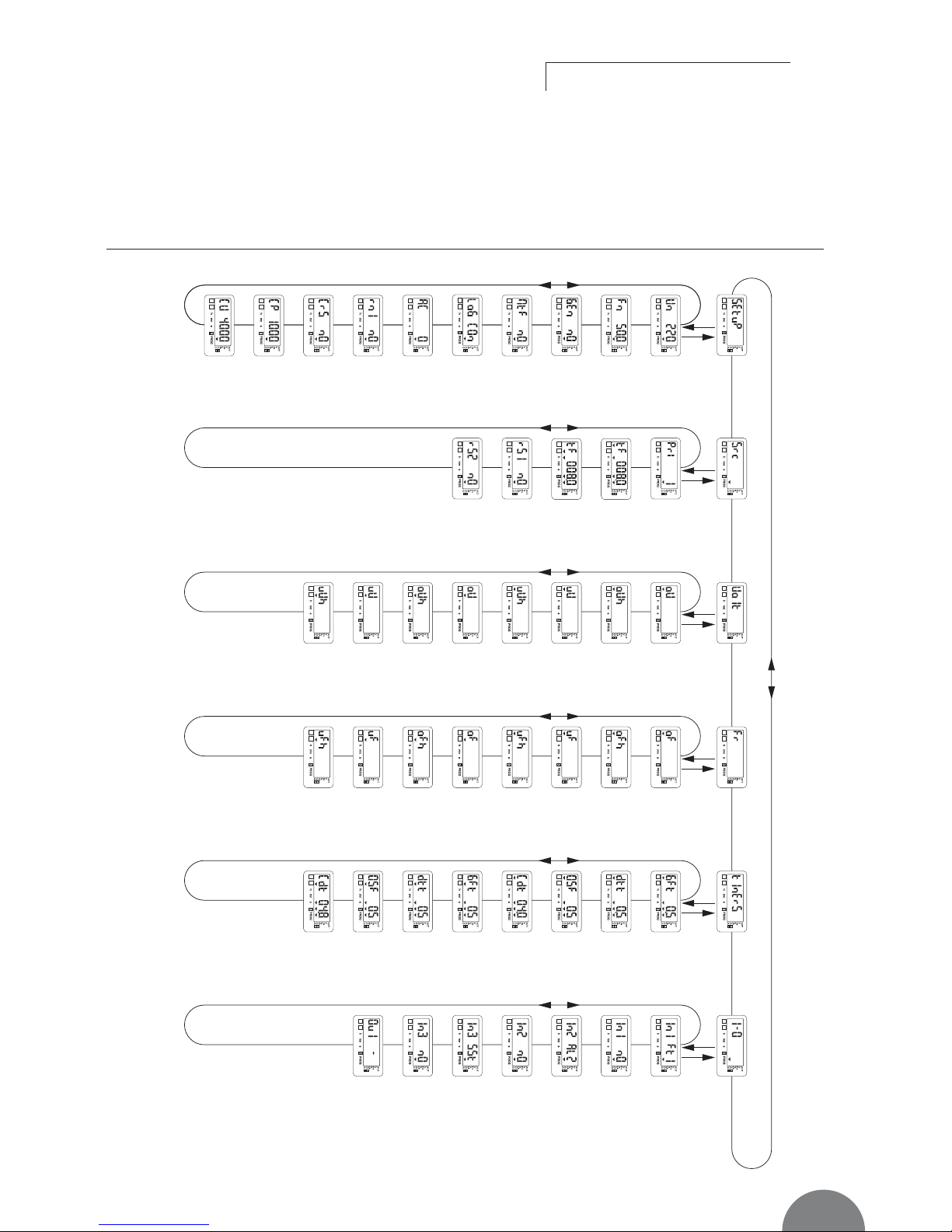
PROGRAMMING MENU ARCHITECTURE
1 2
1 2
1 2
1 2
1 2
1 2
1 2
1 2
1 2
1 2
1 2
1 2
1 2
1 2
1 2
1 2
1 2
1 2
1 2
1 2
1 2
1 2
1 2
1 2
1 2
1 2
1 2
1 2
1 2 1 2 1 2 1 2 1 2
1 2
1 2
1 2
1 2
1 2
1 2
1 2
1 2
1 2
1 2
1 2
1 2
1 2
1 2 1 2
1 2
1 2
1 2
1 2
Phase-Phase
nominal
voltage
ESC
See page 47 See page 48 See page 49 See page 50 See page 51 See page 52
Setup Source Voltage Frequency
Timer
2I/2O
ESCESCESC
ESC
ESC
Priority source
if no automatic
choice is
possible
Partial working
time for
source 1
Network 1
over voltage
threshold
Network 1
over voltage
threshold
hysteresis
Network 1
under voltage
threshold
hysteresis
Network 1
under voltage
threshold
Network 2
over voltage
threshold
Network 2
over voltage
threshold
hysteresis
Network 2
under voltage
threshold
hysteresis
Network 2
under voltage
threshold
Network 1
over frequency
threshold
Gen Failure
Timer source 1
Option 1
input 1
(variable
selection)
Option 1
input 1
(contact state
selection)
Option 2
input 2
(contact state
selection)
Option 2
input 2
(variable
selection)
Option 3
input 3
(contact state
selection)
Output
(variable
selection), if
Log ≠ ìimp ”
Option 3
input 3
(variable
selection)
Delay on
transfer timer
source 1
0 Secours
timer source
1
to source 2
Cool down
timer source 1
Gen Failure
Timer source 2
Delay to
transfer timer
source 2
0 Secours
timer source 2
to source 1
Cool down
timer source 2
Network 1
over frequency
threshold
hysteresis
Network 1
under
frequency
threshold
hysteresis
Network 1
under
frequency
threshold
Network 2
over frequency
threshold
Network 2
over frequency
thres
hold
hysteresis
Network 2
under
frequency
threshold
hysteresis
Network 2
under
frequency
threshold
Source 1
global working
time counter
reset
Source 2
global working
time counter
reset
Partial working
time for
source 2
Nominal
frequency
Genset start
signal state
retransfert
Manual
Impulse or
contactor
logic
Number of
auxiliary
contacts
Return to
position 0
Number of
permutation
counter Reset
Programming
partial code
modification
(global code
except rS1
and rS2)
Programming
code
modification
ATYS 470 B GB
Page 14

Programming
Controller
ATyS
OPERATION
ATyS C40
46
SOCOMEC - Réf. : 532 929 B
Presentation
Operational modes
Programming
Operation
Visualisation
Automatic sequences
PARAMETER MODIFICATION
>
Example:
Modify network nominal voltage from 400 to 230 V.
1
ATI 074 A
Press to access first digit (blinking)
Press
2X to display 2 (blinking)
Press
to access second digit (blinking)
Press
3X to display 3 (blinking)
Press to validate
Page 15

Programming
Controller ATyS
OPERATION
47
SOCOMEC - Réf. : 532 929 B
PARAMETERS CHARACTERISTICS
Network
nominal
frequency
Network nominal frequency 50 Hz or 60 Hz 50 Hz
1 2
>
Menu Setup
LCD Denomination Definition Setting Default
range values
1 2
Network
nominal voltage
Phase-Neutral voltage or Phase-Phase voltage From 100 V to
440 V
220 V
Manual
retransfer
“impulse” or
“contactor”
logic
Outputs control logic: impulse (IMP) or contactor (Con)
Activation of the feature YES or nO nO
Imp or con IMP
Restricted
access code
modification
Restricted access (counters rS1 and rS2) code modification
From 0000 to
9999
5000
Number of
auxiliary contact
Depends on changeover technology
(switch, contactor, breaker)
0 or 2 2
1 2
12
1 2
Genset start
signal state
Normally opened or closed. The same state for the 2
sources.
nO or nC nO
1 2
12
Return to 0
position
Allows to go to position 0 in case of network loss
(contactor logic type)
YES or nO nO
12
Number of
permutation
counter Reset
Automatic sequences counter reset YES or nO nO
1 2
Programming
code
Programming code modification From 0000 to
9999
1000
1 2
1 2
Page 16

Controller
ATyS
OPERATION
ATyS C40
48
SOCOMEC - Réf. : 532 929 B
Presentation
Operational modes
Programming
Operation
Visualisation
Automatic sequences
Programmation
>
Source Menu
LCD Denomination Definition Setting Default
range values
Priority source Priority source to start (1 or 2) if the internal logic could not
make any choice (rS1 = rS2 for exemple)
Partial working
time for source
1
Partial working
time for source
2
Reset of the
global working
time counter for
source 1
Partial workingtime counter for the source 1
Partial workingtime counter for the source 2
Reset of the global working time counter for source 1
1 or 2
from 000.1 to
999.9 hours
from 000.1 to
999.9 hours
nO or YES
1
008.0 hours
008.0 hours
nO
1 2
1 2
12
Reset of the
global working
time counter for
source 2
Reset of the global working time counter for source 2 nO or YES nO
12
1 2
1 2
Page 17

Programming
Controller ATyS
OPERATION
49
SOCOMEC - Réf. : 532 929 B
>
Volt Menu
Threshold detection starts from the loss of source
or source return sequence.
LCD Denomination / Definition Setting Default
range values
t100
Available source
Controlled value (voltage)
Over voltage threshold (oU)
Under voltage threshold (uU)
Over voltage hysteresys
threshold (oUh)
Under voltage hysteresys
threshold (uUh)
%
ATYS 243 A GB
Network 1 over voltage threshold From 102
to 120%
115%
Network 1 over voltage threshold hysteresis From 101
to 119% (< oU)
110%
Network 1 under voltage threshold From 80
to 98%
85%
Network 1 under voltage threshold hysteresis From 81
to 99% (> uO)
95%
Network 2 over voltage threshold From 102
to 120%
115%
Network 2 over voltage threshold hysteresis From 101
to 119% (< oU)
110%
Network 2 under voltage threshold From 80
to 98%
85%
Network 2 under voltage threshold hysteresis From 81
to 99% (> uU)
95%
1 2
1 2
1 2
1 2
1 2
1 2
1 2
1 2
1 2
Values definition: % of nominal values
Hysteresis values range is limited by thresholds values.
Page 18

Controller
ATyS
OPERATION
ATyS C40
50
SOCOMEC - Réf. : 532 929 B
Presentation
Operational modes
Programming
Operation
Visualisation
Automatic sequences
Programming
>
Frequency Menu
Threshold detection starts from the loss of source
or source return sequence.
LCD Denomination / Definition Setting Default
range values
t100
%
Available source
Controlled value (frequency)
Over frequency threshold (oU)
Under frequency threshold (uU)
Over frequency hysteresys
threshold (oUh)
Under frequency hysteresys
threshold (uUh)
ATYS 286 A GB
Network 1 over frequency threshold From 101
to 120%
105%
Network 1 over frequency threshold hysteresis From 100.5
to 119.5% (< oF)
103%
Network 1 under frequency threshold From 80
to 99%
95%
Network 1 under frequency threshold hysteresis From 80.5
to 99.5% (> uF)
97%
Network 2 over frequency threshold From 101
to 120%
105%
Network 2 over frequency threshold hysteresis From 100.5
to 119.5% (< oF)
103%
Network 2 under frequency threshold From 80
to 99%
95%
Network 2 under frequency threshold hysteresis From 80.5
to 99.5% (> uF)
97%
1 2
1 2
1 2
1 2
1 2
1 2
1 2
1 2
1 2
Values definition: % of nominal values
Hysteresis values range is limited by thresholds values.
Page 19

Programming
Controller ATyS
OPERATION
51
SOCOMEC - Réf. : 532 929 B
>
Menu Timer
LCD Denomination Definition Setting Default
range values
Gen Failure
Timer source 1
Delays source 1 failure detection
Delay to transfer
timer source 1
0 Secours Timer
source 1 to
source 2
Cool down
timer source 1
Standby network stability validation before transfer source 1 ->
source 2
Rest in zero position (open position) when transferring from
source 1 to source 2
Allows generator cooling down period after load’s retransfer
from source 1 -> source 2
From 0 to 60 s
From 0 to 60 s
From 0 to 20 s
From 0 to
30 mn
5 s
5 s
0 s
4 mn
1 2
1 2
1 2
Gen Failure
Timer source 2
Delays source 2 failure detection From 0 to 60 s 5 s
1 2
Delay to transfer
timer source 2
Standby network stability validation before transfer source 2 ->
source 1
From 0 to 60 s 5 s
1 2
0 Secours Timer
source 2 to
source 1
Rest in zero position (open position) when transferring from
source 2 to source 1
From 0 to 20 s 0 s
1 2
Cool down
timer source 2
Allows generator cooling down period after load’s retransfer
from source 2 -> source 1
From 0 to
30 mn
4 mn
1 2
1 2
12
Page 20

LCD Denomination/ Definition Setting range Default values
Input 1 SSt, Ft1, AL1, Ft2, AL2, /
MAn, MtF, /
Input 1 state nO or nC nO
Input 2 SSt, Ft1, AL1, Ft2, AL2, /
MAn, MtF, /
Input 2 state nO or nC nO
Input 3 SSt, Ft1, AL1, Ft2, AL2, /
MAn, MtF, /
Input 3 state nO or nC nO
Output* S1A, S2A, ScA, / /
* Non available in IMP logic (see LOG in SETUP menu).
Controller
ATyS
OPERATION
ATyS C40
52
SOCOMEC - Réf. : 532 929 B
Presentation
Operational modes
Programming
Operation
Visualisation
Automatic sequences
Programming
Output relays are NO type (construction) and
can not be configured as NC.
1 2
>
Inputs/Outputs Menu
Input state can be configured: NC or NO.
1 2
1 2
1 2
1 2
1 2
1 2
1 2
1 21 2
Page 21

Programming
Controller ATyS
OPERATION
53
SOCOMEC - Réf. : 532 929 B
>
Inputs/Outputs Menu
Inputs
1 2
Variable Description
SSt Start/stop transfer cycle.
Ft1 Fault input source 1. The fault led is blinking as soon as the input is active and Ft1 is displayed on LCD.
Reset when the input is de-actived (see diagram 2).
AL1 Alarm input source 1 (see diagram 1).
Ft2 Fault input source 2. The fault led is blinking as soon as the input is active and Ft2 is displayed on
LCD. reset when the input is de-actived (see diagram 2).
AL2 Alarm input source 2 (see diagram 1).
Man Information transfer system in manual mode. All automatic commands and test are inhibited as soon
as the input is activated.
MtF Remote manuel re-transfer. Feature identical to manual transfer on keypad. Re-transfer from priority
source to backup source is allowed from input activation (1s front). The Mtf variable in the setup menu
must be selected (Yes) to allow input recognition.
Variable Description
S1A Source 1 available.
Output activated as soon as source 1 is considered available (similar to front led source 1).
S2A Source 2 available.
Output activated as soon as source 2 is considered available (similar to front led source 2).
ScA Source 1 or Source 2 available.
Output activated as soon as source 1 or Source 2 considered available (similar to one of front led
source 1or Source 2).
* Non available in IMP logic (see LOG in SETUP menu).
Outputs*
Page 22

Controller
ATyS
OPERATION
ATyS C40
54
SOCOMEC - Réf. : 532 929 B
Presentation
Operational modes
Programming
Operation
Visualisation
Automatic sequences
>
AL1 Alarm diagram 1
Position G1
Position O
Position G2
sst
AL1
GFt 1
dtt 2
< tF 1
OSF 2 -> 1 OSF 1 -> 2 OSF 1 -> 2
tF 2 tF 1 < tF 2x
Cdt 2 dtt 2 Cdt 2
Cdt 1 dtt 1 Cdt 1
Start/stop order
Sensing
Start/stop order
Sensing
tG 1 = 0.5xtF1 + 1xtF1 + the old tG 1
tG 2 = 1xtF2 + x + 0.5xtF1 + the old tG 2
Input
dtt 1
ATYS 519 B GB
• An alarm is typically a warning information: fuel tank will
be empty very soon -> the genset will be stopped.
• During the functionning of one supply (G1 for example),
if an alarm AL1 appears, the second supply (G2 in that
case) is started at the end of GFt1 timer. G1 genset
is then stopped after Cdt1 timer. The emergency
genset G2 will then be maintained as long as the alarm
AL1 will be present. After AL1 disappearance, the basic
cycle will take over.
Programming
Page 23

Controller ATyS
OPERATION
55
SOCOMEC - Réf. : 532 929 B
>
Ft1 fault diagram 2
sst
Ft1
dtt 2
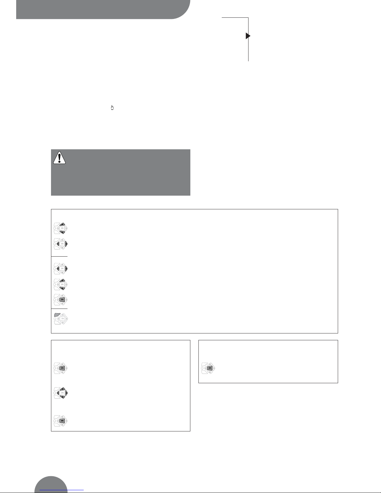
< tF 1
OSF 2 -> 1 OSF 1 -> 2 OSF 1 -> 2
tF 2 tF 1 < tF 2x
Cdt 2 dtt 2 Cdt 2
dtt 1 Cdt 1
Input
dtt 1
tG 1 = 0.5xtF1 + 1xtF1 + the old tG 1
tG 2 = 1xtF2 + x + 0.5xtF1 + the old tG 2
Position G1
Position O
Position G2
Start/stop order
Sensing
Start/stop order
Sensing
ATYS 520 B GB
• A fault can cause an important damage -> the genset
must be stopped immediately.
• During one supply operation (G1 for example), if Ft1
appears, the second supply (G2 in that case) is imme-
diately started. The initial G1 genset is then stopped
immediately after the transfer. The emergency genset
G2 will then be maintained as long as Ft1 will be
present. After Ft1 disappearance, the basic cycle will
take over.
Programming
Page 24

Operation
Controller
ATyS
OPERATION
ATyS C40
56
SOCOMEC - Réf. : 532 929 B
Presentation
Operational modes
Programming
Operation
Visualisation
Automatic sequences
PRESENTATION
Enter operation mode:
• Step 1: press and hold
the “TEST” push button for 5 s
• Step 2: enter the operation code (CE) using
navigation push buttons (code 4000)
• Step 3: press “validation”
push button
Exit operation mode:
Press and hold the “TEST” push button for 5 s
or automatic exit without action during around
2 min
Navigate in operation mode:
• Press “TEST” push button to access
different features
• Press “validation” push button to activate
required function
This mode allows in manual mode (not padlocked) to start
a test off load. In automatic mode, it allows to start a test,
on or off load.
Page 25
Controller ATyS
OPERATION
57
SOCOMEC - Réf. : 532 929 B
Operation
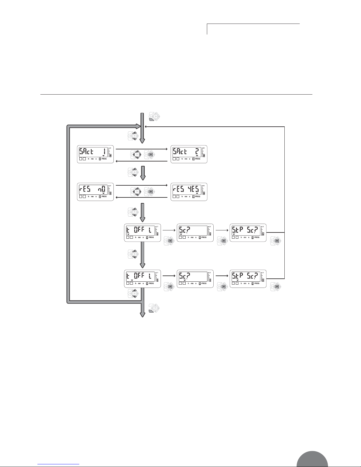
OPERATION MODE ARCHITECTURE
Exit: press 5 seconds
Yes, press
“validation”
Next source active :
source 2
Next source active :
source 1
Reset partial
counter : Yes
Test off Load source 1 Source 1 available ? Stop source 1 ?
Test off Load source 2 Source 2 available ? Stop source 2 ?
Reset partial
counter : No
No, press
“validation”
Yes, press
“validation”
Yes, press
“validation”
No, press
“validation”
Yes, press
“validation”
Enter: press 5 seconds and enter
the operation code (CE)
1 2
1 2
1 2 1 2
1 21 2
1 2
1 2
1 2
1 2
ATYS 523 A GB
Page 26

Controller
ATyS
OPERATION
ATyS C40
58
SOCOMEC - Réf. : 532 929 B
Presentation
Operational modes
Programming
Operation
Visualisation
Automatic sequences
Operation
ACTIVE SOURCES
>
Description
When a basic cycle is started, the first started group is the
one who has the least worked, or the one who is defined
in the menu “source” (in programming mode).
Nevertheless, in a punctual way it is possible to force
this choice of starting up of the next group by “operation” menu
>
Activation
- If the LCD indicate “SAct 1”, then the next “Source
Active”, or the next source which will be started, will be
the source 1.
- If the LCD indicate “SAct 2”, then the next “Source
Active”, or the next source which will be started, will be
the source 2.
RESET OF COUNTER
>
Description
During a basic cycle, each group works during a time
defined in the “source” menu in the programming mode.
This timer can be reset punctually during a running of
the associated genset.
>
Activation
- If the LCD indicate “rES nO”, then the timer is not
reseted.
- If the LCD indicate “rES YES”, then the timer is reseted.
Page 27

Controller ATyS
OPERATION
59
SOCOMEC - Réf. : 532 929 B
Operation
TEST OFF LOAD (ACCESSIBLE IN AUT / MODES)
>
Description
• This mode will start and stop remote by genset operation without load transfer
• The test is not possible during an automatic sequence
>
Keypad activation
After operation mode access, press mode push button
to make a test with the load led blinking and validate to
start the sequence.
Gen stopped
Validate
Yes
No
Gen?
Stop Gen?
Start Gen
1 2
1 2
1 2
1 2
1 2
ATYS 087 C GB
Page 28
Visualisation
Controller
ATyS
OPERATION
ATyS C40
60
SOCOMEC - Réf. : 532 929 B
Presentation
Operational modes
Programming
Operation
Visualisation
Automatic sequences
PRESENTATION
• This mode allows parameters to be displayed independently from mode /AUT (if programmed on
input) switch position
• No code required to access parameters visualisation
• Without any action during 10 seconds on the keypad,
the LCD displays voltage available on active network.
Navigation in visualisation mode:
• Press “up” and “bottom” push buttons to access required parameter
• Press “left” and “right” push buttons to navigate in the different menus
Page 29

Visualisation
Controller ATyS
OPERATION
61
SOCOMEC - Réf. : 532 929 B
VISUALISATION ARCHITECTURE MODE
1 2
1 2
1 2
1 2
1 2
1 2
1 2
1 2
1 2
1 2
1 2
1 2
1 2
1 2
1 2
1 2
1 2
1 2
W
*
orking time for the
next cycle or for the
current cycle
* Displays automatically comes back to this display if no action is performed on the product.
Sources Timers Counter Metering
Gen Failure Timer
source 1
Delay to transfer timer
source 2
Source 1 -> source 2
transfer counter
Delay to transfer timer
source 1
Cool down timer
source 2
Voltage
source 1
Frequency
source 1
Frequency
source 2
Voltage
source 2
Cool down timer
source 1
Gen Failure Timer
source 2
0 position stay
Timer from
source 1 to source 2
0 position stay
Timer from
source 2 to source 1
Global working time
for source 1
Global working time
for source 2
Partial working time
for source 1
Partial working time
for source 2
ATYS 524 A GB
Page 30

Controller
ATyS
OPERATION
ATyS C40
62
SOCOMEC - Réf. : 532 929 B
Presentation
Operational modes
Programming
Operation
Visualisation
Automatic sequences
Automatic sequences
OPERATION
>
Operation principle
C40 controler automatically starts and stops 2 gensets
if SSt input is activated (refer to programming).
Each genset has its own operational timer.
• tF1: partial operational timer (on one cycle, refer to
programming)
• tG1: global operational timer (from last counter reset).
>
Start sequence
From SSt start signal:
• If operational time on source 1 is greater than operational time on source 2,
-> Start source 1
• If operational time on source 2 is greater than operational time on source 1,
-> Start source 2
• If next source to start has been selected on HMI,
-> Start the required source.
Rq: In case of “non starting” of priority source, after
1 minute the second source is automatically started.
>
During the sequence
• If partial timer is counted down and sst stil active,
-> The second source is started and the load transferred
• If active source disappears before the end of the
sequence,
-> The second source is started and remains active
until the end of the partial timer (refer to diagrams 2
& 3)
>
Stop sequence
The cycle is stopped
• either when the state of the input (SSt) changes
• or when a fault appears
• or when the “manual” mode is activated.
• Diagram 1
Base cycle
dtt 2
tF 1
OSF 2 -> 1 OSF 1 -> 2 OSF 1 -> 2
tF 2 tF 1 < tF 2
Cdt 2 dtt 2 Cdt 2
Cdt 1 dtt 1 Cdt 1
tG 1 = 2xtF1 + the old tG 1
tG 2 = 1,5xtF2 + the old tG 2
SSt input
dtt 1
Position G1
Position O
Position G2
Start/stop order
Sensing
Start/stop order
Sensing
ATYS 525 B GB
tF1 1
• tG1 = fF1 + tF1 + tF1 + a
• number of cycle already realized by 1 = tG1/tF1 = 3, … cycles
tF1 1 tF1 1 a < tF1 1
Page 31

Controller ATyS
OPERATION
63
SOCOMEC - Réf. : 532 929 B
Automatic sequences
• Diagram 2:
source loss without reappearance before SSt state changeover
Complete genset loss
sst
GFt 1
dtt 2
< tF 1
OSF 1 -> 2
tF 2 x
Cdt 2
Cdt 1
tG 1 = 0.5xtF1 + the old tG 1
tG 2 = 1xtF2 + x + the old tG 2
Input
dtt 1
Position G1
Position O
Position G2
Start/stop order
Sensing
Start/stop order
Sensing
ATYS 526 B GB
• Diagram 3:
source loss and reappearance before SSt state changeover
Partial genset loss
sst
GFt 1
dtt 2
< tF 1
OSF 2 -> 1 OSF 1 ->2
tF 2 tF 1 x
Cdt 2
Cdt 1 dtt 1 Cdt 1
tG 1 = 0.5xtF1 0,5xFt1 + the old tG 1
tG 2 = 1xtF2 + x + 0.5xtF1 + the old tG 2
Input
dtt 1
Position G1
Position O
Position G2
Start/stop order
Sensing
Start/stop order
Sensing
ATYS 527 B GB
NB: in case of source 1 reappearance, it might be preferable not to retransfer immediately the load. Manual
retransfer feature can be activated if required from
keypad or remotely (cf. programming).
Page 32

Controller
ATyS
TROUBLESHOOTING GUIDE
ATyS C40
64
SOCOMEC - Réf. : 532 929 B
STATE ACT IO N
Electrical operation is not working • Verify voltage applied on terminals 9 Vdc to 30 Vdc for DC version
• Verify state of input MAN if selected
Product is faulty (fault is active) • Disconnect power supply and reconnect to reset fault
FT1, AL1, FT2, AL2 • In case of programming inputs FT1 or FT2, verify if external fault is not
active. If the external fault disappear it acquit the fault
• Verify inputs (NO, NC…) configuration
Source available led is never active • Press test lamp to verify led is operational (push 5 seconds)
when available • Verify nominal preset values (voltage and frequency)
• Verify voltage and frequency thresholds
The changeover switch does not transfer • Verify state of input MAN, if selected
after loss of main • Verify emergency source is available (ex: genset is started)
• Verify voltage applied on terminals
Test on load and off load
• Verify password to access test (5000)
can not be activated from keypad
• Verify state of input MAN, if selected
The changeover switch • Verify if dtt is counted down
does not re-transfer after main's return • Verify state of input MAN if selected
• Verify manual retransfer feature is not active
(press validation to allow retransfer)
Retransfer has been realised but • Verify if CDT is counted down
emergency source in still running (did not stop) • Verify Start Gen output relay command,
(contacts 13-14 or 53-54 depending on genset)
Electrical operation not according to commands • Verify control logic (impulse or contactor mode)
• Verify Rn variable in Setup menu
The product is in faulty position • Verify the number of AC in the setup menu. It must be in conformity with the
number of AC connected
• Verify the switch position
Error LCD Err XXXX • Send the product back to the manufacturer
 Loading...