

Page 1

CONTROLLER
ATyS C20/C30
Notice d’utilisation - Operating instructions
F
GB
MAKE YOUR BUSINESS SAFE
SOCOMEC GROUP SWITCHING PROTECTION & UPS
Page 2

F
Sommaire
LA GAMME ATyS _________________________________3
PRÉSENTATION GÉNÉRALE _______________________4
Présentation des produits ________________________4
INSTALLATION ___________________________________5
Montage _______________________________________5
Dimensions_____________________________________5
Caractéristiques_________________________________5
RACCORDEMENTS_______________________________6
Circuits de commande ___________________________6
Commande électrique __________________________11
FONCTIONNEMENT _____________________________12
Présentation___________________________________12
Modes d’utilisation _____________________________13
Programmation ________________________________14
Exploitation____________________________________24
Visualisation ___________________________________26
Séquences automatiques _______________________28
AIDE AU DÉPANNAGE ___________________________31
ANNEXES ______________________________________32
Typologie des réseaux __________________________32
Programmation et câblage ATyS__________________33
GB
THE ATyS RANGE _______________________________35
GENERAL PRESENTATION _______________________36
Product introduction ____________________________36
INSTALLATION __________________________________37
Summary
Mounting _____________________________________37
Dimensions ___________________________________37
Characteristics_________________________________37
CONNECTIONS _________________________________38
Control circuits_________________________________38
Electrical operation _____________________________43
OPERATION ____________________________________44
Presentation___________________________________44
Operational modes _____________________________45
Programming __________________________________46
Operation _____________________________________56
Visualisation ___________________________________58
Automatic sequences___________________________60
TROUBLESHOOTING GUIDE _____________________63
ANNEXES ______________________________________64
Network analysis _______________________________64
Programming and connections ATyS C30__________65
2
SOCOMEC - Réf.: 532 214 B
Page 3

35
SOCOMEC - Réf.: 532 214 C
The ATyS family proposes a complete motorised
changeover range including electrical and mechanical
interlocking. Manual operation is always possible on all
the products in case of emergency.
The electric command is realised via a motorised
module, electronically driven by 2 types of logic:
• Remote controlled: ATyS 3 products are controlled by
volt free contacts allowing the switch to be driven in 1,
0 or 2 position. These contacts can come from an
external control logic.
• Automatic control: AtyS 6 products integrate all
controls, timers and relays required to realise a
Normal/Emergency application.
ATyS 6e and 6m versions also integrate the remote
controlled feature.
The motorised and control modules can easily be
replaced without disconnecting the power cables.
Controller
ATyS
THE
ATyS
RANGE
>
This instruction manual applies to following
products:
• Controller ATyS C20/C30
>
Following products are delivered with their own
instruction manual:
• ATyS 3s
• ATyS 3e, 6s, 6e
• ATyS 6m
• Remote interfaces ATyS D10 & D20
• Centroller ATyS C40.
For personnel and product safety, please
read the contents of these operating
instructions carefully before connecting.
ATyS 3s ATyS 3e ATyS 6s ATyS 6e ATyS 6m ATyS C30 ATyS C20 ATyS C40
MOTORISED CHANGEOVER
Dual power supply
Metering
Remote interfaces ATyS D10 & D20
Changeover
controller
Dual gensetIntegrated control relay
Communication option
Com option
2 I/2 O option
2 inputs/2 outputs option
Page 4

ATYS 448 A
ATYS 453 A
Product introduction
Controller
ATyS
GENERAL PRESENTATION
ATyS C20/C30
36
SOCOMEC - Réf.: 532 214 C
Product introduction
LCD
Voltage sensing and
power supply terminals
Keypad
Control terminals Modular frame
ATYS C20
LCD
RJ45 terminal
Voltage sensing and
power supply terminals
Keypad
Control terminals Modular frame
ATYS C30
Page 5

Mounting
>
DIN rail mounting
Dimensions
Characteristics
37
SOCOMEC - Réf.: 532 214 C
Controller
ATyS
INSTALLATION
ATyS C20/C30
Mounting
Dimensions
Characteristics
>
IP
IP2 and class II on front face
>
Operation
• Temperature: -20 °C to +60 °C
• Humidity: 80% at 55 °C
95% at 40 °C
>
Consumption
7.5 VA max
>
Measurement category
Cat III
ATYS 449 A NBATYS 437 A
106
90
93
26,5
48
58
45
62
Page 6

Control circuits
400 Vac (P-P) APPLICATION WITH NEUTRAL CONDUCTOR
SWITCHING TYPE TECHNOLOGY
Controller
ATyS
CONNECTIONS
ATyS C20/C30
38
SOCOMEC - Réf.: 532 214 C
Control circuits
Electrical operation
Remote interfaces maximum connection
cable (RJ45) = 3 m.
Maximum control cables lenght = 10 m.
In case of longer distance, insert control
relays.
ATYS 426 A GB
* Only on DC versions.
• Configure the type of control logic in impulse mode
(see Programming chapter).
• Automatic Power supply 203-205 or 104-106
(see power supply chapter).
L1
L2
1
L3
N
Power
DPS
Double Power
Supply option
Ph
N
230 Vac
Control
III
GE
LOAD
L1
L2
L3
N
F2F1
F1, F2
Fuse protection
230 Vac 5 A
0C
CA1 CA0 CA2
I1 I2
O2
2
ONLY ON ATyS C30
ATyS D10 or D20
remote interface
Cable
RJ45 8/8
13 14 23 24 33 34 43 44 53 54
L1
106
103
L3N
104
L2
105
301 302 303 304305 306
L1
203
DC-*
DC+*
L3
205
Page 7

Controller ATyS
CONNECTIONS
39
SOCOMEC - Réf.: 532 214 C
Control circuits
400 Vac (P-P) APPLICATION WITH NEUTRAL CONDUCTOR
CONTACTOR TYPE TECHNOLOGY
ATYS 438 A GB
Remote interfaces maximum connection
cable (RJ45) = 3 m.
Maximum control cables lenght = 10 m.
In case of longer distance, insert control
relays.
* Only on DC versions.
• Configure the type of control logic in contactor (see
Programming chapter).
• Automatic Power supply 203-205 or 104-106
(see power supply chapter).
L1
L2
1
L3
N
K1 K2
K1
K2
III
GE
LOAD
L1
L2
O1 O2
L3
N
K2
K1
I1 I2
2
F2F1
F1, F2
Fuse protection
230 Vac 5 A
ONLY ON ATyS C30
Cable
RJ45 8/8
ATyS D10 or D20
remote interface
13 14 23 24 33 34 43 44 53 54
L1
106
103
L3N
104
L2
105
301 302 303 304305 306
L1
203
DC-*
DC+*
L3
205
Page 8

Controller
ATyS
CONNECTIONS
ATyS C20/C30
40
SOCOMEC - Réf.: 532 214 C
Control circuits
Electrical operation
Control circuits
400 Vac (P-P) APPLICATION WITH NEUTRAL CONDUCTOR
CIRCUIT BREAKER TYPE TECHNOLOGY
>
Electrical interlocking via external control relays
ATYS 439 A GB
Remote interfaces maximum connection
cable (RJ45) = 3 m.
Maximum control cables lenght = 10 m.
In case of longer distance, insert control
relays.
* Only on DC versions.
• Configure the type of control logic in contactor (see
Programming chapter).
• Automatic Power supply 203-205 or 104-106
(see power supply chapter).
LOAD
L1
L2
1
L3
N
K2
POS 1
closing
K1
POS 2
opening
POS 2
closing
K2
K1
III
POS 1
opening
O1 O2
AUXILIARY CONTACT
BRE. 1 BRE. 2
I1 I2
L1
L2
L3
N
2
F2F1
F1, F2
Fuse protection
230 Vac 5 A
GE
13 14 23 24 33 34 43 44 53 54
301 302 303 304305 306
DC-*
DC+*
ONLY ON ATyS C30
ATyS D10 or D20
remote interface
Cable
RJ45 8/8
103
L3N
104
L2
105
L1
106
L1
203
L3
205
Page 9

Controller ATyS
CONNECTIONS
41
SOCOMEC - Réf.: 532 214 C
Control circuits
400 Vac (P-P) APPLICATION WITH NEUTRAL CONDUCTOR
CIRCUIT BREAKER TYPE TECHNOLOGY
>
Electrical interlocking not integrated
This drawing is not including the electrical
interlock.
ATYS 440 B GB
Remote interfaces maximum connection
cable (RJ45) = 3 m.
Maximum control cables lenght = 10 m.
In case of longer distance, insert control
relays.
It might be necessary for some breakers not
to set up OMR and OMF timers to 0.
(refer to programming)
* Only on DC versions.
• Configure the type of control logic in breaker
(see Programming chapter)
• Automatic Power supply 203-205 or 104-106
(see power supply chapter).
LOAD
L1
L2
1
L3
N
OPENING
CLOSING
Breaker 1
Breaker 1
Breaker 2
Breaker 2
I1 I2
L1
L2
L3
N
2
F2F1
F1, F2
Fuse protection
230 Vac 5 A
GE
13 14 23 24 33 34 43 44 53 54
301 302 303 304305 306
DC-*
DC+*
ONLY ON ATyS C30
Cable
RJ45 8/8
ATyS D10 or D20
remote interface
103
L3N
104
105
L2
L1
106
L1
203
L3
205
Page 10

Controller
ATyS
CONNECTIONS
ATyS C20/C30
Control circuits
42
SOCOMEC - Réf.: 532 214 C
Control circuits
Electrical operation
Denomination
Terminals
Description Characteristics
Recommended
section
Power supply N (103) Neutral 440 V ac (phase-phase) 1.5 mm
2
Source L3 (104) Phase 3 maximum, 50/60 Hz
L2 (105) Phase 2 254 V ac (phase neutre)
L1 (106) Phase 1 maximum, 50/60 Hz
Power supply L1 (203) Phase 1 440 V ac (phase-phase) 1.5 mm
2
Source L3 (205) Phase 3 maximum
Power supply DC
(1)
DC- Power supply 0 V From 9 V dc to 30 V dc 1.5 mm
2
12Vdc, 24Vdc
DC+ Power supply +V dc
Genset
(2)
13 Genset start/stop relay - 2 stable positions Dry contact 1.5 mm
2
start signal 14 Programmable state - factory setting = NO, close to start 5A AC1/250 V
Control 23 Impulse mode: order to close source 5 A AC1/250 V 1.5 mm
2
(impulse, 24 Contactor mode: order to close contactor source
contactor Breaker mode: order to close breaker source
and breaker 33 Impulse mode: order to close source 5 A AC1 / 250 V 1.5 mm
2
mode to 34 Contactor mode: order to close contactor source
programm) Breaker mode: order to close breaker source
43 Impulse mode: order to reach position 0 5 A AC1/250 V 1.5 mm
2
44 Contactor mode: programmable relay O1
Breaker mode: order to open breaker source
53 Impulse mode: programmable relay O2 5 A AC1/250 V 1.5 mm
2
54 Contactor mode: programmable relay O2
Breaker mode: order to open breaker source
Information 301 Auxiliary contact information position 1 AC1 Do not connect to 1.5 mm
2
auxiliary 302 Auxiliary contact information position 0 AC0 any power supply
contacts 303 Auxiliary contact information position 2 AC2
Programmable 304 Programmable input In1 Do not connect to 1.5 mm
2
Inputs 305 Programmable input In2 any power supply
Common 306 Specific voltage supply Do not connect to 1.5 mm
2
input Common terminals 301 to 306 any power supply
Remote interface
RJ Remote interface ATyS D10 or D20 Maximum connection RJ45 8/8
connection cable 3 m
(1) Only on DC version
(2) Refer to programming, Setup, to modify relay state.
2
1
2
2
2
1
1
1
2
1
Page 11

Electrical operation
POWER SUPPLY
ATyS C20/C30 integrates 2 power inputs (104-106, 203-
205), and consider the available source to keep the
product operational. Product supplied when voltage on
terminals ≥ 100 Vac
For the DC version, these is only one power supply input
(DC-, DC+).
Controller ATyS
CONNECTIONS
43
SOCOMEC - Réf.: 532 214 C
ATYS 444 A GB
: terminals 104-106 : terminals 203-205
21
AUT position
priority power source
backup power source
product ON
1
2
Page 12

Presentation
The product allows:
• sources control,
• automatic transfer control in AUT mode,
• parameters configuration,
• voltage and frequency metering,
• system state display,
• alarm or fault indication,
Controller
ATyS
OPERATION
ATyS C20/C30
44
SOCOMEC - Réf.: 532 214 C
Presentation
Operational modes
Programming
Operation
Visualisation
Automatic sequences
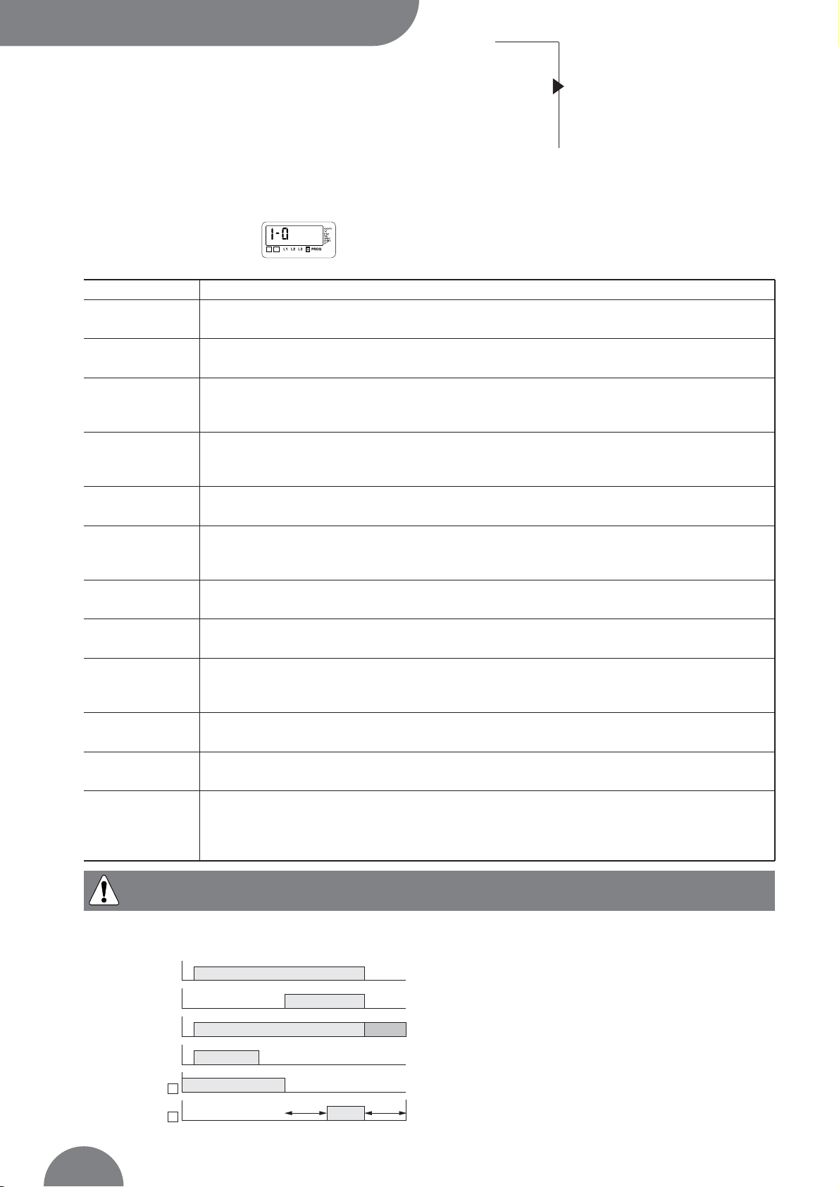
SOFTWARE VERSION
Displayed after reset.
(3 minutes power off action to allow reset).
Version
number
ATYS 428 A GB
ATYS 427 A GB
* only on ATyS C30.
FAULT led
Led is on when product is faulty.
Disconnect power supplies to reset
POWER led
Green led is on when product is
powered
RJ45 connection*
RJ45 terminal for
ATyS D10 or D20.
If connected, the
LCD is off
Sources state
- Led is on: source = OK
- Led is off: source is not available
LCD
7 digits + 14 pointers
Keypad
Escape Navigation
LCD & leds test
Switch state
2 green leds:
- switch I state
- switch II state
Operations
Operational modes
- Automatic sequence simulator (test on load)
- Genset remote start (test off load)
- Changeover switch position control (local or remote)
Validation
Page 13

Controller ATyS
OPERATION
45
SOCOMEC - Réf.: 532 214 C
PHASES ROTATION CONTROL
Operational modes
VISUALISATION
Measured values & parametered timers display. Always
accessible without code.
PROGRAMMING
Parameters configuration. Password access (code 1000
from factory).
The manual mode must be programmed on an input if
required.
OPERATION
Test sequences. Password access (code 4000).
Available functions in mode
Available functions in “AUT ” mode
Programming Visualisation
Programming Visualisation
Loss of main
source
sequence
Main’s
return
sequence
Operation
Test off load Test on load
Operation
Test off load
Programming
Code
Operation
Code
Programming
Code
Operation
Code
Function available only on source in case of 3NBL,
4NBL and 41NBL network.
If a fault is detected, the source is not indicated as
available.
1
1
ATYS 219 A
ATYS 441 A
displayed according to faulty source.
1 2
V1
NOK
V3V2
V1
OK
V2V3
Page 14

Programming
Controller
ATyS
OPERATION
ATyS C20/C30
46
SOCOMEC - Réf.: 532 214 C
Presentation
Operational modes
Programming
Operation
Visualisation
Automatic sequences
• This mode allows product parameters configuration
• Always accessible in mode (when programmed on
an input)
• Always accessible in AUT mode, changeover switch on
priority source, priority source being available
• Not accessible when “test off load”, “test on load”
functions are active or during automatic sequence.
Parameters requiring programming before
use:
• type of network
• nominal voltage
• nominal frequency
• control logic
• number of auxiliary contact.
>
Navigation in the menus
• Parameters access: Press “up”, “down”, “left” & “right” push buttons
• Parametermodification: press “left” & “right” push button to access the parameter to modify
Press “up’’ and “down” push buttons to modify the parameter
and “validate”
• Return to main menu: press “ESC” push button
Value is only modified after validation
+
or
+
>
Programming exit
• Press and hold for 5 s
“validation” push button
>
Programming access
• Step 1: press and hold for 5 s
“validation” push button
• Step 2: enter code (factory code = 1000)
using navigation push buttons
• Step 3: press validation
push button
Page 15

Programming
Controller ATyS
OPERATION
47
SOCOMEC - Réf.: 532 214 C
PROGRAMMING MENU ARCHITECTURE
ESC ESC ESC ESC
Setup Voltage
Frequency
Timer 2I/ 2O
Type of network
1 2
Network 1 over
voltage
threshold
1 2
Network 1 over
frequency
threshold
1 2
Main Failure
Timer
Phase-Phase
nominal voltage
Nominal
frequency
1 2
Network 1 over
voltage
threshold
hysteresis
1 2
Network 1 over
frequency
threshold
hysteresis
1 2
Delay on
Transfer
Timer
Network 1
under voltage
threshold
1 2
Network 1
under frequency
threshold
1 2
O main failure
Timer
Network priority
selection:
or
21
Genset start
signal state
Manuel
retransfer
1 2
Network 1
under voltage
threshold
hysteresis
1 2
Network 1
under frequency
threshold
hysteresis
1 2
Main Return
Timer
1 2
Option 1
Input 1 (variable
selection)
1 2
Option 1
Input 1 (contact
state selection)
1 2
Option 2
Input 2 (variable
selection)
1 2
Option 2
Input 2 (contact
state selection)
1 2
Output 1*
1 2
Output 2*
1 2
Load shedding
timer**
Impulse,
breaker or
contactor logic
Number of
auxiliary contact
Return on
position 0
->
2
1
Return on
position 0
->
1
2
1 2
Network 2 over
voltage
threshold
1 2
Network 2 over
frequency
threshold
1 2
O main Return
Timer
Number of
permutation
counter Reset
1 2
Network 2 over
voltage
threshold
hysteresis
1 2
Network 2 over
frequency
threshold
hysteresis
1 2
Cool Down
Timer
1 2
Network 2
under voltage
threshold
1 2
Network 2
under frequency
threshold
Programming
code modification
See page 50 See page 51 See page 52 See pages 53 to 55See page 49
1 2
Network 2
under voltage
threshold
hysteresis
1 2
Network 2
under frequency
threshold
hysteresis
* Availability of output functions depending on control logic selection (impulse, breaker or contactor logic)
** Displayed if LS variable has been selected.
ESC
1 2
1 2
12
12
12
1 2
1 2
1 2
1 2
1 2
1 2
1 2
1 2
1 2 1 2 1 2 1 2
1 2
Page 16

Programming
Controller
ATyS
OPERATION
ATyS C20/C30
48
SOCOMEC - Réf.: 532 214 C
Presentation
Operational modes
Programming
Operation
Visualisation
Automatic sequences
PARAMETER MODIFICATION
>
Example:
Modify network nominal voltage from 400 to 230 V.
1
ATI 074 A
Press to access first digit (blinking)
Press
2X to display 2 (blinking)
Press
to access second digit (blinking)
Press
3X to display 3 (blinking)
Press to validate
Page 17

Programming
Controller ATyS
OPERATION
49
SOCOMEC - Réf.: 532 214 C
Network
nominal
frequency
Network nominal frequency 50 Hz or 60 Hz 50 Hz
1 2
PARAMETERS CHARACTERISTICS
>
Menu Setup
LCD Denomination Definition Setting Default
range values
* Refer to annexes.
(1) It might be necessary for some breakers not to set up OMR and OMF timers to 0. (2 sec.)
1 2
Type of
network*
Number of active conductors of controlled network
(refer to annexes)
1BL, 2BL,
2NBL, 3NBL,
4NBL, 41 NBL
4NBL
Network
nominal voltage
Phase-Neutral voltage for 1BL & 41NBL
Phase-Phase voltage for others
from 100 V
to 400 V
400 V
Network priority
selection
Manual
Retransfer
Activation of the feature
Keypad selection (1 or 2)
Also possible via external contact using option
1 or 2
(
or )
2
1
1 ()
1
Programming
code
modification
Possible to change the programming code from 0000 to
9999
Yes or No
1000
No
Number of
permutation
counter Reset
Allows source -> source automatic sequences
counter reset
21
Yes or No No
Type of control
logic selection
Impulse, contactor or breaker.
It might be necessary for some breakers not to set up
OMR and OMF timers to 0 (2 sec. for exemple).
Imp, con, brE Imp
1 2
1 2
1 2
1 2
1 2
Genset start
signal state
Normally opened or closed NO or NC NO
1 2
1 2
Number of
auxiliary contact
Depending on the number if available auxiliary contacts
(switch, contactor, breaker)
0, 2, 3 2
Parameter 1,
return in
position 0
Allows to go to position 0 in case of voltage or frequency
outage (out if the defined U, f range)
Yes or No No
Parameter 2
return in
position 0
Allows to go to position 0 in case of voltage or frequency
outage (out if the defined U, f range)
Yes or No No
1 2
12
12
12
Page 18

Programming
Controller
ATyS
OPERATION
ATyS C20/C30
50
SOCOMEC - Réf.: 532 214 C
Presentation
Operational modes
Programming
Operation
Visualisation
Automatic sequences
>
Volt Menu
Threshold detection starts from the loss of source
or source return sequence.
LCD Denomination/ Definition Setting Default
range values
ATYS 243 A GB
Network 1 over voltage threshold From 102
to 120%
115%
Network 1 over voltage threshold hysteresis From 101
to 119% (< oU)
110%
Network 1 under voltage threshold From 80
to 98%
85%
Network 1 under voltage threshold hysteresis From 81
to 99% (> uO)
95%
Network 2 over voltage threshold From 102
to 120%
115%
Network 2 over voltage threshold hysteresis From 101
to 119% (< oU)
110%
Network 2 under voltage threshold From 80
to 98%
85%
Network 2 under voltage threshold hysteresis From 81
to 99% (> uU)
95%
1 2
1 2
1 2
1 2
1 2
1 2
1 2
1 2
1 2
Values definition: % of nominal values
Hysteresis values range is limited by thresholds values.
%
Controlled value (voltage)
Over voltage threshold (oU)
Over voltage hysteresys
threshold (oUh)
Available source
t100
Under voltage hysteresys
threshold (uUh)
Under voltage threshold (uU)
Page 19

Programming
Controller ATyS
OPERATION
51
SOCOMEC - Réf.: 532 214 C
>
Frequency Menu
Threshold detection starts from the loss of source
or source return sequence.
LCD Denomination/ Definition Setting Default
range values
t100
%
Available source
Controlled value (frequency)
Over frequency threshold (oU)
Under frequency threshold (uU)
Over frequency hysteresys
threshold (oUh)
Under frequency hysteresys
threshold (uUh)
ATYS 286 A GB
Network 1 over frequency threshold From 101
to 120%
105%
Network 1 over frequency threshold hysteresis From 100.5
to 119.5% (< oF)
103%
Network 1 under frequency threshold From 80
to 99%
95%
Network 1 under frequency threshold hysteresis From 80.5
to 99.5% (> uF)
97%
Network 2 over frequency threshold From 101
to 120%
105%
Network 2 over frequency threshold hysteresis From 100.5
to 119.5% (< oF)
103%
Network 2 under frequency threshold From 80
to 99%
95%
Network 2 under frequency threshold hysteresis From 80.5
to 99.5% (> uF)
97%
1 2
1 2
1 2
1 2
1 2
1 2
1 2
1 2
1 2
Values definition: % of nominal values
Hysteresis values range is limited by thresholds values.
Page 20

Programming
Controller
ATyS
OPERATION
ATyS C20/C30
52
SOCOMEC - Réf.: 532 214 C
Presentation
Operational modes
Programming
Operation
Visualisation
Automatic sequences
>
Menu Timer
1 2
LCD Denomination Definition Setting Default
range values
Main Failure
Timer
Delays priority network failure detection
Delay on
transfer Timer
O Main failure
Timer
Main return
Timer
Standby network stability validation before transfer
Rest in O position when transferring
from main network to secondary network
Main network stability validation before re-transfer
from 0 to 60 s
from 0 to 60 s
from 0 to 20 s
from 0 to 30 min
5 s
5 s
0 s
2 min
1 2
1 2
1 2
O main return
Timer
Rest in O position when re-transferring from standby
network to main network
from 0 to 20 s 0 s
1 2
Cool down
Timer
Allows generator cooling down period after load’s
retransfer from standby source (generator) to Main source
from 0 to 30 min 4 min
1 2
1 2
Page 21

Programming
Controller ATyS
OPERATION
53
SOCOMEC - Réf.: 532 214 C
LCD Denomination/ Definition Setting range Default values
Input 1 Ft1, Ft2, Ft3, Ft4, Pri, Mtf,/ /
S2A, MAN, CtS, tol, tfl, EJP
Input 1state NO, NC, / NO
Input 2 Ft1, Ft2, Ft3, Ft4, Pri, Mtf,/ /
S2A, MAN, CtS, tol, tfl, EJP
Input 2 state NO, NC, / NO
Output 1 S1A, S2A, LS, / /
Output 2 S1A, S2A, LS, / /
Input state can be configured: NC or NO.
1 2
1 2
1 2
1 2
1 2
1 2
Output relays are NO type (construction) and
can not be configured as NC.
1 2
>
Inputs/Outputs Menu
Page 22
Programming
Controller
ATyS
OPERATION
ATyS C20/C30
54
SOCOMEC - Réf.: 532 214 C
Presentation
Operational modes
Programming
Operation
Visualisation
Automatic sequences
>
Inputs/Outputs Menu
Inputs
(1) This information is the only considered in case of option configuration. Programming variable Pri
is then inhibited.
1 2
• EJP cycle
ATYS 442 B GB
Variable Description
Ft1 Fault input 1. The fault led is blinking as soon as the input is active and
Ft1 is displayed on LCD. Reset when the input is de-activated
Ft2 Fault input 2. The fault led is blinking as soon as the input is active and Ft2 is displayed on LCD.
Reset when the input is de-activated
Ft3 Fault input 3. The fault led is blinking as soon as the input is active and Ft3 is displayed on LCD.
The transfer switch is immediately driven in 0 position (only in contactor mode).
Keypad action (Validation) necessary to Reset the fault
Ft4 Fault input 4. The fault led is blinking as soon as the input is active and Ft4 is displayed on LCD.
The transfer switch is immediately driven in 0 position (only in contactor mode).
Keypad action (Validation) necessary to Reset the fault
Pri
(1)
Priority network selection.
Network 1 has priority when input is not activated. Network 2 has priority if input is active
Mtf Remote manuel re-transfer. Feature identical to manual retransfer on keypad.
Re-transfer from priority network to backup network is allowed from input activation (1 s front).
The Mtf variable in the setup menu must be selected (Yes) to allow input recognition
S2A Information source 2 available (Genset) used instead of voltage/frequency measurement
(inhibited when S2A is selected)
Man Information transfer system in manual mode
All automatic commands (+ test on load) are inhibited as soon as the input is activated
CtS Remote transfer control. Possible to initiate transfer from priority source to backup source
before DTT ends. If DTT is set to its maximum value (60s), the transfer is initiated as soon as
the input is activated (1 s front)
tol Remote test on load. Started from input activation.
Re-transfer is blocked until input de-activation
tfl Remote test off load
Started from input activation (remote genset start/stop)
EJP 2 inputs are automatically affected to EJP
• input 1 for EJP advice, to start generator
• input 2 to transfer on emergency source
Retransfer is activated when input 2 dissapears
EJP advice (input 1)
EJP transfer (input 2)
Start generator
DTT
Source 1
Source 2
OMF OMR
CDT
Page 23

Variable Description
S1A Source 1 available.
Output activated as soon as source 1 is considered available (similar to front led source 1)
S2A Source 2 available.
Output activated as soon as source 2 is considered available (similar to front led source 2)
LS Load shedding relay. LS timer corresponds to time available to disconnect the shed loads.
The relay is activated before permutation on standby network according to LS timer.
The relay is de-activated after retransfer on mains network and LS timer countdown
Programming
Controller ATyS
OPERATION
55
SOCOMEC - Réf.: 532 214 C
>
Inputs/Outputs Menu
Outputs
DTT timer
LS timer
Priority source -
emergency source
transfer
LS relay Activation
Emergency source -
priority source
transfer
LS timer
Output Function Default Value Setting range
For LS: For LS:
S1A, S2A, LS, / 0 to 60 s (≤ DTT)* 3 s
1 2
1 2
In case of LS function selection, it is required to configure associated LS timer.
• Example: LS configuration (output relay Ou1, 3 seconds):
• Load shedding cycle
1 2
1 2
The output is de-activated in case of loss of
power. It may then be required to put in
parrallel with the load shedding ouptut relay,
position 2 auxiliary contact. This would avoid taking
back the load in case of loss of emergency source in
emergency position.
Position II (emergency) AC activation
1 2
LS AC II Load shedding output
ATYS 269 A
The load shedding can’t be used with the priority
network (priority source = source ). In this case, LS
output is not valid.
2
ATYS 334 A GB
* In case of DTT variable configuration below LS, LS will be automatically set to DTT value.
Page 24

Operation
Controller
ATyS
OPERATION
ATyS C20/C30
56
SOCOMEC - Réf.: 532 214 C
Presentation
Operational modes
Programming
Operation
Visualisation
Automatic sequences
PRESENTATION
Enter operation mode:
• Step 1: press and hold
the “TEST” push button for 5 s
• Step 2: enter the operation code (CE) using
navigation push buttons (code 4000)
• Step 3: press “validation”
push button
Exit operation mode:
Press and hold the “TEST” push button for 5 s
or automatic exit without action during around
2 min
Navigate in operation mode:
• Press “TEST” push button to access
different features
• Press “validation” push button to activate
required function
OPERATION MODE ARCHITECTURE
ATYS 432 A GB
This mode allows in manual mode (not padlocked) to start
a test off load. In automatic mode, it allows to start a test,
on or off load.
Enter: press 5 seconds
Led “test on load”
is blinking
Led “test off load”
is blinking
Yes, press
No, press
“TEST”
No, press
“TEST”
“validation”
Yes, press
“validation”
Exit: press 5 seconds
12
12
Led “TEST ON LOAD”
is fixed
Led “TEST OFF LOAD”
is fixed
TEST ON LOAD
Loss of priority
source sequence
TEST OFF LOAD
Genset start
sequence
Page 25

Operation
Controller ATyS
OPERATION
57
SOCOMEC - Réf.: 532 214 C
TEST OFF LOAD (ACCESSIBLE IN AUT/ MODES)
It can be activated from:
• operation mode
• ATyS D20 interface
• programming input (TFL) if selected.
This test is made for applications where emergency
source is typically a genset (priority source must be
source ). This test can be activated, in automatic
mode, changeover switch in position , source
available.
>
Description
• This mode will start and stop remotely genset operation
without load transfer
• The test is not possible during an automatic sequence
>
Keypad activation
After operation mode access, press mode push button
to make the test off load led blinking and validate to
start the sequence.
11
1
2
TEST ON LOAD (ACCESSIBLE IN AUT MODE)
It is activated from:
• operation mode
• ATyS D20 interface
• programming input (TOL) if selected.
ATI 087 B GB
>
Description:
• This test simulates a loss of priority source situation.
The sequence generates load transfer from priority
source to emergency source after backup source start
up operation (in case of genset). The return sequence
always keeps manual re transfer feature activated (from
priority source availability). All timers are counted down.
>
Keypad activation
After operation mode access, press mode push button
to make test on load led blinking and validate to start a
cycle.
The test is only possible in automatic mode, the changeover switch in priority source position, priority source
being available.
>
Keypad or remote operation
>
Remote activation via specific input
It is also possible to start a test on load remotely with
the programming input TOL if selected.
The cycle is started from contacts closure.
The re-transfer is initiated from contacts opening.
Automatic cycle keeps priority.
1 2
1 2
Start gen relay is closed if source has
priority.
2
The re-transfer from emergency source to
priority source is blocked and only authorized
after manuel retransfer validation (keypad
activation) or terminals opening.
Manual retransfer to validate on keypad.
In retransfer sequence from emergency
source to priority source, the MRT count
down is set to 10 seconds (maximum),
unless a lower value has been programmed.
1 2
start Gen
Gen ?
1 2
Yes
Stop Gen ?
1 2
No
Validate
1 2
Gen stopped
Page 26

Visualisation
Controller
ATyS
OPERATION
ATyS C20/C30
58
SOCOMEC - Réf.: 532 214 C
Presentation
Operational modes
Programming
Operation
Visualisation
Automatic sequences
PRESENTATION
• This mode allows parameters to be displayed
independently from mode / AUT switch position
(if programmed on input)
• No code required to access parameters visualisation
• Without any action during 5 seconds on the keypad,
the LCD displays voltage available on active network.
In case of changeover switch on 0 position, priority
network voltage is displayed.
Navigation in visualisationmode:
• Press “up” and “bottom” push buttons to access required parameter
• Press “left” and “right” push buttons to navigate in the different menus
Page 27

Visualisation
Controller ATyS
OPERATION
59
SOCOMEC - Réf.: 532 214 C
MENUS
Metering Timers Counter
Phase-neutral voltage V1 Main Failure Timer Priority source ->
network Emergency source
transfer counter
Phase-neutral voltage V2 Delay on Transfer Timer
network
Phase-neutral voltage V3 O Main Failure Timer
network
Network frequency Main Return Timer
Phase-phase U12 O Main Return Timer
network
Phase-phase U23 Cool Down Timer
network
Phase-phase U31 Load shedding*
network
Phase-neutral voltage V1
network
Phase-phase U31
network
Network frequency
* If selected.
2
2
2
1
1
1
1
1
1
1
VISUALISATION ARCHITECTURE MODE
All values indicated might not be available according to programmed network. Refer to annexes.
1 2
1 2
1 2
1 2
1 2
1 2
1 2
1 2
1 2
1 2
1 2
1 2
1 2
1 2
1 2
1 2
1 2
Page 28

Automatic sequences
Controller
ATyS
OPERATION
ATyS C20/C30
60
SOCOMEC - Réf.: 532 214 C
Presentation
Operational modes
Programming
Operation
Visualisation
Automatic sequences
MANUAL MODE/ AUTOMATIC MODE
>
Manual mode - Automatic mode
permutation/power supply reappearance
• As soon as man input desapears (if selected), the
automatic mode is active
• Voltages and frequencies are verified to define new stable
position of the changeover switch
• The same table can be taken into account after
complete power supply loss (the product must be
completely discharged to reset = 3 minutes.)
>
New stable position of the changeover switch
Refer to timer menus for MFT, MRT or DTT timers
definition.
Changeover switch Sources availability New position
initial position
Priority source Priority source available, Priority source
emergency source available or unavailable
Priority source Priority source unavailable for MFT time period, Emergency source. If emergency source
emergency source available or unavailable unavailable start emergency source first and wait
for DTT timer period before transfer
Emergency source Emergency source available, Emergency source
priority source unavailable
Emergency source Emergency source available, Priority source
priority source available for MRT time period
Emergency source Emergency source not available, Priority source
priority source available
Position 0 Priority source available, Available source to count down MRT before
emergency source unavailable transfer to priority source
Position 0 Priority source available, Priority source
emergency source unavailable
Position 0 Priority source unavailable, Emergency source
emergency source available
Position 0 Priority source unavailable, No action (because no supply).
emergency source unavailable When supply becomes available change to priority
source or emergency source
The switch transfers to new stable position as soon as Automatic mode is active.
LOSS OF PRIORITY SOURCE AUTOMATIC SEQUENCE
This sequence is started as soon as the switch is in
automatic mode and in priority position (position I source ).
• source is available
• transfer switch is in position I
• source is available or unavailable
>
Available source
Source being within programmed voltage and frequency
settings, phases rotation being correct.
>
Specific feature: remote transfer control
It is possible to transfer from main source to emergency
source before DTT finishes up and to allow transfer with
CTS option if selected on an unput. DTT is automatically
set up to its maximum value as soon as CTS is selected.
2
1
1
Page 29

Automatic sequences
Controller ATyS
OPERATION
61
SOCOMEC - Réf.: 532 214 C
>
Sequence description
Example:
position I = priority source ( )
position II = emergency source type Genset ( )
2
1
ATYS 443 A GB
Loss of
mains?
Automatic mode
Loss of main?
Yes
No
Count down MFT
Reset MFT
Stop gen
MFT = 0
Main comes back
before MFT ends?
Yes
Reset DTT
No
Priority
source?
Gen fails
Emergency
Yes
Start Genset
source
available?
No
Count down
DTT = 0
OMF 0 ?
Genset
start up
Yes
No
No
No
CTS = 1 ?
Yes
Transfer I > 0
Count down OMF
OMF = 0
Transfer 0 > II Transfer I > II
Transfer I > I I
Go to priority source
return automatic
sequence
Page 30

Automatic sequences
Controller
ATyS
OPERATION
ATyS C20/C30
62
SOCOMEC - Réf.: 532 214 C
Presentation
Operational modes
Programming
Operation
Visualisation
Automatic sequences
RETURN TO PRIORITY SOURCE
This sequence is activated as soon as the changeover
switch is in automatic mode and in emergency position
(position II):
• the priority source is not available
• the changeover switch is in emergency position (ex:
genset)
• the emergency source is available.
2
1
>
Specific feature: manual re-transfer
• When priority source comes back, it can be required
not to automatically retransfer and wait for a more
adequate moment.
• It is possible, validating manual retransfer feature (refer
to programming), to block the re-transfer.
It is initiated from:
• validation push button localy or on ATyS D20
• via a programming input if MTF option is selected.
ATYS 143 B
Manual retransfer
= validation press
Or
optional input acti-
vation, Mtf feature
ATYS 155 A GB
>
Sequence description
Priority source unavailable
Generator running (emergency source) &
Switch in position II
Main’s
return
Priority
source
return?
Count down
MRT
Reset MRT
No
Yes
MRT = 0
Priority source
lost again
before MRT
times out?
Manual re-transfer
Yes
Transfer II > 0
Count Down OMR
OMR = 0
Mode
semi-auto
activated ?
(Mtf)
No
OMR ≠ 0?
Yes
Loss of
priority source ?
No
Yes
Yes
Validation
No
To loss of priority
source sequence
Reset CDT
Transfer 0 > I Transfer II > I
Loss of priority source
Back to priority source control
Count Down CDT
Stop generator
position 1
Transfer II > I
CDT = 0
Page 31

63
SOCOMEC - Réf.: 532 214 C
Controller
ATyS
TROUBLESHOOTING GUIDE
ATyS C20/C30
STATE ACTION
Electrical operation is not operational • Verify voltage applied on terminals 100 Vac to 440 Vac or 9 Vdc to 30 Vdc
for DC version
• Verify state MAN of input if selected
Product is faulty (fault is active) • Disconnect power supply to try to reset the fault
FT1, FT2, FT3, FT4 • In case of programming inputs FT1 or FT2, verify if external fault is not
active (atomatic reset).
• In case of programming inputs FT3 or FT4, verify if external fault is not
active. The fault must be reset or keypad (validation push button)
Source available led is never active • Press test lamp to verify led is operational (push 5 seconds)
when available • Verify nominal preset values (voltage and frequency)
• Verify voltage and frequency thresholds
• Verify phases sequence
The changeover switch does not transfer • Verify state MAN of input, if selected
after loss of main • Verify emergency source is available (ex: genset is started)
• Verify voltage applied on terminals
Test on load and off load
• Verify password to access test (4000)
can not be activated from keypad
• Verify state MAN of input, if selected
The changeover switch • Verify MRT is counted down
does not re-transfer after main's return • Verify state MAN of input if selected
• Verify manual retransfer feature is not active
(press validation to allow retransfer)
Retransfer has been realised but • Verfiy CDT is counted down
emergency source in still running (did not stop) • Verify Start Gen output relay command,
terminals 13-14 (disconnect connector if required)
Electrical operation not according to commands • Verify control logic (impulse, breaker or contactor mode)
The product is in faulty position • Verify the number of AC (auxiliary contacts) in the setup menu. It must be in
conformity with the number of AC connected
• Verify the switch position
Error LCD Err XXXX • Send the product back to the manufacturer
Page 32

Controller
ATyS
ANNEXES
ATyS C20/C30
64
SOCOMEC - Réf.: 532 214 C
Networks analysis
Programming and connections
ATyS
Networks analysis
TYPES OF NETWORKS
>
Three phases network with neutral - 4NBL
1
Source 1
Load
Source 2
2
3
N
1
2
3
N
ATYS 173 A GB
>
Two phases network (with midpoint) - 2NBL
Load
Source 1 Source 2
1
2
3
1
2
3
ATYS 174 A GB
>
Phase-Phase network without neutral - 2BL
Load
Source 1 Source 2
1
3
1
3
ATYS 175 A GB
> Single phase network with neutral
(phase-neutral) - 1BL*
Load
Source 1 Source 2
1
N
1
N
ATYS 176 A GB
>
Three phases network without neutral - 3NBL
1
Source 1
Load
Source 2
2
3
1
2
3
ATYS 177 A GB
> Three phases network with neutral on source
Single phase network with neutral on source - 41 NBL
2
1
1
Source 1
Load
Source 2
2
3
N
1
N
ATYS 178 A GB
Only single phase loads.
* to power supply the product, make a strap between 103 (N)
and 104 terminals (power supply input 104-106 on source ).
1
Page 33
Controller ATyS
ANNEXES
65
SOCOMEC - Réf.: 532 214 C
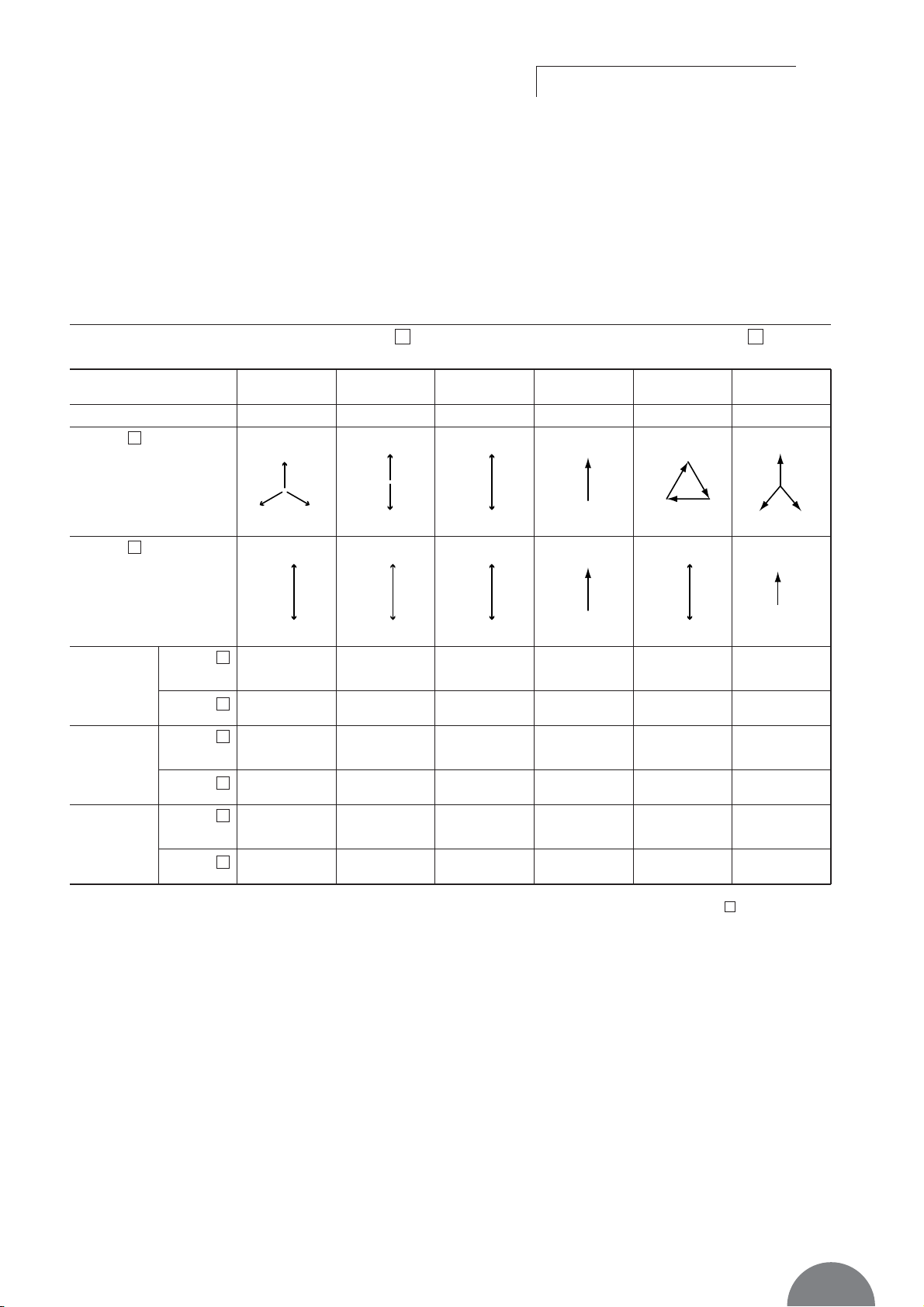
Programming and connections ATyS C30
ATyS integrates all identified networks in his programm.
It is necessary to verify this parameter before use.
THREE PHASES SENSING ON SOURCE - SINGLE PHASE SENSING ON SOURCE
21
Prog. ATyS
Source
(active
connectors)
1
Source
(active
connectors)
2
Sensing
parameters
available
U12, U23, U31,
U1, U2, U3
U31
13131
3
1
N
1
3
1
N
1
32
N
1
2
313
1
N
1
3
2
1
N
2
3
U12, U23,
U31
U31
U12, U23,
U31
U31
U12 = U23 =
U31 = 240 V
240 V
U31 = 240 V
240 V
U31 = 240 V
240 V
U1 = 240 V
240 V
U12 = U23 =
U31 = 240 V
240 V
U1 = U2 =
U3 = 240 V
240 V
U12, U23,
U31
U31
U31
U31
U1
U1
U12, U23,
U31
U31
U1, U2, U3
U1
U31
U31
U1
U1
U12, U23,
U31
U31
U1, U2, U3
U1
Controls
Example
Un = 240 V
4NBL 2NBL 2 BL 1BL* 3NBL 41NBL
3 phases
4 wires
1 phase
3 wires
1 phase
2 wires
1 phase
1 wire
3 phases
3 wires
3 phases
Source
1
Source
2
Source
1
Source
2
Source
1
Source
2
* to power supply the product, make a strap between 103 (N) and 104 terminals (input power supply 104-106 on source ).
1
Page 34

SOCOMEC - Ref.: 532 214 C - 07/05
This document is not a contract. SOCOMEC reserves the right to
modify features without prior notice in view of continued improvement.
HEAD OFFICE
SOCOMEC GROUP SWITCHING PROTECTION & UPS
S.A. capital 10 836 600 €
R.C. Strasbourg 548500 149 B
1, Rue de Westhouse - B.P. 10 - F-67235 Benfeld Cedex - FRANCE
SALES MANAGEMENT DIVISION
SOCOMEC
95, rue Pierre Grange
94132 Fontenay-sous-Bois Cedex
Tél. +33 01 45 14 63 90
Fax +33 01 45 14 63 38
www.socomec.com
QUAT NOT 3i
 Loading...