

Page 1

MAN 06 033774 – technical_guide_ DIRIS_A40_A41_C.doc40/Z41 - B 1/27
TECHNICAL GUIDE
DIRIS A40/A41
Page 2

MAN 06 033774 – technical_guide_ DIRIS_A40_A41_C.doc40/Z41 - B 2/27
SUMMARY
1 – PULSE OUTPUTS MODULE ______________________________________________________ 3
1.1 - Application : _________________________________________________________________ 3
2 – 2 ANALOG OUTPUTS MODULE ___________________________________________________ 4
2.1- Application : __________________________________________________________________ 4
3 – 2 INPUTS / 2 OUTPUTS MODULE _________________________________________________ 7
3.1- Operation of outputs in monitoring (alarms) ________________________________________ 7
3.2- Operation of outputs in command ________________________________________________ 9
3.3- Use of the input for pulses counting _____________________________________________ 11
3.3- Use of inputs for control position ________________________________________________ 12
4 – RS 485 JBUS/MODBUS COMMUNICATION MODULE _________________________________ 13
4.1 - Reading of electrical values on 2 words with HEX 300 table __________________________ 14
4.2 - reading of electrical values on 1 words with HEX 700 _______________________________ 18
4.3 - Modification of DIRIS configuration with “writing” function. _________________________ 21
5 – MEMORY MODULE _______________________________________________________ 22
5.1. Powers demands configuration (P+/P-/Q+/Q-) ______________________________________ 22
5.2. Configuration of voltage dips function (SAG) ______________________________________ 25
Page 3
MAN 06 033774 – technical_guide_ DIRIS_A40_A41_C.doc40/Z41 - B 3/27
CHAPTER 1: PULSE OUTPUTS MODULE
The DIRIS A can be equipped with 2 pulse outputs modules easily affected to active energy in kWh (EA±), reactive in kvarh (ER±)
and apparent in kVAh (ES).
The pulse outputs are configurable, with a rate of pulses of 0,1k; 1k; 10k; 100k or 1000k, and a pulse duration from 100 ms to 900
ms.
1.1 - Application:
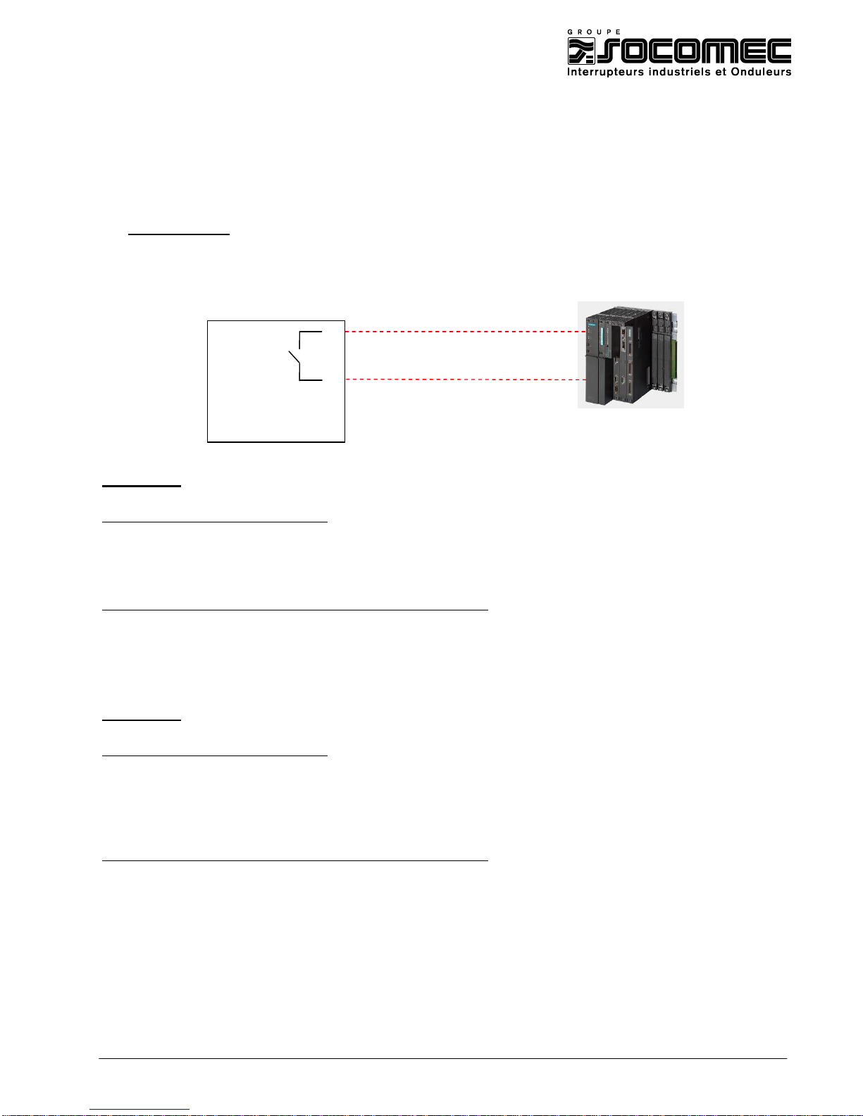
Visualisation of positive active energy meter kWh (EA+) with PLC.
It is recommended not to exceed 1 pulse per second.
Example 1: Instantaneous power displayed by the DIRIS: 105kW
Calculation of the minimum pulse rate:
105 000 W / 3600 s = 29,17W/s
In this case a pulse weight of 100 Wh can be chosen.
DIRIS configuration (see instruction manual: 876 584 or 876 585):
Pulse output type : OUT 1 TYPE = EA+ (positive active energy)
Pulses weight = Out 1 VAL = 0,1 (0,1 kWh)
Pulses duration = Out 1 DUR = 100 (100 ms)
Example 2 : Instantaneous power displayed by the DIRIS: 1895 kW
Calculation of the minimum pulse rate:
1 895 000W / 3600s = 526.3W/s
In that example, a pulse weigh of 100Wh would be too low (that would mean 5 to 6 impulses per second) it is
necessary to program a pulse weigh of 1kWh.
DIRIS configuration (see instruction manual: 876 584 or 876 585):
Pulse output allocation : OuT 1 TYPE = EA+ (positive active energy)
Pulses weight = Out 1 VAL = 1 (1kWh)
Pulses duration = Out 1 DUR = 100 (100ms)
1
2
DIRIS A40
OUT 1
PLC
Page 4
MAN 06 033774 – technical_guide_ DIRIS_A40_A41_C.doc40/Z41 - B 4/27
CHAPTER 2: 2 ANALOG OUTPUTS MODULE
The DIRIS A can be fitted with 1 or 2 analogue (0/4–20mA) outputs module. Each module has 2 analogue outputs.
Each output can be assigned to the following values: 3I, In, 3U, 3V, F, P±, Q±, S, PF
L/C
.
On each output, it is possible to configure the value for 0, 4 and 20mA.
2.1- Application:
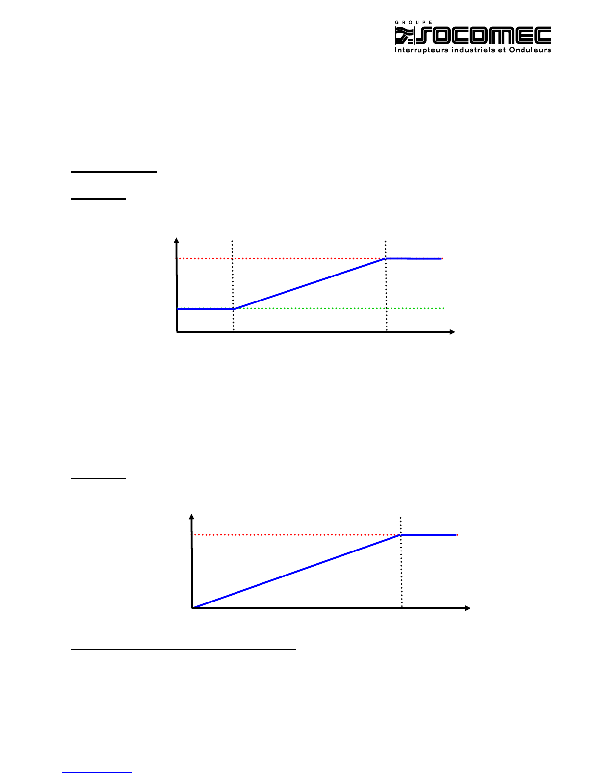
Example 1: Configuration of output 1 on current I1 with 100A at 4mA and 2500A at 20mA.
DIRIS configuration (see instruction manual : 876 586):
Analogue output type = Out 1 20mA TYPE = 4/20 (4 to 20mA)
Analogue output allocation = Out 1 20mA PAR = I1 (current phase 1)
Value at 4mA = Out 1 20mA LV = 0100 / A (100A)
Value at 20mA = Out 1 20mA HV = 2500 / A (2500A)
Example 2: Configuration of output 2 on total active power P with 0kW at 0mA and
1500kW at 20mA.
DIRIS configuration (see instruction manual : 876 586):
Analogue output type = Out 2 20mA TYPE = 0/20 (0 to 20mA)
Analogue output allocation = Out 2 20mA PAR = P (total active power)
Value at 0mA = Out 2 20mA LV = 0000 k W (0kW)
Value at 20mA = Out 2 20mA HV = 1500 k W (1500kW)
100 A
2500 A
20 mA
4 mA
20mA
0mA
1500kW
0kW
Page 5
MAN 06 033774 – technical_guide_ DIRIS_A40_A41_C.doc40/Z41 - B 5/27
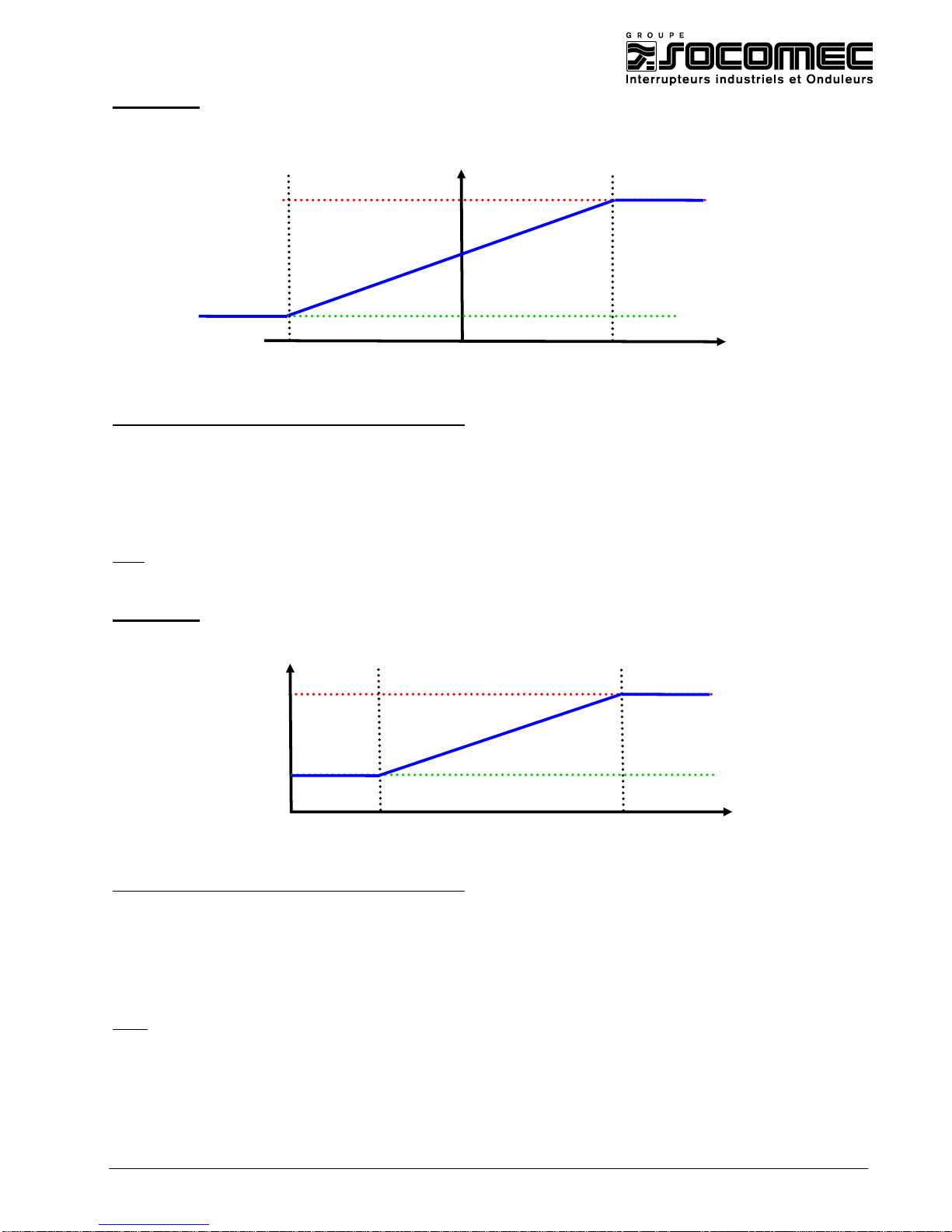
Example 3 : Configuration of output 2 on total active power P with -1000kW at 4mA and
1000kW at 20mA.
DIRIS configuration (see instruction manual: 876 586):
Analogue output type = Out 2 20mA TYPE = 4/20 (4 to 20mA)
Analogue output allocation = Out 2 20mA PAR = P (total active power)
Value at 4mA = Out 2 20mA LV = 1000 kW (-1000kW)
Value at 20mA = Out 2 20mA HV = 1000 kW (1000kW)
Note: To use the analogue output with positive and negative values at the same time, it is necessary to program identical values
for LV and HV.
Example 4: Configuration of output 3 on frequency F with 45Hz at 4mA and 55Hz at 20mA.
DIRIS configuration (see instruction manual: 876 586):
Analogue output type = Out 2 20 mA TYPE = 4/20 (4 to 20mA)
Analogue output allocation = Out 2 20 mA PAR = F (frequency)
Value at 4 mA = Out 2 20 mA LV = 4500 (45Hz)
Value at 20 mA = Out 2 20 mA HV = 5500 (55Hz)
Note: For the frequency, the values for 4mA and 20mA must be programmed on 4 digits; therefore, for 45Hz enter
the value 4500.
20mA
4mA
1000kW
- 1000kW
12mA
20mA
4mA
45Hz
55Hz
Page 6
MAN 06 033774 – technical_guide_ DIRIS_A40_A41_C.doc40/Z41 - B 6/27
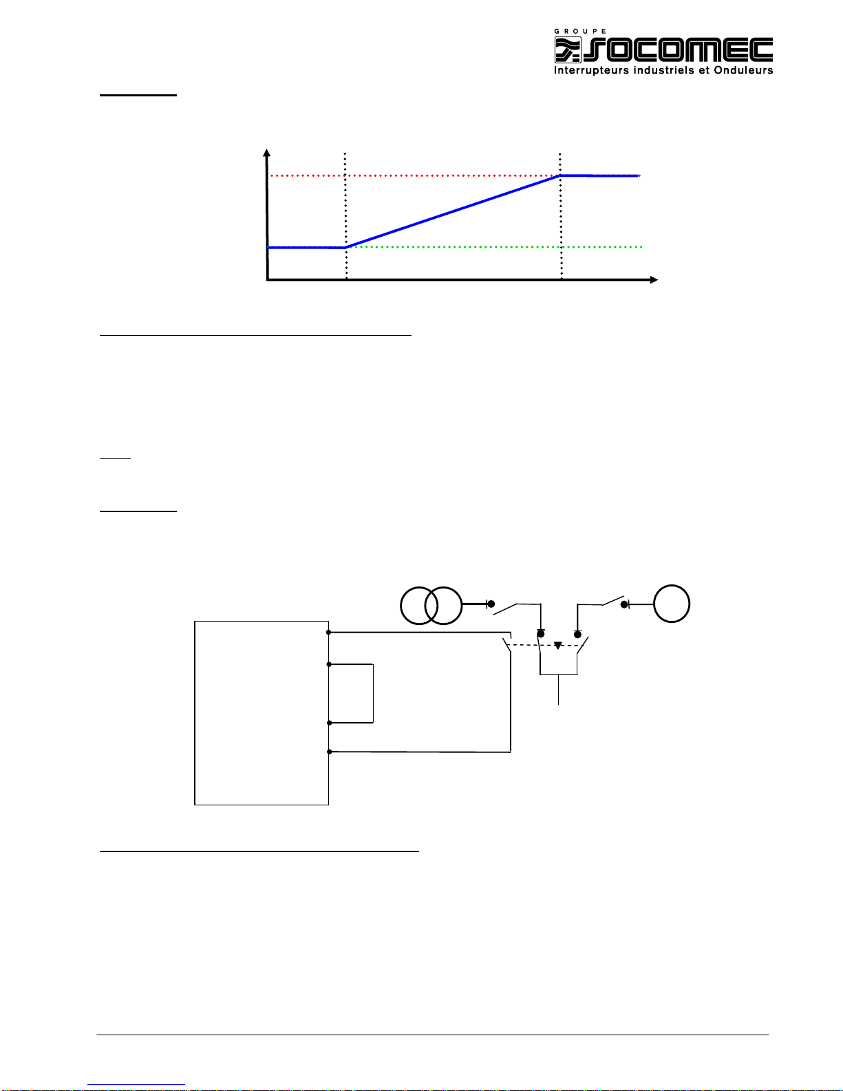
Example 5: Configuration of output 4 on inductive power factor PFL with 0,5 for 4mA and
1 for 20mA.
DIRIS configuration (see instruction manual: 876 586):
Analogue output type = Out 2 20 mA TYPE = 4/20 (4 to 20mA)
Analogue output allocation = OUt 2 20 mA PAR = PFL (inductive power factor)
Value at 4mA = Out 2 20 mA LV = 500 (0,5)
Value at 20mA = Out 2 20 mA HV = 1000 (1)
Note: For the power factor, the values for 4 and 20mA must be programmed on 3 digits; therefore, for 0,5 enter the
value 500.
Example 6: Configuration of the analogue output 1 to provide a 30VDC optocoupler
supply to use with the inputs / outputs module . For example, to count the
number of changeover operations or control position (see §3.3)
DIRIS configuration (see instruction manual : 876 586) :
Analogue output type = Out 1 20mA TYPE = 30 V (30VDC)
20mA
4mA
0,5
1
5+
6-
13
14
DIRIS A40
OUT 1
4-20 mA
IN 1
Ge
Page 7
MAN 06 033774 – technical_guide_ DIRIS_A40_A41_C.doc40/Z41 - B 7/27
CHAPTER 3: 2 INPUTS / 2 OUTPUTS MODULE
The DIRIS A can be fitted with 1,2 or 3 IN/OUT module. Each module has 2 inputs and 2 outputs.
The outputs can be used to monitor electrical values or to command equipments.
The inputs can be used for pulses metering or to control equipments status.
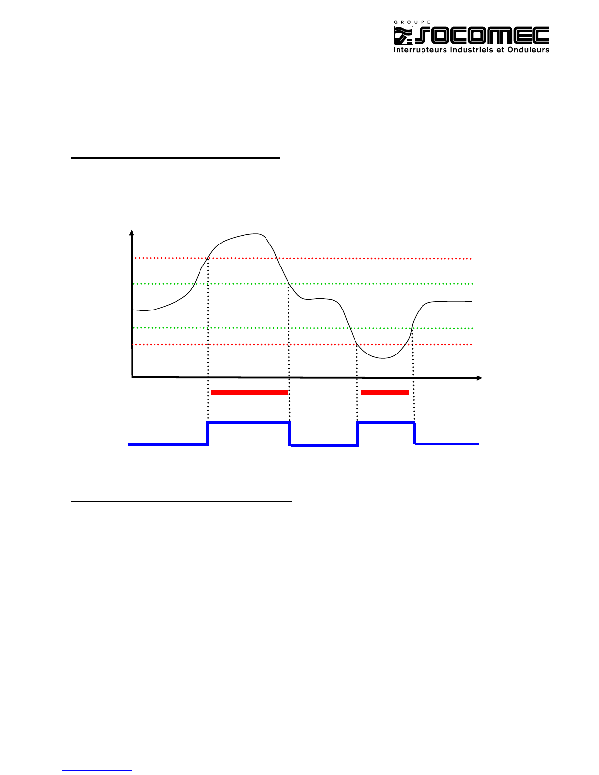
3.1- Output used as monitoring (alarms)
Example 1 : Configuration of relay output N°1 to monitor the currents (3I) with alarm if
I<100A or I>800A. Further parameters: 10 % hysteresis, relay status NO and
without temporisation.
DIRIS configuration (see instruction manual: 876 587):
Relay output 1 type = OuT 1 A-Cd TYPE = I (alarm on current)
Alarm : upper threshold = Out 1 Ht I 0800 / A (800A)
Alarm : lower threshold = Out 1 Lt I 0100 / A (100A)
Hysteresis = Out 1 HYST 10 (10%)
Relay time delay = Out 1 TEMPO 000 (0 second)
Relay status = Out RELAY NO (Normally Open)
800A
100A
720A
110A
ALARM
ALARM
0
1 0 1
Relay
status
Page 8
MAN 06 033774 – technical_guide_ DIRIS_A40_A41_C.doc40/Z41 - B 8/27
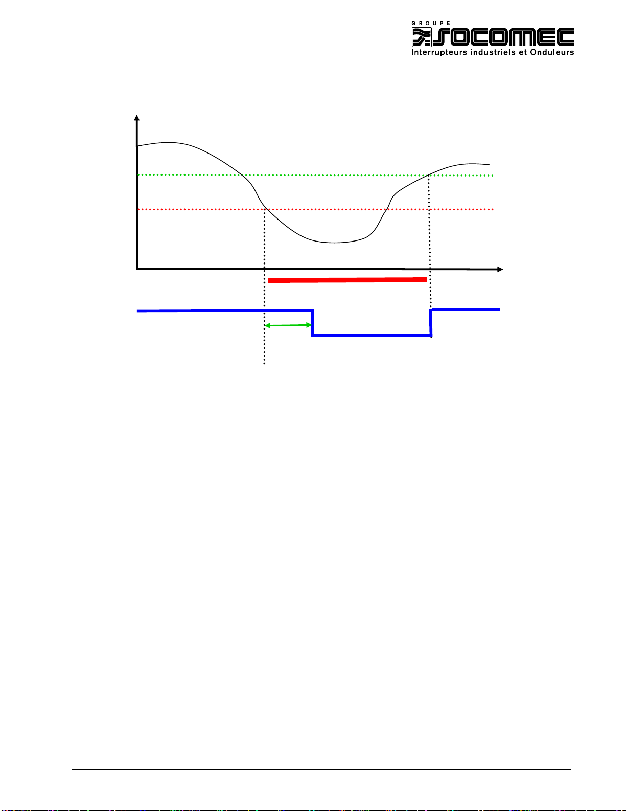
Example 2 : Configuration of relay output N°2 to monitor the phase to neutral voltage with
alarm if V<200v, without upper threshold. Further parameters: 5 % hysteresis,
relay status NC and 10s temporisation.
DIRIS configuration (see instruction manual: 876 587):
Relay output 1 type = OuT 2 A-Cd TYPE = V (alarm on voltage)
Alarm : upper threshold = Out 2 Ht I 0300 / V (300V to make sure that level will never be reached in order to inhibit
the upper threshold)
Alarm : lower threshold = Out 2 Lt I 0200 / V (200V)
Hysteresis = Out 2 HYST 05 (5%)
Relay time delay = Out 2 TEMPO 010 (10 seconds)
Relay status = Out RELAY NC (Normally closed)
210V
200V
ALARM
1 0 1
Time
delay
=10s
Relay
state
Page 9
MAN 06 033774 – technical_guide_ DIRIS_A40_A41_C.doc40/Z41 - B 9/27
3.2- Outputs used as command
This function is used with RS85 JBUS/MODBUS or PROFIBUS-DP communication module. Through the
communication, it is possible to change the status of the Diris outputs.
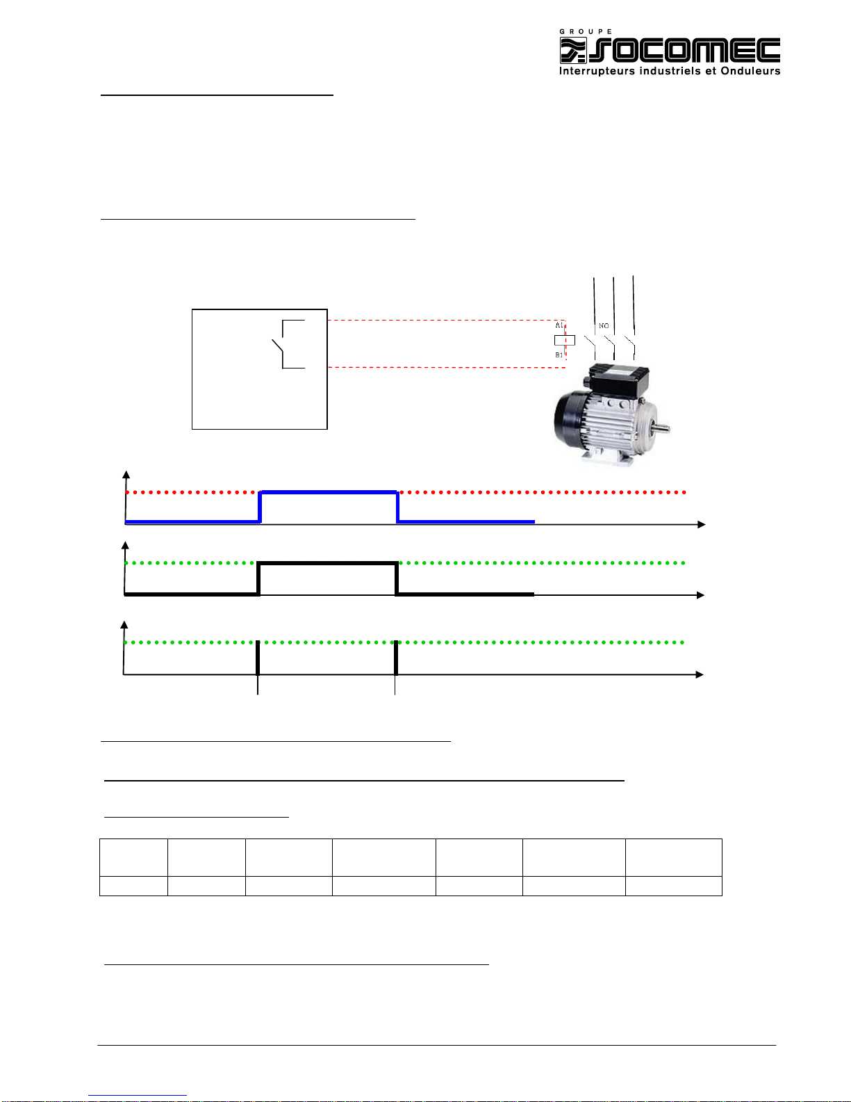
Example 1: Changing the relay 1 status to start an engine remotely.
DIRIS configuration (see instruction manual: 876 587):
Relay output 1 type = OuT 1 A-Cd TYPE = CdE (Command)
JBUS/MODBUS frame (see instruction manual : CDR27028)
Changing the relay output N°1(addresses Hex. 22E) closed = 1 and opened = 0
Master frame to close the relay:
Slave
Function
Address
Address
Value
Value
CRC16
High-order
High-order
High-order
Low-order
05
06
02
2E
00
01
283F
Closed start
motor
The response of the DIRIS is identical to the request of the Master
9
10
DIRIS A40
OUT 1
Motor
Communication
Address 22E = 1
Address 22E = 0
OFF
ON
OFF
Relay
0 0 1
Page 10
MAN 06 033774 – technical_guide_ DIRIS_A40_A41_C.doc40/Z41 - B 10/27
Changing the relay output N°1(addresses Hex. 22E) closed = 1 and opened = 0
Master frame to open the relay:
Slave
Function
Address
Address
Value
Value
CRC16
High-order
High-order
High-order
Low-order
05
06
02
2E
00
00
E9FF
Open
Stop motor
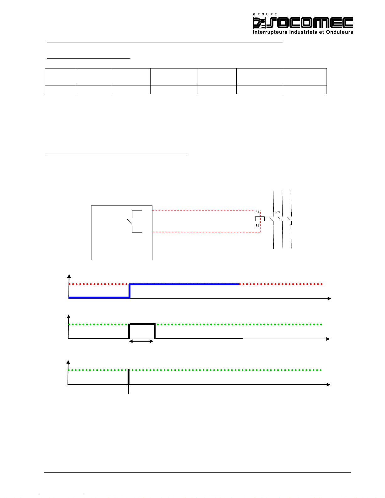
Example 2 : Changing the relay 1 status to give a 3 seconds order to initiate a process
(same function as a pushbutton). Normally open relay run mode.
DIRIS configuration (see instruction manual: 876 587):
Relay output 1 type = Out 1 A-Cd TYPE = Cd-t (temporised command)
Temporisation before return to rest state =Out 1 TEMPO 003 (3 seconds)
Relay status = Out 1 RELAY NO (Normally open)
Process
OFF
ON
Relay
0 0 1
Communication
Address 22E = 1
TEMPO
=
3s
9
10
DIRIS A40
OUT 1
Page 11
MAN 06 033774 – technical_guide_ DIRIS_A40_A41_C.doc40/Z41 - B 11/27
JBUS/MODBUS frame (see instruction manual : CDR27028)
Changing the relay output N°1(addresses Hex. 22E) closed = 1 and opened = 0
Master frame to close the relay:
slave
Function
Address
Address
Value
Value
CRC16
High-order
High-order
High-order
Low-order
05
06
02
2E
00
01
283F
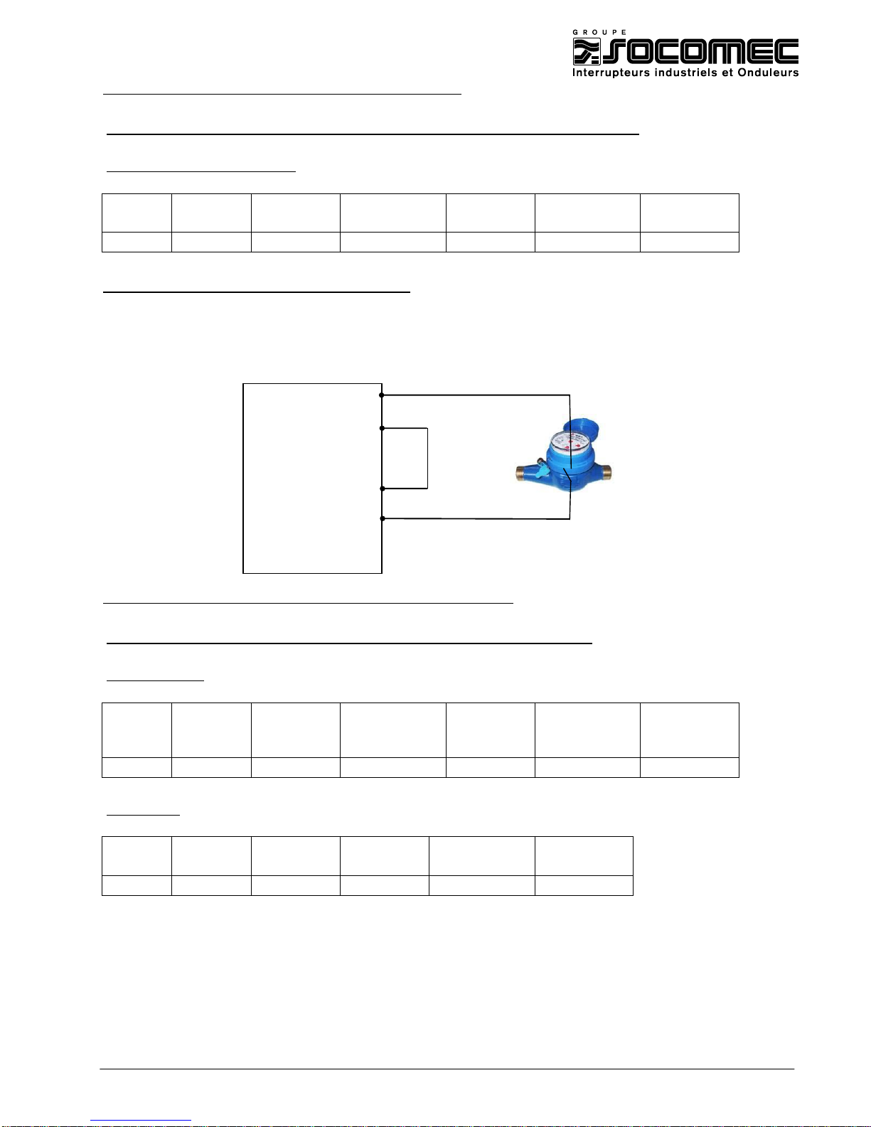
3.3- Use of the input for pulses metering
Example 1 : Input 1 used to count the pulses from a flow meter. The E1 meter can be
visualised on the DIRIS’ display and through the communication module.
Visualisation by JBUS/MODBUS (see instruction manual CDR27028)
Visualisation of the meter E1 status = 4967733 (Adress Hex 735 et 736)
Master request :
Slave
Function
Address
Address
Number of
words
Number of
words
CRC16
High-order
High-order
High-order
Low-order
05
03
07
35
00
02
75D
DIRIS reply:
Slave
Function
Number of
Word 1
Word 2
CRC16
bytes
05
03
04
1E35
01F0
A801
7733 496
The Diris’ answer must be interpreted this way:
496 * 10000 + 7733 = 6 490 458 pulses
5+
6-
13
14
DIRIS A40
OUT 1
4-20 mA
IN 1
Page 12
MAN 06 033774 – technical_guide_ DIRIS_A40_A41_C.doc40/Z41 - B 12/27
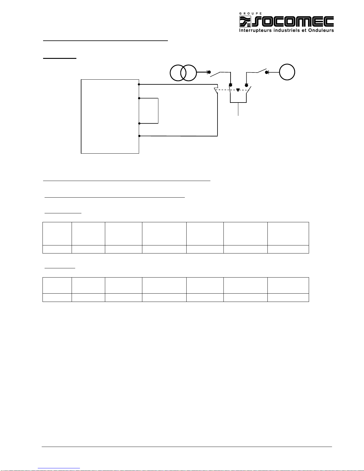
3.3- Use of the input to control position
Example 1 : Control position (status) of a changeover switch.
Command by JBUS/MODBUS (see instruction manual: CDR27028)
Visualisation of Input 1 status (address HEX 36E )
Master request
Slave
Function
Address
Address
Number of
words
Number of
words
CRC16
High-order
Low-order
High-order
Low-order
05
03
03
6E
00
02
A416
DIRIS reply:
Slave
Function
Address
Address
Word 1
Word 2
CRC16
High-order
Low-order
05
03
02
2E
0001
0000
EE33
INPUTS
Input 1
active
OUTPUTS
5+
6-
13
14
DIRIS A40
OUT 1
4-20 mA
IN 1
Ge
Page 13

MAN 06 033774 – technical_guide_ DIRIS_A40_A41_C.doc40/Z41 - B 13/27
CHAPTER 4 – RS 485 JBUS/MODBUS COMMUNICATION MODULE
The DIRIS A can be fitted with an RS485 JBUS/MODBUS communication module.
This module allows programming and visualizing the electrical values displayed by the DIRIS with a PC, a PLC or any other
system.
The RS485 connection is wired in series according to the EIA 485 with 2 active wire (+, -).
One RS485 line allows the connection of 31 slaves (DIRIS) over a distance of 1500 meters at 9600 bauds.
The number of slaves can be increase by using repeater(s), however, the maximum of slaves is 255 by communication canal.
It is recommended to use twisted pair type cable (LIYCY type ; minimum section: 0,34mm²). In a disturbed
environment or large network (in terms of length) we recommend using 1 shielded pair type LIYCY-CY (minimum
section: 0,34mm²).
Communication frame:
The standard communication frame is following:
Slave address
Function code
Address
Data
CRC 16
According to the JBUS/MODBUS protocol, the transmission time must be less than 3 silences, i.e. the emission time
of 3 characters so that the message is processed by the DIRIS.
The available functions code are following:
- 3 : to read n words (maximum 128)
- 6 : to write one word
- 8 : to diagnose exchanges between the master and the slave via meters 1 ,2, 4, 5 and 6.
- 16 : to write n words (maximum 128)
-
The response time (time out question/answer) is 250 ms maximum.
Page 14

MAN 06 033774 – technical_guide_ DIRIS_A40_A41_C.doc40/Z41 - B 14/27
4.1 - Reading of electrical values on 2 words with HEX 300 table
Reading of current phase 1 (address Hex. 300) : I1 = 236,7 A
DIRIS A JBUS/MODBUS address : 7
Master request :
Slave
Function
Address
Address
Number of words
Number of words
CRC16
High-order
Low-order
High-order
Low-order
07
03
03
00
00
02
C429
DIRIS reply:
Slave
Function
Number of
Word1
Word 2
CRC16
bytes
07
03
04
0003
9C9C
055A
236 700 mA
Reading of phase to phase voltage U12 (address Hex. 308) : U12 = 398,9 V AC
Master request :
Slave
Function
Address
Address
Number of words
Number of words
CRC16
High-order
Low-order
High-order
Low-order
07
03
03
0E
00
02
A5EA
DIRIS reply:
Slave
Function
Number of
Word1
Word 2
CRC16
bytes
07
03
04
0000
9BD5
A3F6
39 893 mV
Reading of total active power (address Hex. 316) : P1 = + 158,78 kW
Master request :
Slave
Function
Address
Address
Number of words
Number of words
CRC16
High-order
Low-order
High-order
Low-order
07
03
03
16
00
02
25ED
DIRIS reply:
Slave
Function
Number of
Word1
Word 2
CRC16
bytes
07
03
04
0000
3E06
0C51
15 878 kW/100
Page 15

MAN 06 033774 – technical_guide_ DIRIS_A40_A41_C.doc40/Z41 - B 15/27
Reading of total active power (address Hex. 316) : P1 = - 1729 kW
Master request :
Slave
Function
Address
Address
Number of words
Number of words
CRC16
High-order
Low-order
High-order
Low-order
07
03
03
16
00
02
25ED
DIRIS reply:
Slave
Function
Number of
Word1
Word 2
CRC16
bytes
07
03
04
FFFD
5C89
5D06
4 294 794 377 kW/100
If the answer corresponds to a negative value, the answer, in decimal value, will be higher
than 2147 483 647.
In that case, it is necessary to convert the value in the following way:
First step: convert the value Hexadecimal into binary
Hexadecimal :
FFFD5C89
Binary :
1111 1111 1111 1101 0101 1100 1000 1001
Second step: reverse the binary value
Binary :
1111 1111 1111 1101 0101 1100 1000 1001
opposite :
0000 0000 0000 0010 1010 0011 0111 0110
Third step: Add + 1
opposite :
0000 0000 0000 0010 1010 0011 0111 0110
+1
Binary :
0000 0000 0000 0010 1010 0011 0111 0111
Last step: convert in decimal to get the final result
Binary :
0000 0000 0000 0010 1010 0011 0111 0111
Decimal :
172919 kW/100
Page 16

MAN 06 033774 – technical_guide_ DIRIS_A40_A41_C.doc40/Z41 - B 16/27
Reading of power factor phase 1 (address Hex. 330) : PF1 = 0,99 Inductive
Master request :
Slave
Function
Address
Address
Number of words
Number of
words
CRC16
High-order
Low-order
High-order
Low-order
07
03
03
30
00
02
C426
DIRIS reply::
Slave
Function
Number of
Word1
Word 2
CRC16
bytes
07
03
04
0000
03E7
DC89
999 /1000
Reading of power factor phase 1 (address Hex. 330) : PF1 = 0,94 Capacitive
Master request :
Slave
Function
Address
Address
Number of words
Number of
words
CRC16
High-order
Low-order
High-order
Low-order
07
03
03
30
00
02
C426
DIRIS reply:
Slave
Function
Number of
Word1
Word 2
CRC16
bytes
07
03
04
FFFF
FC54
DCE8
4294966356 / 1000
If the answer corresponds to a negative value, the answer, in decimal value, will be higher
than 1000.
In that case, it is necessary to convert the value in the following way:
First step: convert the value Hexadecimal into
binary
Hexadecimal :
FFFFFC54
Binary :
1111 1111 1111 1111 1111 1100 0101 0100
Second step: reverse the binary
value :
Binary :
1111 1111 1111 1111 1111 1100 0101 0100
opposite :
0000 0000 0000 0000 0000 0011 1010 1011
Third step: Add + 1
opposite :
0000 0000 0000 0000 0000 0011 1010 1011
+1
Page 17
MAN 06 033774 – technical_guide_ DIRIS_A40_A41_C.doc40/Z41 - B 17/27
Binary :
0000 0000 0000 0000 0000 0011 1010 1100
Last step: convert in decimal
Binary :
0000 0000 0000 0000 0000 0011 1010 1100
Decimal :
940 /1000
Reading of positive active energy meter Lecture du compteur d'énergie active + (adresse
Hex. 358) : Ea + = 06490374 kWh
Master request :
Slave
Function
Address
Address
Number of words
Number of
words
CRC16
High-order
Low-order
High-order
Low-order
07
03
03
58
00
02
45FA
DIRIS reply:
Slave
Function
Number of
Word1
Word 2
CRC16
bytes
07
03
04
0063
0906
7D37
6490374 kWh
Page 18

MAN 06 033774 – technical_guide_ DIRIS_A40_A41_C.doc40/Z41 - B 18/27
4.2 - reading of electrical values on 1 word with HEX 700
DIRIS A JBUS/MODBUS address : 7
With current transformer ratio = CT =100/5 A and voltage transformer = VT =
1000/100 V AC
Reading of current phase 1 (address Hex. 700) :I1 = 100,7 A
Master request :
Slave
Function
Address
Address
Number of words
Number of words
CRC16
High-order
Low-order
High-order
Low-order
07
03
07
00
00
01
C429
DIRIS reply:
Slave
Function
Number of
Word 1
CRC16
bytes
07
03
02
13AC
055A
5036 mA
It is necessary to convert the answer in the following way:
multiply by CT ratio
5036 mA x 100/5 = 100 720 mA =100,72 A
Reading of phase to phase voltage U12 (address Hex. 704) : U12 = 1055 V AC
Master request :
Slave
Function
Address
Address
Number of words
Number of words
CRC16
High-order
Low-order
High-order
Low-order
07
03
07
04
00
01
C4D9
DIRIS reply:
Slave
Function
Number of
Word 1
CRC16
bytes
07
03
02
2938
2E06
10 552 V/100
It is necessary to convert the value in the following way:
multiply by VT ratio :
10 552 x 1000/100 = 105 520 V/100 = 1055,2 V AC
Page 19

MAN 06 033774 – technical_guide_ DIRIS_A40_A41_C.doc40/Z41 - B 19/27
Reading of total active power (address Hex. 70B) : P1 = + 425,6 kW
Master request :
Slave
Function
Address
Address
Number of words
Number of words
CRC16
High-order
Low-order
High-order
Low-order
07
03
07
0B
00
01
F4DA
DIRIS reply:
Slave
Function
Number of
Word 1
CRC16
bytes
07
03
02
0850
37B8
2128 kW/100
It is necessary to convert the value in the following way:
multiply by VT*CT ratio
2128*100/10*100/5= 425 600 kW/100 = 425,6 kW
Reading of total active power (address Hex. 70B): P1 = - 332,2 kW
Master request :
Slave
Function
Address
Address
Number of words
Number of words
CRC16
High-order
Low-order
High-order
Low-order
07
03
07
0B
00
01
F4DA
DIRIS reply:
Slave
Function
Number of
Word 1
CRC16
bytes
07
03
02
F983
33B5
63875 kW/100
If the answer corresponds to a negative value, the answer, in decimal value, will be higher
than 32767.
In that case, it is necessary to convert the value in the following way:
First step: convert the value Hexadecimal into binary
Hexadecimal :
F983
Binary :
1111 1001 1000 0011
Second step: reverse the binary
value
Binary :
1111 1001 1000 0011
opposite :
0000 0110 0111 1100
Page 20

MAN 06 033774 – technical_guide_ DIRIS_A40_A41_C.doc40/Z41 - B 20/27
Third step: Add + 1
opposite :
0000 0110 0111 1100
+1
Binary:
0000 0110 0111 1101
Fourth step: convert in decimal
Binary :
0000 0110 0111 1101
Decimal :
1661 kW/100
Last step: multiply by VT*CT ratio
1661*100/10*100/5= 332 200 kW/100 = 332,2 kW
Reading of power factor phase 1 (address Hex. 718) : PF1 = 0,99 Inductive
Master request:
Slave
Function
Address
Address
Number of words
Number of words
CRC16
High-order
Low-order
High-order
Low-order
07
03
07
18
00
01
051F
DIRIS reply:
Slave
Function
Number of
Word 1
CRC16
bytes
07
03
04
03E7
DC89
999 /1000
Reading of positive active energy meters (adsress Hex. 72B + 72C) : Ea + = 06490458kWh
Master request:
Slave
Function
Address
Address
Number of words
Nombre de mots
CRC16
High-order
Low-order
High-order
poids faible
07
03
07
2B
00
02
45FA
DIRIS reply:
Slave
Function
Number of
CRC16
bytes
Word 1
Word 2
07
03
04
01CA
0289
7D37
458
649
It is necessary to convert the value in the following way:
649 * 10000 + 458 = 6 490 458 kWh
Page 21
MAN 06 033774 – technical_guide_ DIRIS_A40_A41_C.doc40/Z41 - B 21/27
4.3 - Modification of DIRIS configuration with “writing” function.
Configuration of CT primary (address Hex. 202) : TC = 1500 = 05DC en hexadecimal
Master request:
Slave
Function
Address
Address
Value
Value
CRC16
High-order
Low-order
High-order
Low-order
07
06
02
02
05
DC
2B1D
1500 in decimal
DIRIS reply:
Identical to master request
After having modified the parameters of the DIRIS, and to record them, it is necessary to send
the backup order:
Slave
Function
Address
Address
Value
Value
CRC16
High-order
Low-order
High-order
Low-order
07
06
06
00
00
00
8924
DIRIS reply:
The DIRIS does not answer this order.
Configuration of network type (address Hex. 200) , Type = 3 NBL = 3 in hexadecimal
Master request :
Slave
Function
Address
Address
Value
Value
CRC16
High-order
Low-order
High-order
Low-order
07
06
02
00
00
03
C815
3 NBL
DIRIS reply:
The DIRIS does not answer this order.
After having modified the parameters of the DIRIS, and to record them, it is necessary to send
the saving order:
Slave
Function
Address
Address
Value
Value
CRC16
High-order
Low-order
High-order
Low-order
07
06
06
00
00
00
8924
DIRIS response:
The DIRIS does not answer this order.
Page 22
MAN 06 033774 – technical_guide_ DIRIS_A40_A41_C.doc40/Z41 - B 22/27
CHAPTER 5 – MEMORY MODULE
5.1. Powers demands configuration (P+/P-/Q+/Q-)
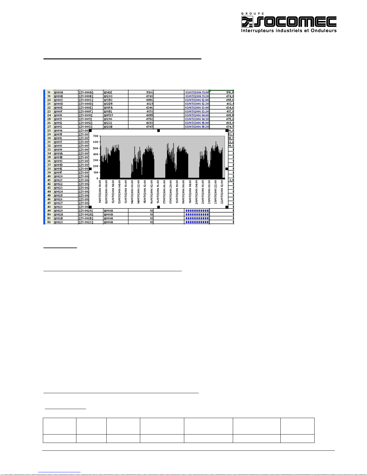
Powers demand storage (load curves) is used to store and analyse consumption of electrical distribution with date
and time.
Exemple 1: Storage of active power (kWh) integrated on 10 minutes and 62 days. With
internal synchronisation (internal clock) and reading by communication.
DIRIS Configuration (see instruction manual: 876 588) :
Memorisation of positive active power (+kWh) = MEMO P+ YES (yes)
Memorisation of negative active power (+kWh) = MEMO P- NO (no)
Memorisation of positive reactive power (+kvarh) = MEMO P+ NO (no)
Memorisation of negative reactive power (-kvarh) = MEMO P- NO (no)
Synchronisation mode = MEMO TOP EXT (external)
Configuration of synchronisation top time = MEMO TIME 10’ (10 minutes)
Activation of date/time function = dAtE tIME YES (yes)
Date configuration = dAtE 31-07-06
Time configuration = tIME 15h10’35"
Reading of date and time of update of the timekeepers
Master request :
Slave
Function
Address
Address
Value
Value
CRC16
High-order
Low-order
High-order
Low-order
01
03
30
02
00
03
AB0B
Page 23

MAN 06 033774 – technical_guide_ DIRIS_A40_A41_C.doc40/Z41 - B 23/27
DIRIS response:
Salve
Function
Number of
Word 1
Word 2
Word 3
CRC16
bytes
01
03
06
071F
100A
0006
11C0
07 31
10 0A
0006
July the 31th
16 h 10 minutes
00 secondes
year 2006
Reading of timekeeper for active powers P+/P- of last value
Master request :
Slave
Function
Address
Address
Value
Value
CRC16
High-order
Low-order
High-order
Low-order
01
03
30
00
00
01
8B0A
DIRIS response:
Salve
Function
Number of
Word 1
CRC16
bytes 01
03
02
004C
B9B1
Reading of last power average value on 3051 address (address 3005 + timekeeper address)
Master request :
Slave
Function
Address
Address
Value
Value
CRC16
High-order
Low-order
High-order
Low-order
01
03
30
51
00
01
DADB
Adr. 3005 + 4C = 3051
DIRIS response:
Salve
Function
Number of
Word 1
CRC16
bytes 01
03
02
16FA
3667
= 5882 in décimal without CT and VT ratio
= 5882 * (10000/5A) = 11 764 000
= 1176,4 kW on the interval 10 minutes of 4:10 pm
Page 24
MAN 06 033774 – technical_guide_ DIRIS_A40_A41_C.doc40/Z41 - B 24/27
Address Hex
Decimal value
(W/10)
Date and time
Value without
CT and VT ratio
(W)
Value multiply
by CT and VT
ration (W)
TC = 10000/5
… … … … …
304D
5828
31/07/06 15 :30 :00
582.8
1165600
304E
4796
31/07/06 15 :40 :00
476.6
953200
304F
3597
31/07/06 15 :50 :00
359.7
719400
3050
5467
31/07/06 16 :00 :00
546.7
1093400
3051
5882
31/07/06 16 :10 :00
588.2
1176400
NB :
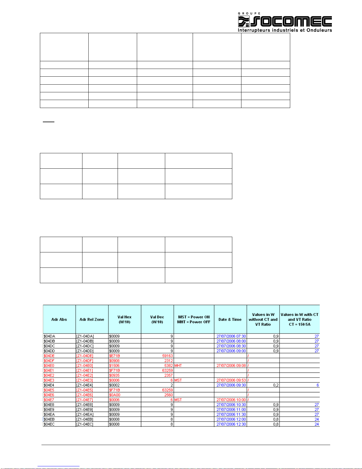
When DIRIS is switch off (MHT), this information is coded in the following way
First word star always with $Exxx
Adress + 0
$Emdd
1 word
m : month 1 to 12
dd : day 1 to 31
Adress + 1
$hhnn
1 word
hh : hours 0 to 23
nn : minutes 0 to 60
Adress + 2
$ssyy
1 word
ss : secondes 0 to 59
yy : year 0 à 255
When DIRIS is switch on (MST), this information is coded in the following way
First word star always with $Fxxx
Adress + 0
$Fmdd
1 word
m : month 1 to 12
dd : day 1 to 31
Adress + 1
$hhnn
1 word
hh : hours 0 to 23
nn : minutes 0 to 60
Adress + 2
$ssyy
1 word
ss : secondes 0 to 59
yy : year 0 à 255
The recorded average power, between DIRIS starting and the following interval of time, is framed by two MST. See
below :
Page 25
MAN 06 033774 – technical_guide_ DIRIS_A40_A41_C.doc40/Z41 - B 25/27
5.2. Configuration of voltage dips function (SAG)
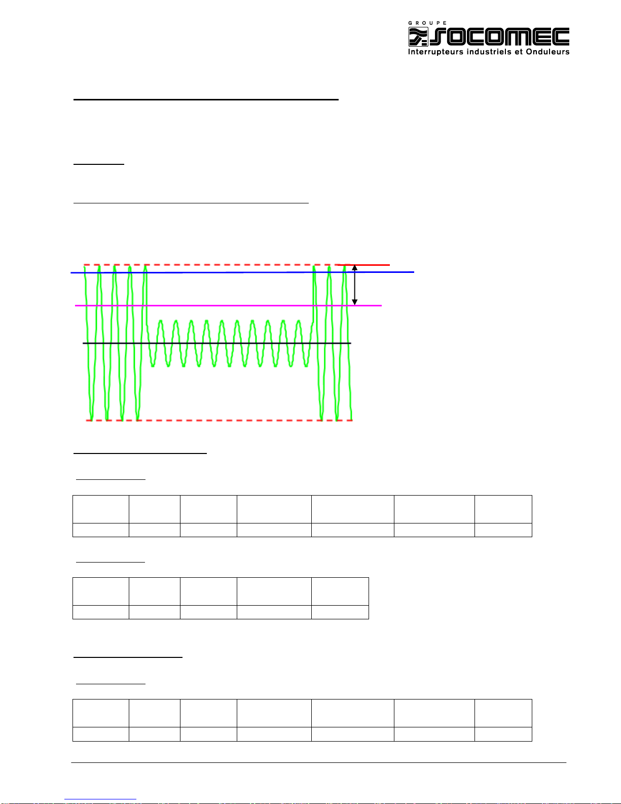
This function is used to detect voltage dips according to EN 50160 standard (Voltage characteristics of electricity
supplied by public distribution systems)
Example : Discover voltage dips ( SAG) with a threshold in 10 % and a hysteresis of 2
%. Reading information with communication
DIRIS configuration (see instruction manual : 876 588) :
Voltage dips threshold (SAG) = dAtA SAG 10 % )
Voltage dips hysteresis = dAta HySt SAG 2 %
Reading of fault parameter:
Master request :
Slave
Function
Address
Address
Value
Value
CRC16
High-order
Low-order
High-order
Low-order
01
03
0D
00
00
01
86A6
DIRIS response:
Salve
Function
Number of
Word 1
CRC16
bytes 01
03
02
0005
7847
5 = U12
Reading of fault value:
Master request :
Slave
Function
Address
Address
Value
Value
CRC16
High-order
Low-order
High-order
Low-order
01
03
0D
01
00
02
86A6
= 10 %
Un
Threshold (Un – 10 % de Un)
Hysteresis (Un – 2% de Un)
Page 26

MAN 06 033774 – technical_guide_ DIRIS_A40_A41_C.doc40/Z41 - B 26/27
DIRIS response:
Salve
Function
Nombre
Word 1
Word 2
CRC16
d'octets
01
03 4 0000
0000
FA33
0 V
Reading of voltage dips duration :
Master request :
Slave
Function
Address
Address
Value
Value
CRC16
High-order
Low-order
High-order
Low-order
01
03
0D
06
00
02
86A6
DIRIS reply:
Salve
Function
Number of
Word 1
Salve
CRC16
bytes
01
03 4 0000
03A2
7B7A
Dec = 932 seconds
Lecture de la date et de l’heure du creux :
Master request ::
Slave
Function
Address
Address
Value
Value
CRC16
High-order
Low-order
High-order
Low-order
01
03
0D
08
00
06
46A6
DIRIS reply:
Number of
Salve
Number of
Word 1
Word 2
Word 3
Word 4
Word 5
bytes
01
03
12
000F
0007
0006
000E
0022 31
07
06
14
Dec = 34
31
July
2006
14h
34 min
word 6
CRC16
0012
xxxx
December
= 12
00 seconds
Page 27
MAN 06 033774 – technical_guide_ DIRIS_A40_A41_C.doc40/Z41 - B 27/27
5.2. Configuration of over voltage function (SWELL)
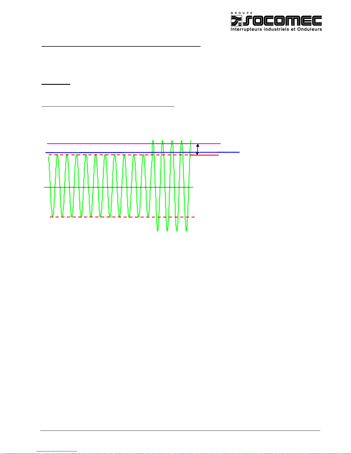
This function is used to detect over voltage according to EN 50160 standards (Voltage characteristics of electricity
supplied by public distribution systems)
Example : Discover over voltage (SWELL) with a threshold in 10 % and a hysteresis of 2
%. Reading information with communication
DIRIS configuration (see instruction manual : 876 588) :
Over voltage threshold (SWELL) = dAtA SAG 10 % )
Over voltage hysteresis = dAta HySt SAG 2 %
Reading of the information is made in the same way as for voltage dips (see 5.2)
= 10 %
Un
Threshold (Un + 10 % de Un)
Hysteresis (Un+ 2% de Un)
 Loading...