

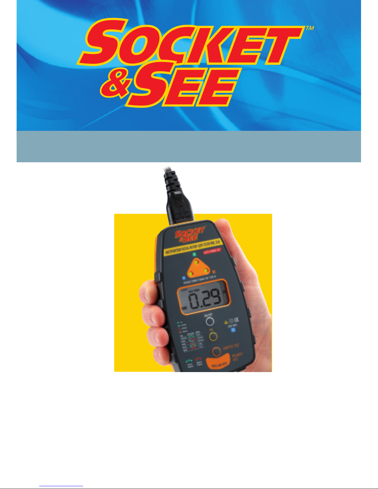
PART P MULTIFUNCTION DIGITAL LOOP TESTER
Tests no-trip loop, PFC, socket, mains voltage & polarity
PDL 310
USER MANUAL 06/06

2
Caution
We strongly advise reading and understanding this guide
before the instrument is used. In particular note the safety
issues that follow:-
l Although fully protected up to 600V AC this tester is for
use on 230V AC circuits only.
l Always check the tester on a known correctly wired live
socket outlet before and after use.
l Before use - check your tester for any damage to
the plug, lead and cabinet.
BS EN
61010-1
PDL 310
At Socket & See our Engineers constantly look for improvement.
If there is any aspect of your Socket & See tester you would like
to comment on please visit our website at
www.socketandsee.co.uk
or email davidh@kewt.co.uk or Free Fax at 0800 7831385
with any suggestions.
We promise all communications will be acknowledged.
We value YOUR opinion.
Important calibration/check box note
l Because of the Super Smart Loop Test System the test is
immune to sudden value changes (such as voltage spikes).
l As a result when changing calibration or check box loop
values the unit must be switched off between changes.

3
Operation overview
Your Socket & See tester has a special polarity test function.
It is a little known fact that a system can be reverse wired with Live (Phase) to
earth/neutral and earth/neutral to Live (Phase) The sockets will all work and
conventional loop testers will show and test that everything is correct despite
this very dangerous wiring condition.
Although extremely rare, this miswire condition can exist so if your test shows
this fault do not proceed - if in any doubt advise your customer to contact their
supply company immediately.
overview
FUSE 100A
FUSE 100A
From Supply
Company
Live (Phase)
to Meter
Neutral to Meter
To Main
Earthing
Terminal
Neutral to Meter
Live (Phase)
to Meter
To Main
Earthing
Terminal
From Supply
Company
Correct Polarity
REVERSE POLARITY
Typical Supply Service
Cut-Out Fuse
LIVE (Phase)
NEUTRAL
Typical Supply Service
Cut-Out Fuse
NEUTRAL
LIVE (Phase)
Solid Brass
Connecting
Block
Solid Brass
Connecting
Block

4
PDL 310
Operation overview continued
The PDL 310 is a multifunction tester testing for no trip loop, no-trip PFC (Prospective
Fault Current), mains voltage (L-N), correct socket wiring, and polarity.
Correct socket wiring and correct polarity
At the Socket Test stage the PDL 310 also accurately measures and displays the mains
voltage in the LCD (Liquid Crystal Display).
A reminder of the correct voltage range 207-253V AC (Harmonised Standard BS 7697
HD 42S1) is given above the display.
If the Voltage Range is outside of this standard, stop testing - your customer should notify
their electricity supply company of the problem.
If the three socket LED’s are GREEN (correct) and the correct voltage is displayed you
can proceed to Polarity Test.
The reasons for Polarity Test are covered in detail on the previous page of this User Guide.
To carry out the test apply firm (thumb) pressure to the Polarity Test Pad, note this pad
does not depress. The three Socket Test LED’s should remain GREEN - everything is
correctly wired including Polarity (live and earth/neutral are in the right place).
If the LED’s change to RED when you operate the Touch Pad - it is possible a very
dangerous condition is present and the relevant electricity supply company should be
informed immediately of this indication.
If everything in this section is a good test result you can proceed to the next sequence
of testing (see page 7).

2.
Three LED’s
show socket
wiring status
3.
LCD (Liquid
Crystal Display)
display (default
L-N voltage
measurement)
1.
On/off button
7.
PFC
(Prospective
Fault Current
Result)
5/6.
Test push
button (loop
test reading
default)
Operation - a detailed view of the PDL 310
Note numbers also indicate sequence of test.
5
overview
4.
Polarity test pad

A. (No-trip) loop test function selected
B. PFC-PSC (prospective fault current - prospective short circuit
current selected)
C. HANDSFREE operation
D. Ohms symbol
E. Volts (AC) (L-N)
F. Fault current
G. Wait - result calculation in progress
H. Tester has gone over operating temperature
I. Greater than (>) less than (<) indication
J. Battery Condition ( =good)
6
PDL 310
Overview of the display
G
CBA
D
E
F
H
I
J

Plug the tester in and switch on the mains supply.
1. Power ON/OFF - Pressing and releasing this button turns the
PDL 310
on holding down for longer than two seconds turns the unit off (plus intelligent
Auto Power Off is incorporated).
2. All three LEDs GREEN = CORRECT wiring status, any other indication
(see back cover) - DO NOT PROCEED -investigation is required.
3. Check mains voltage is correct 207-253VAC
Important note:
All tests are inhibited until the mains voltage appears in the display
4. Polarity Test - this important test is discussed in full on pages three and
four of this manual, please read.
5/6. The push to test switch must be operated to initiate test (except if this button
is held down for approx two seconds HANDSFREE testing is selected which is
very useful for testing at DB’s (Distribution Boards), luminaires or similar
connecting strips.
Your tester defaults to no-trip loop testing when you first switch on button five re-selects no-trip loop test (and retests) if you have selected
other functions.
7. Having carried out a (no-trip) loop test - pressing this button calculates the PFC
(Prospective Fault Current) by dividing the measured loop result into the
measured L-N voltage.
Loop-PFC testing
7
Loop-PFC testing

8
PDL 310
Specifications
Wiring Test
Detects missing E or N (>15kΩ)
Detects L-E or L-N swap
Detects Live - Earth/Neutral reversal by use of Polarity Test Pad
Fault indicated by chart on front of instrument
Phase - Neutral voltage measurement ± 1% ± 1V
Loop Test
No trip mode 3 wire testing Phase - Neutral - Earth all connected
Test current <15mA at 253V AC
Range Accuracy
0.00 to 9.99Ω ± 5% ± 5 digits
10.00 to 99.9Ω ± 4% ± 4 digits
100.00 to 500Ω ± 4% ± 4 digits
PFC Measurement
10A - 9.99kA This is a calculated measurement whose accuracy is
derived from the Loop Test result
Over Voltage Protection
440V AC No damage - complete recovery
Power
4 x AA batteries (not included)
Battery life (BS EN 61557) > 10,000 test (or shelf life of batteries installed)
Environmental
Operating Temperature Range . . . . . . . . . . . . . . . . . . . . . . . . . . . . . . . . . . . . 00C to 400C
Storage Temperature Range. . . . . . . . . . . . . . . . . . . . . . . . . . . . . . . . . . . . . -10
0
C to 600C
Operating Humidity . . . . . . . . . . . . . . . . . . . . . . . . . . . . . . . 80% @ 31˚C to 50% @ 40˚C
Size . . . . . . . . . . . . . . . . . . . . . . . . . . . . . . . . . . . . . . . . . . . . . . 157mm x 89mm x 39mm
Weight . . . . . . . . . . . . . . . . . . . . . . . . . . . . . . . . . . . . . . . . . . . . . . . . . . . . . . . . . . . 400g

9
Loop-PFC testing
Socket Test Technology
The PDL 310 uses our well proven Socket Testing patented technology to
indicate the socket is correctly wired.
Plugging the unit in and switching on mains supply automatically initiates the
socket test sequence.
If the socket is correctly wired the LED’s will be GREEN on this check.
If the socket is incorrectly wired one or more LED’s will go to FLASHING RED to
indicate there is a a socket miss-wire or other fault.
If flashing red (or orange) occurs using the touch pad at this stage, this should
show where the socket wiring problem is – as per the example below.
A unique feature of your tester is the ability to display by the position of the red
LED(s) where the problem is, EARTH, LIVE (Phase) or NEUTRAL.
A full list of wiring faults is shown on the back cover of this User Guide.
This is an example of ‘Fault Locate’ showing Live (Phase), neutral reverse.

10
PDL 310

Socket & See Industrial
www.socketandsee.co.uk
Unit 4, Century Road, High Carr Business Park,
Newcastle, Staordshire, UK, ST5 7UG
T +44 (0)1782 567096
F +44 (0)1782 567095
© Socket & See Limited (A division of the Kew Technik Group of companies)
11

LED’s will flash to indicate fault condition
NC=No Connection
Condition Wiring Supply LED
Buzzer
Number Condition Terminal Display
NEL
Socket Wiring
1 Correct NEL Continuous
2 L-E reverse NLE Warble
3 L-N-E miswire ELN Warble
4 L-N reverse LEN Warble
5 L-N-E miswire LNE Warble
6 Faulty N / L-E miswire NC L N Warble
7 Faulty N / E miswire NC N L Warble
8 Faulty N NC E L Warble
9 Faulty N / L-E reverse NC L E Warble
10 Faulty E / L-N reverse LNCN Warble
11 Faulty E NNCL Warble
12 Faulty E / N miswire ENCL Warble
13 Faulty E / L-N miswire LNCE Warble
14 Faulty L / N-E miswire LNNC Warble
15 Faulty L / E miswire NLNC Warble
16 Faulty L / N-E miswire ELNC Warble
17 Faulty L / N miswire LENC Warble
18 No Mains NC NC NC None
 Loading...