


Instruction Manual & Specification
PDL 234Plus
Part P Loop Testing Kit
SS004V2
Sn

2
SS004V2
1. Safety
1.1 Equipment Markings
1.2 Operational Safety
The PDL234Plus is designed to be used by skilled persons in accordance with
safe methods of work. If the PDL234Plus is used in a manner not specified by
Socket and See, the protection provided by it may be impaired.
Inspect the product before using. If any damage is visible; such as cracks in the
casing, damage to any accessories, leads or probes, the unit should not be
used.
Although fully protected up to 600V AC, this tester is is for use on 230V AC 50Hz
circuits only.
This tester has been designed to be used with suitable PPE, including insulated
gloves if required.
Caution - refer to the instruction manual
Construction is double insulated
Product should be recycled as electronic waste
Conforms to EU standards
Measurement Category III is applicable to test and measuring circuits
connected after the source of the building’s low-voltage MAINS
installation. This part of the installation is expected to have a
minimum of two levels of over-current protective devices between
the transformer and connecting points of the measuring circuit.
Examples of CAT III are measurements on devices installed after the
main fuse or circuit breaker fixed within the building installation. Such
as junction boxes, switches and socket outlets.
CAT

3
SS004V2
To maintain safety always check the tester on a known correctly wired live
socket outlet before and after use. Or use a suitable checkbox such as the
Socket and See CB400.
2. Description
The PDL234 is a multi function tester, testing no trip loop, mains voltage correct
socket wiring and polarity.
2.1 Features
● Colour coded and simple to understand LED indication
● Quick and convenient non trip loop impedance test
● Mains voltage indication
● Incoming mains polarity test
● Socket wiring tester
● Carrying case included
● Contains 13A plug to IEC connector for use at 13A socket outlets.
● Contains ITLS 400. Three pole fused test leads that terminate with prods or
crocodile clips. For use at fused spurs or distribution boards.
2.2 Indication
The PDL234 uses simple to understand colour coded LED indication.
Loop Testing Indication
Value (Ω) LED INDICATION
< 1 GREEN
< 2 GREEN
< 100 GREEN
< 200 GREEN
> 200 RED

4
SS004V2
3. Usage
Mains Voltage Indication
Value (Volts AC) LED INDICATION
< 207 AMBER
207 - 253 GREEN
> 253 RED
Fault loop result
LED’s
Table of correct
and common
socket wiring
faults
Polarity test
indications
Socket wiring and
Polarity status LED’s
Mains voltage
LED’s
Loop test push
button
Polarity touch
pad

5
SS004V2
5
3.1 Operation
If the tester is to be used with on a fixed 13A socket outlet simply use the IEC 13
Amp lead and plug directly into the socket outlet.
If the tester is connected to a switched or unswitched spur via the fused test
leads it is strongly recommended the supply is isolated before the first
connections are made.
3.1.1 Socket Test
When the PDL234 is first connected to a live socket it will automatically test the
socket wiring to confirm correct installation of the socket. If three GREEN LED’s
illuminate and a continuous tone is emitted the socket wiring is correct and you
may proceed to the incoming supply polarity test, (step 3.2.2).
A fault with the socket wiring will be indicated by an audible alternating tone
and flashing LED’s, at least one of which will be red or orange. If a fault
indication is given DO NOT PROCEED! Investigation and remedial action is
required before any further tests can be carried out.
3.1.2 Incoming Supply Polarity Test
With all three LED’s illuminated green place your thumb over the Polarity test
touch pad. If the incoming supply polarity is correct the socket and wiring
polarity LED’s will flash green. If this indication is correct proceed to incoming
voltage checks (step 3.1.3).
If the supply polarity has been reversed the three LED’s will turn RED and flash. If
this happens stop testing immediately and notify the supply company.
For further information on incoming supply polarity refer to the technical
document on the Socket and See website.
3.1.3 Mains Voltage Test
The mains AC voltage will be displayed automatically on the Mains Voltage
LED’s. Check that the voltage is within the correct range 207 - 253 VAC. If the
mains voltage is within the correct range a no trip loop test can be conducted.
(Step 3.1.4)
If the voltage is outside of this range the electricity supply company should be
contacted.

6
SS004V2
3.1.4 No Trip Loop Testing
A brief press of the test button will initiate the loop test. Three socket test LED’s
will flash orange to indicate a loop measurement is being taken. The result will
then be displayed on the Fault loop results LED’s . For a guide to results please
see the below table.
FOR GUIDANCE ONLY: Refer to the IET Wiring standards BS 7671
< 1
Less than 1 Ohm: A good result and typical of a correctly wired
TN (PME) system.
< 2
Less than 2 Ohm: A result that would be worth pushing the plug
in and out to see if it is just tarnished socket contacts or
checking where the socket is located. If it is at the furthest point
of the end circuit a higher reading may be expected.
<100
Less than 100 Ohms: Now you must check the wiring system
being used. If it is a TT system (earth rod) then it is a good result
but if it is any other system this should cause concern and urgent
investigation is required.
< 200
Less than 200 Ohms: As above. Assuming it is a TT system most
codes of practice accept a Loop Test value of less than 200
Ohms for an earth rod for a system protected by a 30mA RCD
as being acceptable.
>200
There are very real problems with this system and urgent further
investigation is requited

7
SS004V2
Condition
Number
Wiring
Conditions
Supply Terminal LED Buzzer
N E L
Socket Wiring
1 Correct
N E L
Continuous
2 L-E reverse
N L E
Warble
3
L-N-E
miswire
E L N
Warble
4 L-N reverse
L E N
Warble
5
L-N-E
miswire
L N E
Warble
6
Faulty N/L-E
miswire
NC L N
Warble
7
Faulty N/E
miswire
NC N L
Warble
8 Faulty N
NC E L
Warble
9
Faulty N/L-E
reverse
NC L E
Warble
10
Faulty E/L-N
reverse
L NC N
Warble
11 Faulty E
N NC L
Warble
12
Faulty E/N
miswire
E NC L
Warble
13
Faulty E/L-N
miswire
L NC E
Warble
14
Faulty L/N-E
miswire
L N NC
Warble
15
Faulty L/E
miswire
N L NC
Warble
16
Faulty L/N-E
miswire
E L NC
Warble
17
Faulty L/N
miswire
L E NC
Warble
18 No mains
NC NC NC
None
LED’s will flash to indicate a fault.
NC = No connection

8
SS004V2
4. Maintenance and Service
If required, clean with a damp cloth and mild detergent. Do not use abrasives
or solvents.
There are no user serviceable parts.
Contact Socket and See for parts and technical assistance.
Socket and See
Century Road
High Carr Business Park
Newcastle
Staffordshire, UK
ST5 7UG
Tel: +44 (0) 1782 567096
Fax: +44 (0) 1782 567095
Email: sales@socketandsee.co.uk
Website: www.socketandsee.co.uk
9
SS004V2
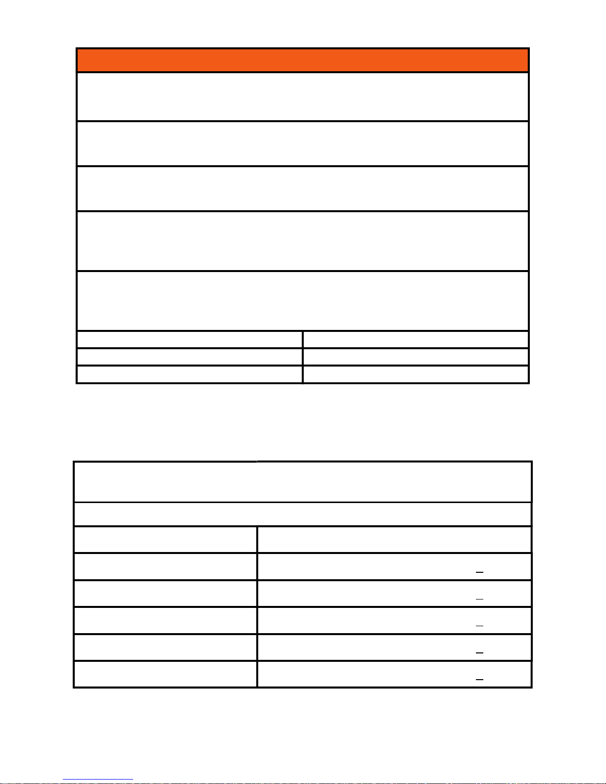
Specification
Wiring Test
Detects missing E or N (>15kΩ)
Detects L-E or L-N swap
Detects Network Supply Live - Earth/Neutral reversal by use of Polarity Test
Pad.
Phase - Neutral voltage measurement accuracy to 1% and displayed on 3
LED’s
< 207 VAC LOW
207- 253 VAC STANDARD
< 253 VAC HIGH
Loop Test
(No trip mode, 3 wire testing, Phase - Neutral - Earth all connected)
Test current <15mA at 253V AC
Range Accuracy
<1Ω Each breakpoint has an accuracy of + 10%
<2Ω Each breakpoint has an accuracy of + 10%
<20Ω Each breakpoint has an accuracy of + 10%
<200Ω Each breakpoint has an accuracy of + 10%
>200Ω Each breakpoint has an accuracy of + 10%
SS004V2
Ordering Information
Item Supplier Code
Socket and See PDL234Plus Part P
Loop testing Kit tester
SOC/PDL234Plus
Socket and See fused test leads SOC/ITLS400
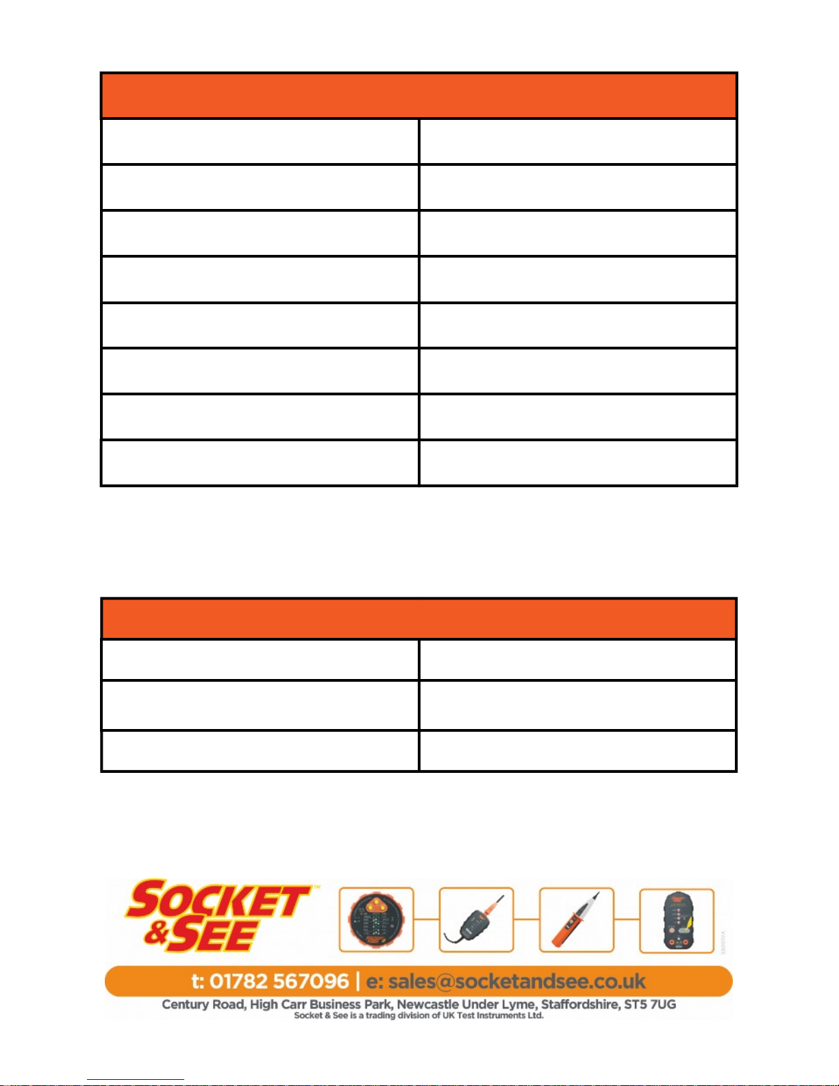
Specification Continued
Overvoltage Category CAT III 300 V
Over Voltage Protection
440V AC No damage complete
recovery
Operating Temperature 0ºC to 40ºC
Operating Humidity 80% @ 31ºC to 50% @ 40ºC
Safety Compliance BS EN 61010-2-030:2010
Probes GS38 Compliant
Dimensions
140mm x 80mm x 31mm
Weight 250g
 Loading...