

Page 1
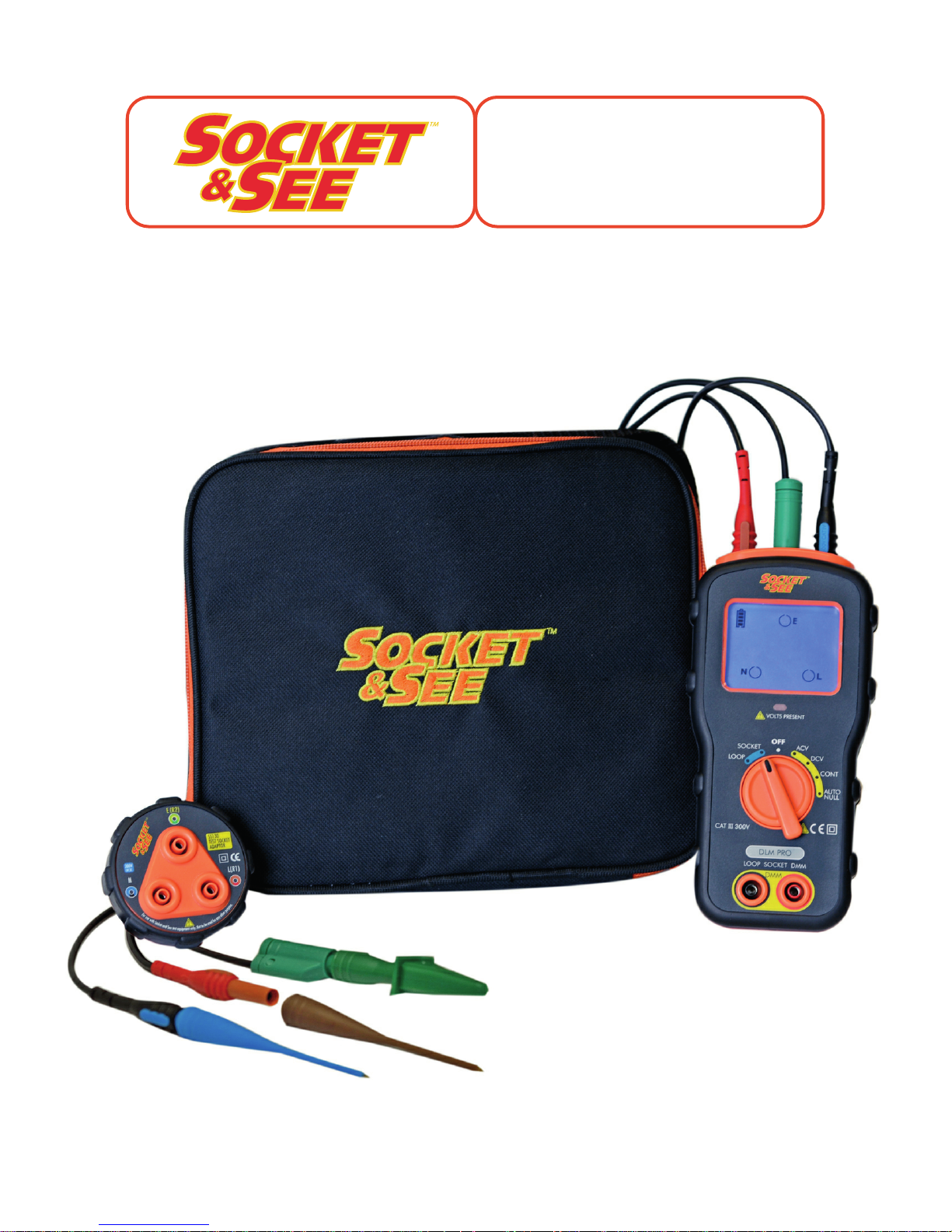
Instruction Manual & Specification
DLM PRO
Combined DMM, Loop and
Socket Tester
Issue1 09/16 SnS037v1
Page 2
1. Safety
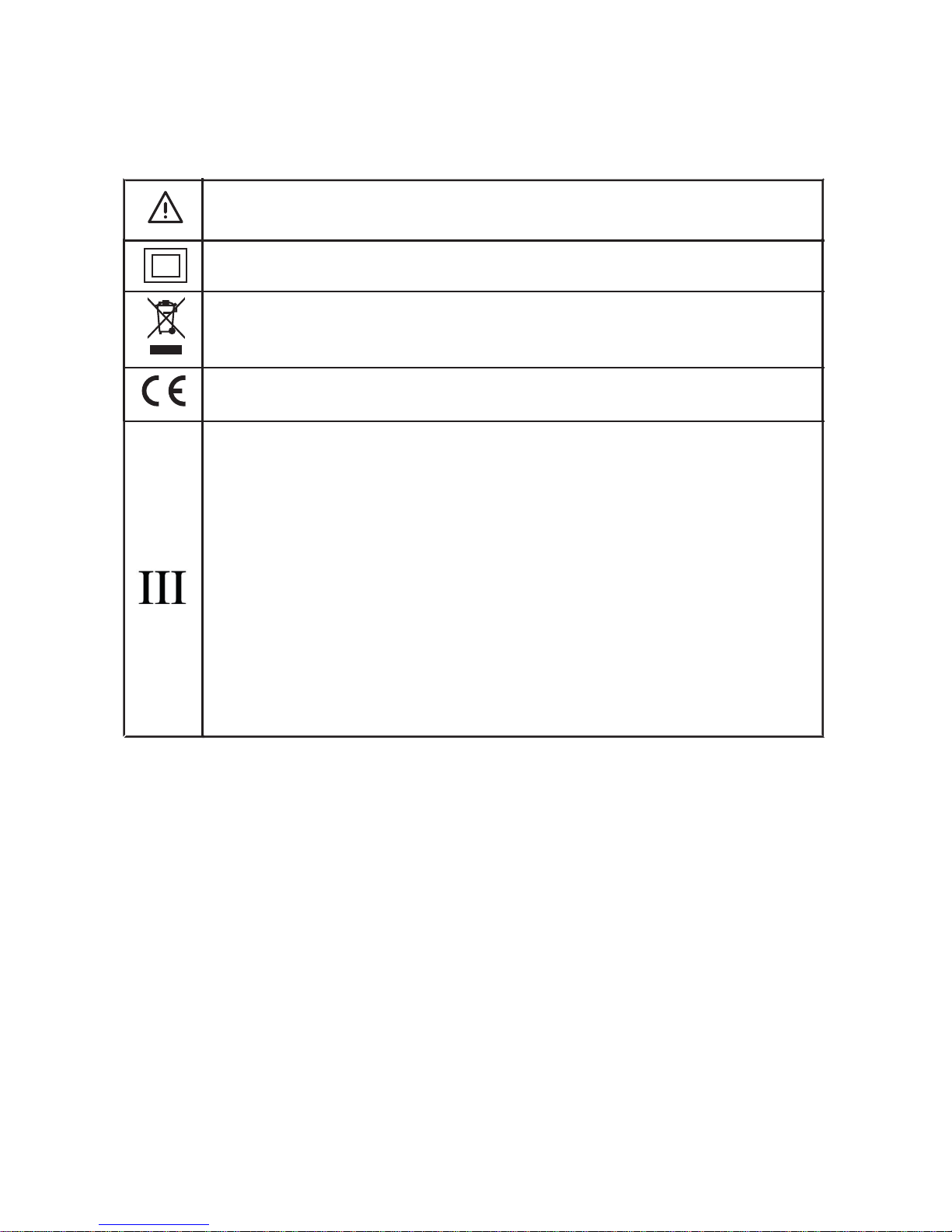
1.1 Equipment Markings
1.2 Operational Safety
The DLM PRO is designed to be used by skilled persons in accordance with safe
methods of work. If the DLM PRO is used in a manner not specified by Socket &
See, the protection provided by it may be impaired.
Inspect the product before using. If any damage is visible; such as cracks in the
casing, damage to any accessories, leads or probes, the unit should not be
used.
This tester has been designed to be used with suitable PPE, including insulated
gloves if required.
The red VOLTS PRESENT LED will illuminate whenever a hazardous voltage is
present at either the top or front terminals. This will illuminate irrespective of the
rotary dial position. Safety related faults will cause the tester to give an audible
and warbling warning tone.
Caution - refer to the instruction manual
Construction is double insulated
Product should be recycled as electronic waste
Conforms to EU standards
300V
Measurement Category III is applicable to test and measuring circuits
connected after the source of the building’s low-voltage MAINS
installation. This part of the installation is expected to have a
minimum of two levels of over-current protective devices between
the transformer and connecting points of the measuring circuit.
Examples of CAT III are measurements on devices installed after the
main fuse or circuit breaker fixed within the building installation. Such
as distribution boards, switches and socket outlets.
CAT
2
Page 3
Do not operate the DLM PRO with the battery cover off as this will compromise
the insulated safety barrier.
To maintain safety, check the tester on a known source or a proving unit such
as the Socket & See SP400 before and after use. To ensure serviceability and to
monitor accuracy of the DLM PRO, a checkbox such as the Socket & See
CB400 can be used.
2. Description
The DLM PRO is a combined AC/DC Voltmeter, Continuity, Socket and Earth
Loop Impedance tester.
2.1 Features
● Volts AC 0-500V, 40-200Hz (Includes automatic ghost voltage suppression)
● Volts DC 0-500V
● Continuity Tester 0-2MΩ
● Socket wiring tester
● Mains voltage check
● No trip Earth Loop Impedance Check
● Clear and simple LCD display
● Auto Null function
● Hazardous voltage present warning LED
● Auto switch off function for battery preservation
● Fabric carrying case
● 4mm test leads and SS130 Socket Adaptor
2.2 Indication
The display backscreen is BLUE during normal operation. To preserve battery life
this is limited to 8 seconds. If a reading changes by more than 3% after this 8
second period, the BLUE backscreen illuminates again.
When a fault condition occurs the display backscreen will illuminate RED.
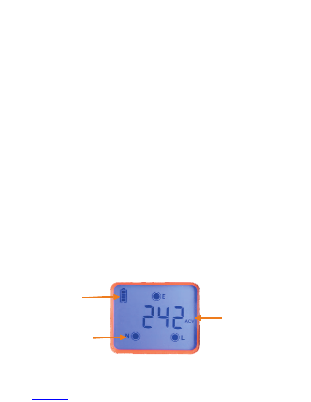
Battery Status.
Solid black dot
indicates wiring is
correct.
Mains Voltage
Indication.
LCD display shown in the SOCKET function.
3
Page 4
4
3. Usage
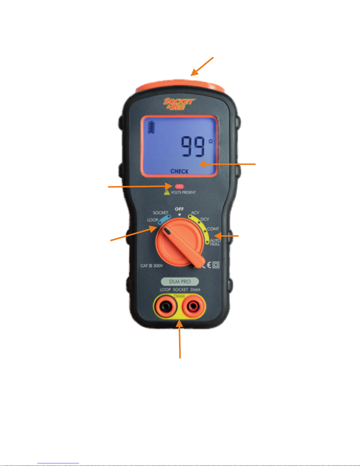
LCD Display
(Shown in LOOP
function)
Volts Present LED.
Illuminated if a
voltage over
50VAC or 70VDC is
detected.
4mm sockets for Live Earth Loop
and Socket testing.
4mm sockets for VAC,
VDC, Continuity, Auto
Null functions.
Socket test/Earth
Loop Impedance
test selection.
Functions operate
from the top three
4mm sockets
DMM Functions
selection. AC Volts,
DC Volts, Continuity,
Auto Null. Functions
operate from the
front two 4mm
sockets.
The DLM PRO is shown in the loop test function
Page 5

5
3.1 Battery Installation
Unit requires 4 x AA batteries.
Ensure that all test leads are removed before installing batteries. Remove the
battery cover on the reverse of the unit. Install the new batteries ensuring
correct polarity as indicated. After installing batteries and before use ensure the
battery cover is correctly fitted, switch on the unit and check for correct
operation.
Dispose of used batteries as per the local authorities guidelines.
3.2 Operation
3.2.1 Digital Multi Meter (DMM) Functions.
Use the two front 4mm sockets when using the DMM functions.
ACV
Turning the rotary dial to the ACV position selects the AC voltage measurement.
The tester will measure from 0-500 Volts RMS, 40-200Hz. If the tester detects a DC
voltage greater than 70V on the terminals an audible warning will be given and
the LCD backscreen will illuminate RED. If a voltage of less than 50VAC is
detected a low impedance is introduced by the tester for automatic ghost
voltage suppression.
DCV
Turning the rotary dial to the DCV position selects the DC voltage measurement.
The tester will measure from 0-500 Volts DC . If the tester detects an AC voltage
greater than 50V on the terminals an audible warning will be given and the LCD
backscreen will illuminate RED.
CONT
Turning the rotary dial to the CONT position selects the continuity measurement.
The tester will measure from 0.1Ω-2MΩ.
Continuity checks must be conducted on dead circuits. If a voltage is detected
on the terminals while switched to continuity an audible warning will be given
and the LCD backscreen will illuminate RED. The DLM PRO is fully protected
against accidental mains connection.
AUTO NULL
Before taking a continuity measurement turn the rotary dial to AUTO NULL and
touch the tips of the test leads firmly together. The tester will then conduct an
auto null as long as the resistance value is less than 5Ω. The tester will bleep
once the auto null has been completed and the NULL icon will show on the
LCD. All of the continuity measurements are then relative as the resistance of
the test leads is taken into account. The NULL value is cleared when the tester is
switched off.
Page 6
3.2.2 Socket and Loop Test Functions.
Use the top three 4mm sockets when using the Socket and Loop Test
functions.
SOCKET
Turing the rotary dial to the SOCKET position selects the socket test and
incoming voltage check. The tester will check the LIVE, NEUTRAL and EARTH
arrangement at the socket to check for correct wiring and open circuits. The
results are diagrammatically shown on the LCD. The LCD will also show the
measured voltage at the socket, (phase to neutral) to the nearest 1V . If the
measured voltage is less than 150V the LCD will display >50V. If all
measurements are correct the LCD backscreen will illuminate BLUE. If any fault
condition is present the backscreen will illuminate RED.
LOOP
Turning the rotary dial to the LOOP position selects the Earth Loop Impedance
test. The tester performs a Live - Neutral and a ‘No Trip’ Live - Earth loop test on
a 13Amp socket.
The tester will monitor the Earth voltage rise, if over 50V is detected the LCD will
display FAIL, The RED backscreen will illuminate and an audible warning will be
given as this is a safety related issue.
The tester will not allow a loop test to be carried out if the socket test function
detects a fault or if the incoming voltage is not between 195V and 253V AC.
Once the Earth Loop Impedance has been measured the DLM PRO
backscreen will illuminate and clear written indication of GOOD, CHECK or FAIL
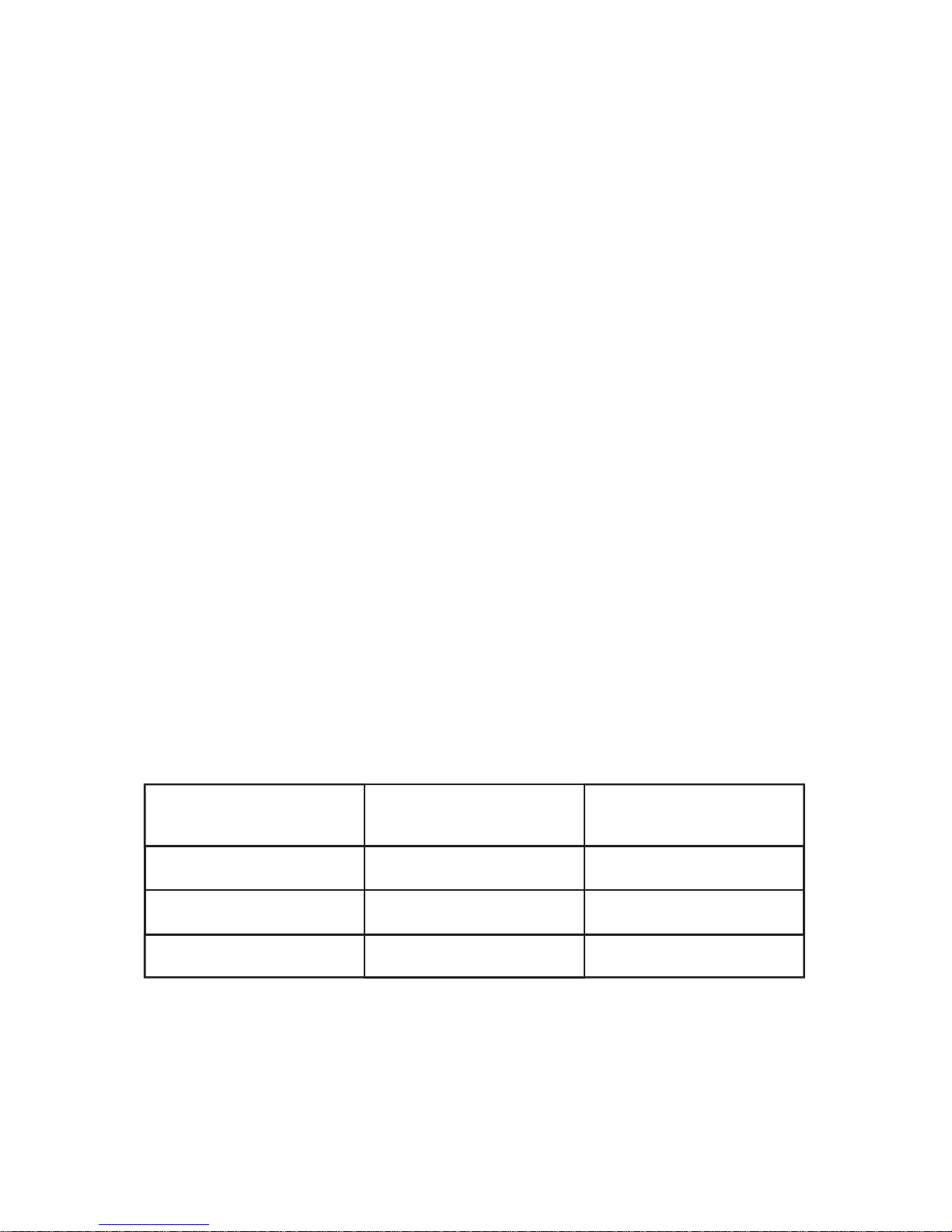
will accompany the numerical value displayed. The values that these written
indications are displayed at are shown in the below table.
If a CHECK or FAIL indication is given this may not be a dangerous condition. It is
dependant upon the numerical value measured on the tester, the earthing
arrangement of the installation and the protective devices being used.
Checks must be carried out to confirm the earthing arrangement to ensure the
earth loop impedance value meets the current wiring regulations.
Indication
Impedance
Value (Ω)
LCD Backscreen
GOOD >1.8 BLUE
CHECK 1.8 - 199 BLUE
FAIL <200 RED
6
Page 7

4. Maintenance and Service
If required, clean with a damp cloth and mild detergent. Do not use abrasives
or solvents.
With the exception of the batteries there are no user serviceable parts.
Contact Socket and See for parts and technical assistance.
Socket & See
Century Road
High Carr Business Park
Newcastle
Staffordshire, UK
ST5 7UG
Tel: +44 (0) 1782 567096
Fax: +44 (0) 1782 567095
Email: [email protected]
Website: www.socketandsee.co.uk
7
Page 8
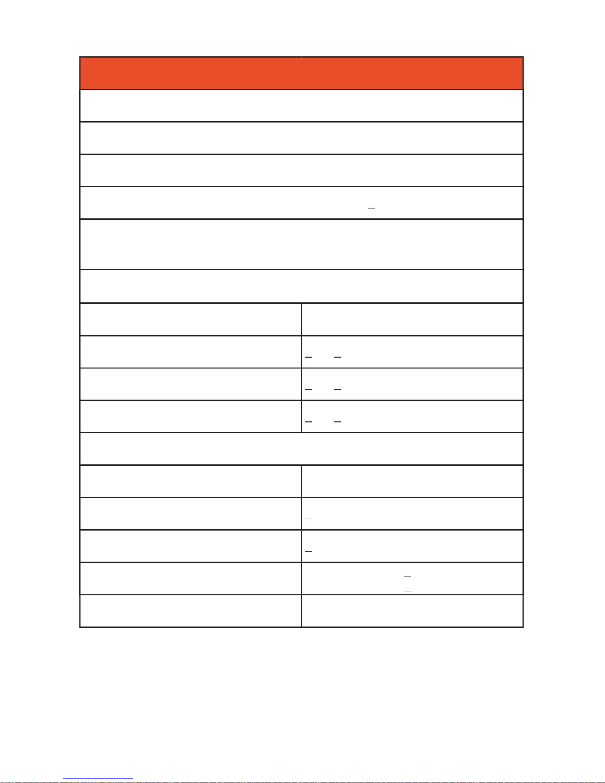
Specification
Wiring Test
Detects missing E or N (>15kΩ)
Detects L-E or L-N swap
Phase - Neutral voltage measurement accurate to +1%
Loop Test
(No trip mode, 3 wire testing, Phase - Neutral - Earth all connected)
Test current <15mA at 253V AC
Auto Range Accuracy
0.00 to 9.99 Ω + 5% + 1 digits
10.00 to 99.9 Ω + 4% + 1 digits
100.00 to 500 Ω + 4% + 1 digits
DMM SETTINGS
Auto Range Accuracy
Volts AC
0-500V, 40-200Hz
+3% +1 digit
Volts DC
0-500V
+1.5% +1 digit
Continuity
0.1Ω-2MΩ
0.1Ω - 1MΩ + 3% +1 digit
1MΩ - 2MΩ + 10% +1 digit
Zero Offset Adjust
(Auto Null)
0-5Ω
8
Page 9
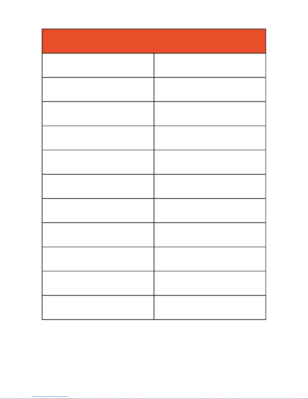
Specification Continued
Power Supply
4 x AA LR6 Batteries
Battery Life
50 Hours
Overvoltage category
CAT III 300V
Operating Temperature
0 - 40ºC
Storage Temperature
-20 to 65ºC
Operating Humidity
0 - 95% @ RH non-condensing
Safety Compliance
BSEN 61010-2-030:2010
EMC Compliance
BSEN 61326-2-2:2013
Probes
GS38 Compliant
Dimensions (mm)
180 x 55 x 85
Weight (g)
430
9
Page 10
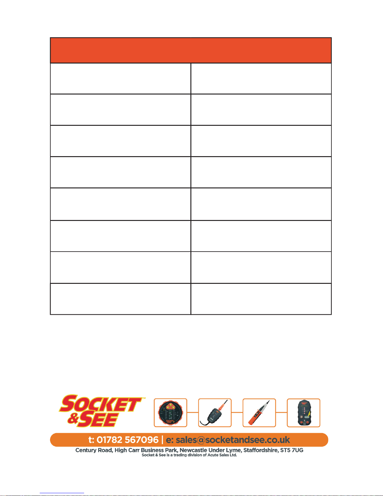
Ordering Information
Item Supplier Code
Socket and See DLM PRO.
Combined DMM, Loop and Socket
Tester
SOC/DLMPRO
Socket and See PDL234Plus.
Part P Loop testing kit
SOC/PDL234Plus
Socket and See SS130.
Socket Adaptor
SOC/SS130
Socket and See SP400.
Proving Unit with Non-Contact
Voltage Check.
SOC/SP400
Socket and See iVolt.
Non-Contact voltage detector.
SOC/iVolt
Socket and See EPF PRO.
Hazardous Voltage and Phase Finder.
SOC/EPFPRO
Socket and See CB400.
Professional non trip check box
SOC/CB400
 Loading...