

Page 1

Gun Scanner Series 2
Socket Gun Scanner (GS) 2X (Xtreme Performance) bar
code laser scanning gun with CompactFlash card and cable
for adding data collection functionality to a variety of
Windows-based mobile computers
User’s Guide
Page 2

8/2005 Document # 6410-00165 H
Copyright Notice
Copyright © 2005 Socket Communications, Inc. All rights reserved.
Socket, the Socket logo and Battery Friendly are registered trademarks of
Socket Communications, Inc. GS 2X and SocketScan are trademarks of
Socket Communications, Inc. All other brand and product names are
trademarks of their respective holders.
The Bar Code Laser Scanning Card includes technology licensed under
United States Patent Nos. 4,543,450, 4,603,320, 4,686,506, and 4,972,470.
Reproduction of the contents of this manual without the permission of
Socket Communications is expressly prohibited. Please be aware that the
products described in this manual may change without notice.
Feel free to contact SOCKET COMMUNICATIONS at:
Socket Communications, Inc.
37400 Central Court
Newark, CA 94560
Other than the above, Socket Communications can assume no responsibility
for anything resulting from the application of information contained in this
manual.
Socket Communications requests that you refrain from any applications of
the product that are not described in this manual. Please refrain from
disassembling the card. Disassembly of this device will void the product
warranty.
You can track new product releases, software updates and technical
bulletins by visiting Socket’s web page at:
www.socketcom.com.
2
Page 3

Table of Contents
1 | INTRODUCTION 5
About the Software 5
Package Contents 6
Scanner Maintenance 6
2 | SCANNING TIPS 7
Aiming 7
Decode Zone 8
LED Definitions 8
Beeper Definitions 9
3 | PREPARING FOR SETUP 10
Register Your Product 10
Uninstall Old Scanning Software 11
Attach the Interface Cable 12
4 | SETUP FOR WINDOWS MOBILE 13
STEP 1: Install the Software 14
STEP 2: Insert the Card into your Device 16
STEP 3: Start SocketScan 17
STEP 4: Scan Data into a Windows Program 18
OPTIONAL: Configure Prefix/Suffixes 20
OPTIONAL: Configure Sounds 21
OPTIONAL: Configure Special Symbologies 22
5 | SETUP FOR WINDOWS 98SE/ME/2000/XP 23
STEP 1: Insert the Installation CD 24
STEP 2: Insert the Card into Your Computer 24
STEP 3: Configure for New Hardware 25
STEP 4: Install SocketScan Software 27
STEP 5: Scan Data into a Windows Program 28
OPTIONAL: Configure Prefix/Suffixes 30
OPTIONAL: Configure Sounds 31
OPTIONAL: Configure Symbologies 32
6 | USER PREFERENCES 33
Hints and Tips on Programming the Scanner 34
User Preferences 35
Set Default Parameters 35
Beeper Tone 35
Beeper Volume 36
Variable Length Scan Line 37
Laser On Time 38
3
Page 4

APPENDICES
A | SPECIFICATIONS 39
B | BAR CODE LABEL SPECIFICATIONS 41
C | DEFAULT PARAMETERS 42
D | SAMPLE BAR CODES 45
E | NUMERIC BAR CODES 46
F | TROUBLESHOOTING 47
G | TECHNICAL SUPPORT 48
H | GLOSSARY 50
Limited Warranty 56
Limited Software Warranty 57
Regulatory Compliance 58
4
Page 5

1 | Introduction
The Socket GS 2X gives you the freedom of
scanning bar codes anytime anywhere with a
variety of Windows-based mobile computers.
The system features the S-2208 scanner, which
combines excellent scanning performance and
advanced ergonomics to provide the best value
in a lightweight laser scanner. The scanner
ensures comfort and ease of use for extended
periods of time.
The Bar Code Laser Scanning Card works in the CompactFlash or PC Card
slot of the following mobile computers:
• Pocket PC 2000/2002/2003/2003SE
• HPC 2000 or pen tablet running Windows Mobile
• Notebook computer running Windows 98SE, Me, 2000 or XP.
Operation in a PC Card slot requires a Type II PC Card adapter, (available
separately, SKU# AC4001-979).
About the Software
The GS 2X include SocketScan™ keyboard emulation software, which
enters scanned data directly into any active Windows program as if it were
manually typed. This is known as a “keyboard wedge.”
Major bar code symbologies are automatically detected,
including Code 39, UPC/EAN, and Code 128. Other
symbologies can be enabled using the S-2208 Advanced
Programming Guide from the Socket website.
You can configure SocketScan to automatically add
prefix/suffixes (e.g., carriage return or tab) to scanned
data, further eliminating the need for manual data
entry. SocketScan also lets you configure a sound to
indicate a good read.
Note: Prefix/suffixes can be enabled either in SocketScan or in the S-2208
laser gun, and the effect is cumulative.
For software updates, or to download the S-2208 Advanced Programming
Guide, please visit:
www.socketcom.com/support/support_bar.asp
CHAPTER 1: INTRODUCTION 5
Page 6

Package Contents
• A Socket Bar Code Laser Scanning Card (CompactFlash), with cable
• A Socket GS 2X
• The SocketScan Installation CD
• The Quick Start Guide software installation, warranty, and copyright
information
• A Type I CompactFlash-to-PC Card adapter (optional)
Note: In case your scanner ever becomes damaged and you want to send it
back to Socket for servicing, KEEP THE ORIGINAL PACKAGING. It is the
approved container for shipping.
Scanner Maintenance
Cleaning the exit window is the only maintenance required. A dirty window
may affect scanning accuracy.
• Do not allow any abrasive material to touch the window
• Remove any dirt particles with a damp cloth or tissue moistened with
ammonia/water. Do not spray water or other cleaning liquids directly
into the window.
6
Page 7

2 | Scanning Tips
Aiming
Do not hold the scanner directly over the bar code, with the laser beam
perpendicular to the bar code. Laser light reflecting directly back into the
scanner from the bar code is known as specular reflection. This specular
reflection can make decoding difficult. You can tilt the scanner up to 55°
forward or back and achieve a successful decode (Figure 2-3). Simple
practice quickly shows what tolerances to work within.
Figure 2-1. Maximum Tilt Angles and Dead Zone
CHAPTER 2: SCANNING TIPS 7
Page 8

Decode Zone
Figure 2-2. S 2208 Decode Zone
LED Definitions
In addition to beeper sequences, the scanner communicates with the user
using a two-color LED display. Table 2-1 defines LED colors that display
during scanning.
Table 2-1. Standard LED Definitions
LED Meaning
Off
Green A bar code was successfully decoded.
Red
8
No power is applied to the scanner, or the
scanner is on and ready to scan.
A data transmission error or scanner
malfunction occurred.
Page 9

Beeper Definitions
The scanner emits different beeper sequences and patterns to indicate
status of the scanner power, symbol decode, decode errors, etc.
Table 2-2. Standard Beeper Definitions
Usage Beeper Sequence Meaning
Standard
Usage
Parameter
Menu
Scanning
Code 39
Buffering
Low/medium/high
beep
Short high beep
4 long low beeps
5 low beeps Conversion or format error.
Lo/hi/lo beep ADF transmit error.
Hi/hi/hi/lo beep RS-232 receive error.
Short high beep
Lo/hi beep
Hi/lo beep
Hi/lo/hi/lo beep
Low/hi/low/hi beep
Hi/lo beep
3 Beeps - long high
beep
Lo/hi/lo beep
Power up.
A bar code symbol was decoded (if decode
beeper is enabled).
A transmission error was detected in a
scanned symbol. The data is ignored. This
occurs if a unit i s not properly configured.
Check option setting.
Correct entry scanned or correct menu
sequence performed.
Input error, incorrect bar code or “Cancel”
scanned, wrong entry, incorrect bar code
programming sequence; remain in program
mode.
Keyboard parameter selected. Enter value
using bar code keypad.
Successful program exit with change in the
parameter setting.
Out of host parameter storage space.
Scan Set Default Parameter in Chapter 6.
New Code 39 data was entered into the
buffer.
Code 39 buffer is full.
The Code 39 buffer was erased or there
was an attempt to clear or transmit an
empty buffer.
Lo/hi beep A successful transmission of buffered data
CHAPTER 2: SCANNING TIPS 9
Page 10

3 | Preparing for Setup
This chapter explains preliminary steps that you should complete prior
to installing the GS 2E. After completing the steps in this chapter,
proceed to the appropriate chapter for the setup instructions for your
specific Windows version.
This chapter covers the following:
• Registering your product
• Uninstalling old scanning software
• Attaching the interface cable
Register Your Product
Socket highly recommends that all users register their Socket products.
Registered users receive priority for technical support. Register online at:
www.socketcom.com/prodreg
Product registration is not required to ensure your warranty rights.
10
Page 11

Uninstall Old Scanning Software
Delete any bar code scanning software you may already have installed on
your mobile computer.
Windows Mobile:
For Windows Mobile devices, you have two options for uninstalling
scanning software.
OPTION 1: Uninstall Directly from Device
1. Make sure the bar code scanning software is closed, and remove the Bar
Code Laser Scanning Card from your mobile computer.
2. Tap Start | Settings. Tap on the System tab or Control Panel.
3. Tap on the Remove Programs icon.
4. Select the bar code scanning software, then tap Remove.
5. Tap Yes to confirm removal of the program.
OPTION 2 Uninstall via ActiveSync
1. Make sure the bar code scanning software is closed, and remove the Bar
Code Laser Scanning Card from your mobile computer.
2. Use ActiveSync and a serial/Ethernet/USB cable or cradle to make an
active connection between your Pocket PC and a host PC.
3. On the host PC, open Microsoft ActiveSync.
4. Click Tools | Add/Remove Programs.
5. Select the bar code scanning software and click Remove.
6. In the confirmation screen, click OK.
7. The next dialog will ask if you want to remove the software from your
host PC as well.
• Click NO to keep a copy of the software on the host PC that can later
be re-installed onto a Pocket PC.
• Click YES to remove the software from the host PC.
Windows 98SE/Me/2000/XP:
1. Go to Start | Settings | Control Panel | Add or Remove Programs
2. Select the bar code scanning program and click Remove .
3. Follow the instructions on your screen until the program has been
removed.
CHAPTER 3: PREPARING FOR SETUP 11
Page 12

Attach the Interface Cable
1. Plug the interface cable modular connector into the cable interface
port on the bottom of the scanner handle.
2. Gently tug the cable to ensure the connector is properly secured.
3. Connect the other end of the interface cable to the host (see the
specific host chapter for information on host connections).
12
Page 13

4 | Setup for Windows Mobile
This chapter shows how to install, configure, and use the Socket GS 2X on
any of the following mobile computers based on Windows Mobile:
• Pocket PC 2000/2002/2003/2003SE
• HPC 2000 or pen tablet based on Windows Mobile
This chapter shows Pocket PC 2002 screens. Other Windows Mobile
devices will have functionally equivalent screens except where otherwise
noted.
Setup Summary
STEP 1: Install the software.
STEP 2: Insert the Card into Your Device.
STEP 3: Start SocketScan.
STEP 4: Scan data into a Windows program.
OPTIONAL:
• Configure prefix/suffixes.
• Configure sounds.
• Manually configure symbologies or extensions.
CHAPTER 4: SETUP FOR WINDOWS MOBILE 13
Page 14

STEP 1: Install the Software
Follow these steps for software installation BEFORE inserting the Bar
Code Laser Scanning Card into your mobile computer.
1. Use ActiveSync and a serial/Ethernet/USB cable or cradle to make an
active connection between the mobile computer and a host PC.
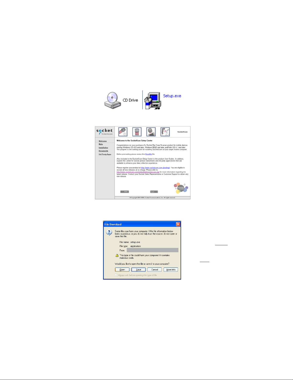
2. Insert the SocketScan Installation CD into your CD-ROM dr ive.
3. Use My Computer or Windows Explorer to access your CD-ROM drive.
In the CD, click on SETUP.EXE.
4. Follow the instructions on the host PC screen to install the software for
Windows CE.
• Read the information in the welcome screen and click next.
• In the Main Page, click Install Software.
• In the Installation screen, click Windows CE.
14
Page 15

5. In the File Download screen, select the option that lets you OPEN
(or run) the file from its current location.
IMPORTANT!
YOU MUST
OPEN
THE FILE!
NOT SAVE!
DO
Note: If the File Download screen reports that the file may be harmful,
disregard the warning and open the file.
6. Follow the instructions that appear on your screen until setup is done.
7. Disconnect the mobile computer from the host PC.
8. Soft reset the mobile computer by pressing the reset button.
Important!
Be sure to soft reset your mobile computer after software installation!
Press the reset button, which may be located on the back of your mobile
computer!
CHAPTER 4: SETUP FOR WINDOWS MOBILE 15
Page 16

STEP 2: Insert the Card into your Device
1. If you have not installed the interface cable yet, plug it in now. Refer to
Chapter 2, “Preparing for Setup” for instructions.
2. Insert the Socket Bar Code Laser Scanning Card into the appropriate
slot of your mobile computer.
To use the Bar Code Laser Scanning Card in a PC Card slot, first insert
into a CompactFlash-to-PC Card adapter.
16
Page 17

STEP 3: Start SocketScan
1. Pocket PC: Go to Start | Programs | SocketScan.
Tap on
SocketScan.
HPC 2000: Tap on the SocketScan icon on your desktop.
2. Whenever SocketScan is running, either of two icons may appear in the
menu bar (visible from the Today screen for Pocket PCs).
Scanning Card
detected
No scanning
card detected
3. Make sure the “Scanning Card detected” icon appears. If the “No
scanning card detected” icon appears, you may have an improperly
inserted card. Remove and reinsert the card, pushing it in all the way.
CHAPTER 4: SETUP FOR WINDOWS MOBILE 17
Page 18

STEP 4: Scan Data into a Windows Program
1. Make sure SocketScan is open.
2. Start the Windows application that
you want to receive the data (e.g.,
Excel, Notepad, etc.).
Make sure a new document or
spreadsheet is open.
For information about bar code
scanning applications, please vist:
www.socketcom.com/solutions
3. Make sure all cable connections are secure.
4. Now you are ready to scan. Aim the scanner at the bar code and press
the trigger.
Make sure the scan line crosses every bar and space of the symbol.
RIGHT WRONG
Important! Do not look directly into the laser beam or point it at a
person!
18
Page 19

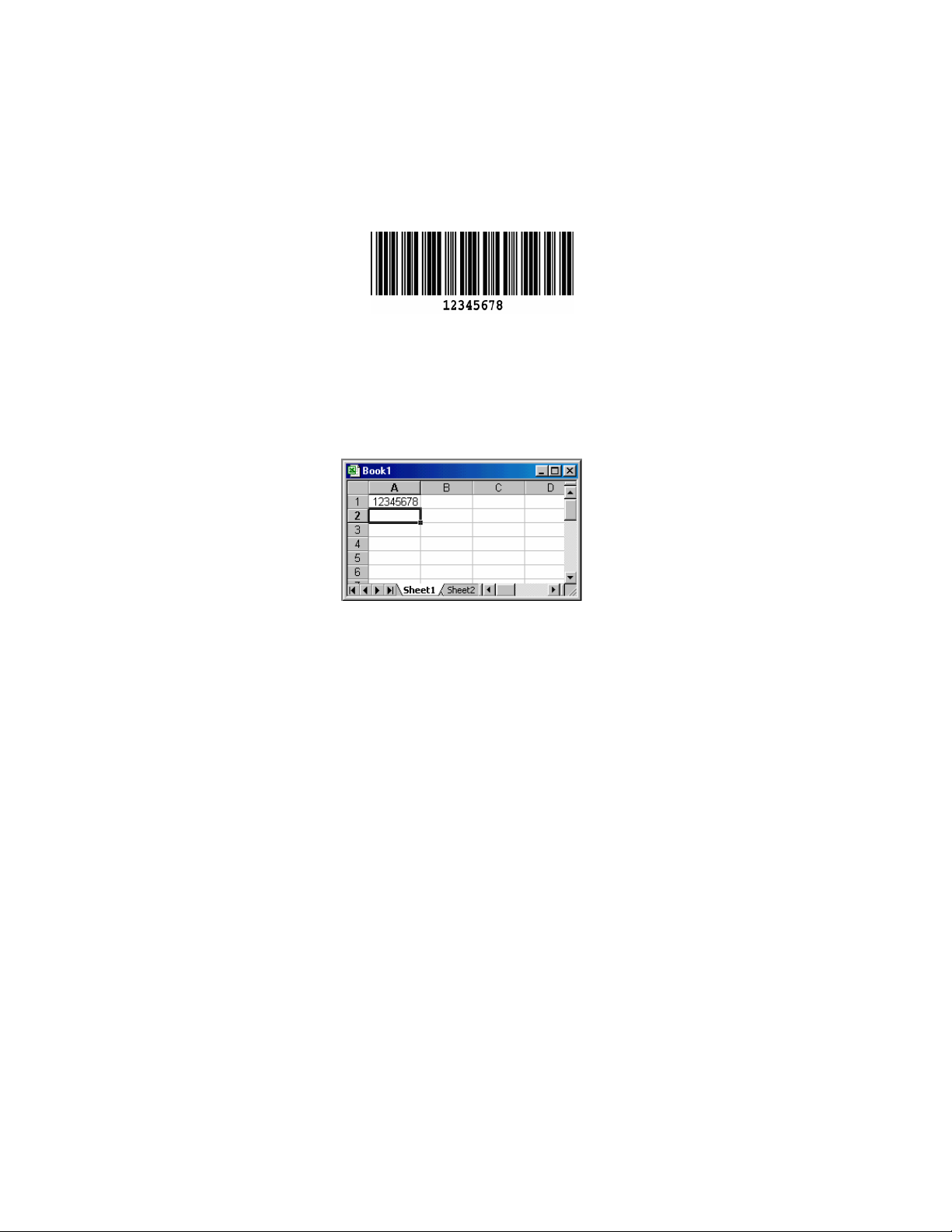
For example, try this Code 39 bar code:
Upon successful decode, the scanner beeps and the LED turns green.
(For more information on beeper and LED definitions, refer to Table
2-1 and Table 2-2.)
5. After a successful scan, data should appear in your document.
For example, after you scan the code above into a Pocket Excel
spreadsheet, data should appear in the first cell. The default Carriage
Return suffix will cause the next cell to be highlighted and ready for
data input.
CHAPTER 4: SETUP FOR WINDOWS MOBILE 19
Page 20

OPTIONAL: Configure Prefix/Suffixes
The SocketScan Prefix/Suffix applet lets you specify prefix and/or suffix
characters to be added automatically to the data you scan. This helps to
further eliminate manual data entry.
1. Tap on the SocketScan icon in the menu bar
(visible in the Today screen for Pocket PCs).
Note: You can configure prefix/suffixes if the “no scanning card
detected” icon appears.
2. In the pop-up menu, select Prefix/Suffix...
to launch the applet
3. In the screen that appears, enter the characters you want to be appended
to each scan (128 character maximum). Tap ok.
Note: Only printable
ASCII characters can be
used as prefixes or
suffixes.
Note: A prefix or suffix can also be programmed into the S-2208, and the
effect is cumulative. SocketScan should be used to configure simple actions
such as a Carriage Return. For more complex prefix/suffixes or Advanced
Data Formatting, use the S-2208 Advanced Programming Guide to
program these functions directly into the gun. In this case, the default
Carriage Return suffix in SocketScan should be removed.
Download the S-2208 Advanced Programming Guide from:
www.socketcom.com/support/support_bar.asp
20
Page 21

OPTIONAL: Configure Sounds
The SocketScan Sounds applet lets you choose any WAV sound file to be
played by the host device to indicate a successful scan.
Note: Since the S-2208 also beeps this feature may not be needed.
WARNING!
DO NOT ASSIGN A .WAV FILE ON A POCKET PC 2003/2003SE, OR
THE SOFTWARE MAY LOCK UP!
1. Tap on the SocketScan icon in the menu bar to
launch the applet (visible in the Today screen for
Pocket PCs). In the pop-up menu, select Sounds...
2. In the screen that appears, select a sound for indicating good scans. Tap
ok.
Browse box
If you want to play a .WAV file, after selecting Play .wav file, you can
search through files by tapping the browse box. In the Open screen, tap
on the file you want:
Note: For Pocket
PCs, you can only
select a WAV file
from the My
Documents folder.
If needed, copy the
file you need to this
folder.
CHAPTER 4: SETUP FOR WINDOWS MOBILE 21
Page 22

OPTIONAL: Configure Special Symbologies
You can manually configure the scanner for specific user preferences and
scanning options. Refer to Chapter 6, “User Preferences” for instructions.
Refer to Appendix C, “Default Parameters,” to see parameter numbers and
default settings of each symbology. Also please refer to the S-2208
Advanced Programming Guide, available online in Adobe Acrobat PDF
format at:
www.socketcom.com/support/support_bar.asp
22
Page 23

5 | Setup for Windows
98SE/Me/2000/XP
This chapter explains how to install the GS 2E on a notebook or pen tablet
computer running any of the following Windows versions:
• Windows 98 Second Edition
• Windows Me, 2000 or XP
This chapter features screen images from Windows 98SE. Other Windows
versions will have functionally equivalent screens except where otherwise
noted.
Note: The GS 2E does NOT work with Windows NT.
Setup Summary
STEP 1: Insert the installation CD.
STEP 2: Insert the card.
STEP 3: Configure Windows for new hardware.
STEP 4: Install SocketScan software.
STEP 5: Scan data into a Windows program.
OPTIONAL: Configure prefix/suffixes
OPTIONAL: Configure sounds.
OPTIONAL: Configure SocketScan for specific symbologies or extensions.
CHAPTER 5: SETUP FOR WINDOWS 98SE/ME/2000/XP 23
Page 24

STEP 1: Insert the Installation CD
Insert the SocketScan Installation CD into your CD-ROM drive.
STEP 2: Insert the Card into Your Computer
1. If you have not installed the interface cable yet, plug it into the scanning
gun. Refer to Chapter 2, “Preparing for Setup,” for instructions.
Windows 2000/XP: Make sure you are logged on as the Administrator or
2.
on an account that has Administrative rights.
3. Insert the Bar Code Laser Scanning Card into a CompactFlash-to-PC
Card adapter, then plug the combined unit into your computer’s PC
Card slot.
Windows 2000/XP: After you insert the card, a screen may appear
4.
reporting Digital Signature Not Found. Click Yes.
24
Page 25

STEP 3: Configure for New Hardware
1. Make sure the installation CD is still inside your computer.
2. The first time you insert the Bar Code Laser Scanning Card, a new
hardware or device driver wizard will appear. Complete the wizard by
following the appropriate instructions for your Windows version:
Windows XP
• Select Install from a list or specific location. Click Next>.
• Select Include the location in the search and browse to the CD drive. Click Next>.
Note: If a screen reports that the product has not passed Windows logo
testing, ignore and click Continue Anyway.
• Follow the remaining instructions until installation is complete.
Windows 2000
• In the second screen, select Search for a suitable driver for my device.
• Check Specify a location and browse to your CD drive. Click OK.
• Follow the remaining screens until the drivers are installed.
CHAPTER 5: SETUP FOR WINDOWS 98SE/ME/2000/XP 25
Page 26
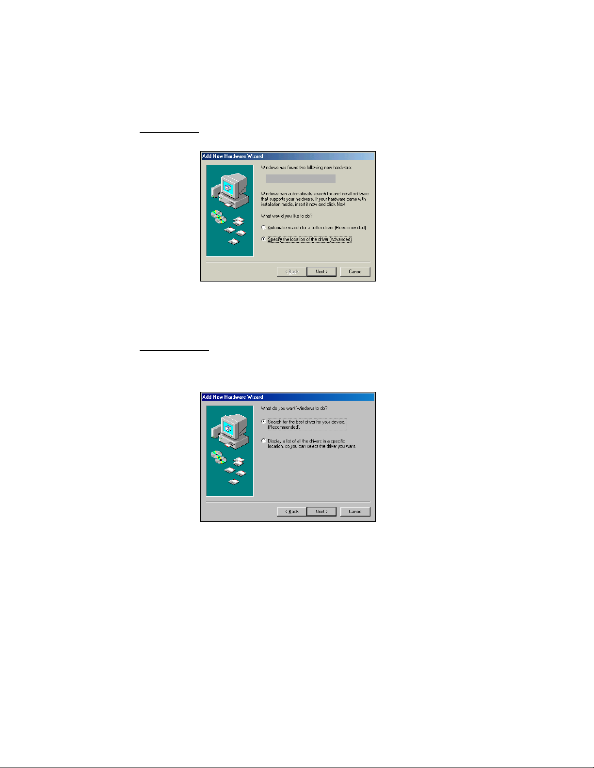
Windows Me
• Select Specify the location of the driver.
WARNING!
FOR WINDOWS Me,
DO NOT SELECT
Automatic search for
a new driver!
• In the next screen, select Search for the best driver for your device, and
check Removable Media. Click Next>.
• Follow the remaining screens until installation is complete.
Windows 98SE
• The first screen will introduce the wizard. Click Next>.
• In the next screen, select Search for the best driver for your device.
Click Next>.
• In the next screen, check CD-ROM drive. Click Next>.
• Follow the remaining screens until the drivers are installed.
26
Page 27
STEP 4: Install SocketScan Software
1. Make sure the SocketScan Installation CD is still inside your computer.
2. Use My Computer or Windows Explorer to access your CD-ROM drive.
In the CD, click on SETUP.EXE.
3. Follow the instructions on the host PC screen to install the software for
your Windows version.
4. In the File Download screen, select the option that lets you OPEN (or
run) the file from its current location.
IMPORTANT!
YOU MUST
THE FILE!
NOT SAVE!
DO
Note: If the File Download screen reports that the file may be harmful,
disregard the warning and open the file.
5. The Setup program will begin. Follow the instructions that appear on
your screen until installation is complete.
6. Restart your computer.
CHAPTER 5: SETUP FOR WINDOWS 98SE/ME/2000/XP 27
OPEN
Page 28

STEP 5: Scan Data into a Windows Program
Follow these steps to use the GS 2X to scan data into a Windows program.
For information about bar code scanning applications (available separately),
www.socketcom.com/solutions
visit:
1. Start SocketScan. Click Start | Programs | SocketScan.
2. Start the Windows application you want to receive the data, such as
Notepad, Word or Excel. Make sure a document or spreadsheet is open.
3. Now you are ready to scan. Aim the scanner at the bar code and press
the trigger.
Make sure the scan line crosses every bar and space of the symbol.
RIGHT WRONG
Important! Do not look directly into the laser beam or point it at a
person!
28
Page 29
For example, try this Code 39 bar code:
Upon successful decode, the scanner beeps and the LED turns green.
(For more information on beeper and LED definitions, refer to Table
2-1 and Table 2-2.)
4. After a successful scan, data should appear in your document. If you
scan the code above into an Excel spreadsheet, data should appear in the
first cell:
CHAPTER 5: SETUP FOR WINDOWS 98SE/ME/2000/XP 29
Page 30

OPTIONAL: Configure Prefix/Suffixes
The SocketScan applet lets you specify prefix and suffix characters or
functions to be added automatically to the data that you scan.
1. Right-click on the SocketScan icon
your screen. In the pop-up menu, select Settings…
in the task bar at the bottom of
2. Start the applet. In SocketScan Settings, click on the Prefix/Suffix tab.
3. In the Prefix and Suffix fields, enter the characters you want to be
appended to each scan (128 character maximum). Click OK.
Note: Only printable
ASCII characters can be
used as prefixes or
suffixes.
Note: A prefix or suffix can also be programmed into the S-2208, and the
effect is cumulative. SocketScan should be used to configure simple actions
such as a Carriage Return. For more complex prefix/suffixes or Advanced
Data Formatting, use the S-2208 Advanced Programming Guide to
program these functions directly into the gun. In this case, the default
Carriage Return suffix in SocketScan should be removed.
Download the S-2208 Advanced Programming Guide from:
www.socketcom.com/support/support_bar.asp
30
Page 31
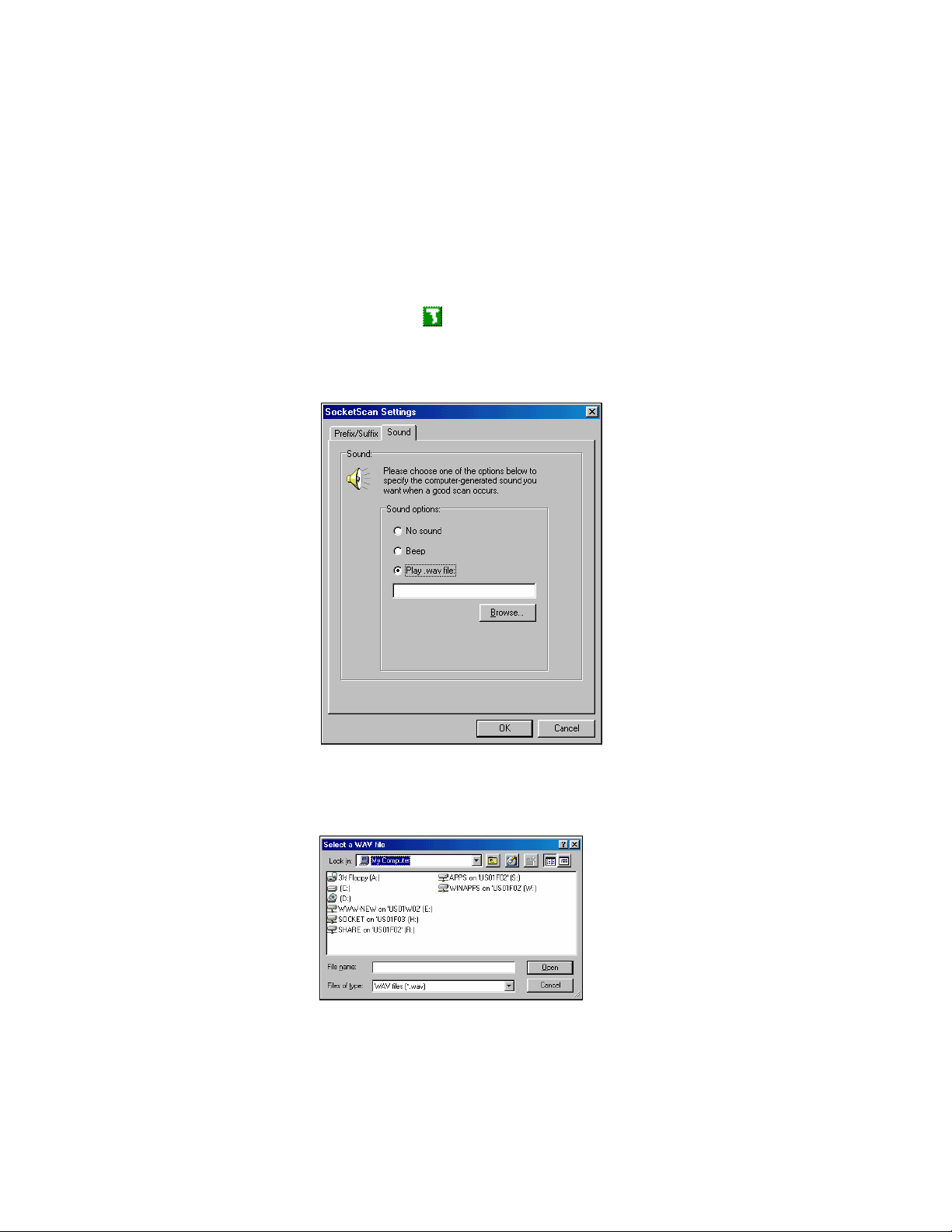
OPTIONAL: Configure Sounds
The SocketScan applet lets you choose a WAV sound file to be played by
the host device to indicate a successful scan.
Note: Since the S-2208 also beeps this feature may not be needed.
1. Tap on the SocketScan icon
select Settings. Click on the Sound tab.
2. Select a sound for indicating successful scans, then click OK.
in the task bar. In the pop-up menu,
To you want to play a .WAV file, after selecting Play .wav file, you can
search through files by tapping the Browse button. In the Select a WAV
file screen, select the file you want, then click on the Open button:
CHAPTER 5: SETUP FOR WINDOWS 98SE/ME/2000/XP 31
Page 32

OPTIONAL: Configure Symbologies
You can manually configure the scanner for specific user preferences and
scanning options. Refer to Chapter 6, “User Preferences” for instructions.
Refer to Appendix C, “Default Parameters,” to see parameter numbers and
default settings of each symbology. Also please refer to the S-2208
Advanced Programming Guide, available online in Adobe Acrobat PDF
format at:
www.socketcom.com/support/support_bar.asp
32
Page 33

6 | User Preferences
This chapter provides bar codes for programming the Socket S 2208
scanner for the following optional user preferences:
• Beeper tone
• Beeper volume
• Variable length scan line
• Laser on time
Your scanner is shipped with the settings shown below (al s o see
Appendix C, “Default Parameters,” for a complete list with all
parameters). If the default values suit your requirements, programming
may not be needed.
Table 6-1. Default User Preferences
Parameter (User Preference) Default
Set Default Parameters All Defaults
Beeper Tone Medium
Beeper Volume High
Variable Length Scan Line Full Length
Laser On Time 3.0 Sec
IMPORTANT!
The S-2208 is pre-programmed to operate only with the Socket Bar
Code Laser Scanning Card and cable. Changing any host or
communication protocol parameters will cause the scanner to be
inoperative.
To prevent accidental modifications to the S-2208 default parameters,
all host and communication programming bar codes have been removed
from both this User’s Guide and the S-2208 Advanced Programming
Guide available on Socket’s website.
CHAPTER 6: USER PREFERENCES 33
Page 34

Hints and Tips on Programming the Scanner
• Scanning Sequence
In most cases you need only scan one bar code to set a specific
parameter value. For example, to set the beeper tone to high, simply
scan the High Frequency (beeper tone) bar code listed under Beeper
Tone. The scanner issues a short high beep and the LED turns green,
signifying a successful parameter entry.
• Preservation of Settings
The settings are stored in non-volatile memory and are preserved
even when the scanner is powered down.
• Errors While Scanning
Unless otherwise specified, if you make an error during a scanning
sequence, just re-scan the correct parameter.
• Resetting Defaults
To return all features to their default values, simply scan the Set All
Defaults bar code.
WARNING!
DO NOT SCAN THE BAR CODES IN THIS
CHAPTER WITH ANY SOCKET SCANNER
PRODUCT OTHER THAN THE S-2208 GUN.
34
Page 35

User Preferences
Set Default Parameters
Return all parameters to the default values listed in Appendix C.
Set All Defaults
Beeper Tone
Set the decode beep frequency (tone) to low, medium or high.
*Medium Frequency
High Frequency
WARNING!
DO NOT SCAN THE BAR CODES IN THIS CHAPTER WITH ANY
SOCKET SCANNER PRODUCT OTHER THAN THE S-2208 GUN.
CHAPTER 6: USER PREFERENCES 35
Page 36

Beeper Volume
Set the beeper volume to low, medium or high.
Low Volume
(change bar code in PDF)
Medium Volume
(change bar code in PDF)
*High Volume
WARNING!
DO NOT SCAN THE BAR CODES IN THIS CHAPTER WITH ANY
SOCKET SCANNER PRODUCT OTHER THAN THE S-2208 GUN.
36
Page 37

Variable Length Scan Line
The scanner can be activated to produce a scan line of either of two lengths
to read bar codes that are closely spaced together such as those found in a
pick list or a bar code menu.
Short Length Scan Line
Full Length Scan Line
WARNING!
DO NOT SCAN THE BAR CODES IN THIS CHAPTER
WITH ANY SOCKET SCANNER PRODUCT OTHER
THAN THE S-2208 GUN.
CHAPTER 6: USER PREFERENCES 37
Page 38

Laser On Time
This parameter sets the maximum time that decode processing continues
during a scan attempt. It is programmable in 0.1 second increments from
0.5 to 9.9 seconds. The default Laser On Time is 3.0 seconds.
Note: Under normal circumstances, 3 seconds is more than enough time to
scan a bar code. Increasing the Laser On Time will decrease the battery life
of the host device.
To set a Laser On Time:
1. Scan the Laser On Time bar code below.
2. Go to Appendix E, “Numeric Bar Codes,” and scan the two numeric bar
codes that correspond to the desired on time. Single digit numbers must
have a leading zero.
For example, to set an On Time of 0.5 seconds, scan the bar code below,
then scan the “0” and “5” bar codes.
3. If you make an error, or wish to change your selection, scan Cancel in
Appendix E.
Laser On Time
WARNING!
DO NOT SCAN THE BAR CODES IN THIS CHAPTER WITH ANY
SOCKET SCANNER PRODUCT OTHER THAN THE S-2208 GUN.
38 CHAPTER 6: USER PREFERENCES
Page 39

Appendix A Specifications
Bar Code Laser Scanning Card Specifications
Physical Characteristics:
Card Dimensions: 36.4 x 42.8 x 3.3 mm
Cable Length: 2 m extended
Operating System Support:
Windows Mobile for Pocket PC 2000/2002/2003/2003SE and HPC 2000
Windows 98SE, Me, 2000, XP
Interface Standards:
CompactFlash Type I
With adapter: PC Card Type II, JEIDA 4.1
Software Included: SocketScan CD
Warranty: Three years
Certification/Compliance:
FCC: Part 15, Class B
CE: EN55024:1998, C-TICK s.182
CompactFlash Spec. 2.0
S-2208 Scanner Specifications
Item Description
Power Requirements 3.3 VDC + / - 10% @ approximately 185mA (nominal)
Stand-By Current 10mA (typical)
UPC/EAN, UPC/EAN with supplementals, UCC/EAN
128, Code 39, Code 39 Full ASCII, Code 39 Trioptic,
Decode Capability
Beeper Operation User-selectable: Enable, Disable
Beeper Volume User-selectable: three levels
Beeper Tone User-selectable: three tones
Scan Repetition Rate 100 ± 5 scans/second
Codabar (NW7), Interleaved 2 of 5, Discrete 2 of 5,
Code 128, Code 93, MSI, Code 11, UCC/EAN RSS,
Code 32, Coupon Code, Bookland EAN, Chinese 2 of
5, 1ATA, and JAN 8 & 13.
APPENDIX A: SPECIFICATIONS | 39
Page 40

Item Description
Yaw Tolerance ± 10° from nominal
Pitch Tolerance ± 65° from nominal
Roll Tolerance
Print Contrast Minimum
Ambient Light Immunity
Indoor:
Outdoor:
Durability Repeated 5 ft (1.5 m) drops to concrete
Operating Temperature 32° to 104° F (0° to 40° C)
Storage Temperature -40° to 140° F (-40° to 60° C)
Humidity 5% to 95% (non-condensing)
Weight (without cable) 5.15 oz. (146 g)
± 60° from nominal
25% minimum reflectance differential, measured at
650 nm.
450 Ft Candles (4,842 Lux) (indoor)
10,000 Ft Candles (107,600 Lux) (outdoor)
Dimensions:
Height
Width
Depth
Laser 650nm laser diode
Laser Classifications IEC 825-1 Class 2
ESD
Minimum Element Width 5 mil (0.127 mm)
Interfaces Supported Socket CompactFlash (CF) Card only
Electrical Safety
Input Transient Protection IEC 1000-4-(2,3,4,5,6,11)
EMI
6.2 in. (15.2 cm)
2.48in. (6.3 cm)
3.34 in. (8.4 cm)
15 kV area discharge
8 kV contact discharge
Certified Pending to UL1950, CSA C22.2 No.950.
EN60950/IC950
FCC Part 15 Class A, ICES-003 Class A European
Union EMC Directive, Australian SMA
40 | APPENDIX A: SPECIFICATIONS
Page 41

Appendix B Bar Code Label
Specifications
All bar code symbols/labels should satisfy the appropriate AIM Uniform
Symbology Specification.
Background Substrate:
The bar code symbol should be printed on material (media) that is reflective
and has a matte (not glossy) finish. A background diffuse reflectance of at
least 70% to 80% is desirable for optimum contrast. Retro-reflective media
should be used to obtain decode distances greater than 36 inches.
Ink Color and Type:
The inked bars should not exceed 25% reflectance at the wavelength that is
being used for reading, whether printed with black ink or colored ink. The
reflectance value should not vary more than 5% within the same character.
Voids and Specks:
The code should be printed clearly, free of voids, specks, blemishes and
lines that could “fool” the scanner. Specks or blemishes in the white
spaces, or false or missing bar sections could be interpreted by the reading
equipment as part of the code. Generally, the width of such flaws is more
serious than the height. Code symbols/ labels should be rejected if these
defects are present.
Definition:
The bars in the bar code symbol should be well defined. Their edges
should not be rough or fuzzy, so that the bars and spaces have the proper
widths intended for the bar code symbology used.
Contrast:
Background reflectance (that of the substrate on which the codes are
printed) should always provide a good contrast relative to the ink
reflectance (that of the code bars). The difference between the two should
be at least 37.5% at the wavelength used for reading.
Tolerance:
The ratio of the widths of bars and spaces in a bar code symbol must
conform to the appropriate AIM bar code specifications and can cause
problems if not correct throughout the bar code. Problems can occur when
bar edges are smeared or rough, or when they exhibit voids.
APPENDIX B: BAR CODE LABEL SPECIFICATIONS | 41
Page 42

Appendix C Default Parameters
Table C-1. Standard Default Parameters Table
Parameter Type/
Symbology
Parameter Default
User Preferences
UPC/EAN
Set Default Parameter All Defaults
Beeper Tone Medium
Beeper Volume High
Laser On Time 3.0 Sec
Beep After Good Decode Enable
UPC-A Enable
UPC-E Enable
UPC-E1 Disable
EAN-8 Enable
EAN-13 Enable
Bookland EAN Disable
Decode UPC/EAN Supplementals (2 and 5 digits) Ignore
Decode UPC/EAN Supplemental Redundancy 7
Transmit UPC-A Check Digit Enable
Transmit UPC-E Check Digit Enable
Transmit UPC-E1 Check Digit Enable
UPC-A Preamble System Character
UPC-E Preamble System Character
UPC-E1 Preamble System Character
Convert UPC-E to A Disable
Convert UPC-E1 to A Disable
EAN-8 Zero Extend Disable
UPC/EAN Security Levels 0
UCC Coupon Extended Code Disable
42 | APPENDIX C: DEFAULT PARAMETERS
Page 43
Parameter Type/
Symbology
Parameter Default
Code 128
Code 39
Code 93
Code 11
Code 128 Enable
UCC/EAN-128 Enable
ISBT 128 (non-concatenated) Enable
Code 39 Enable
Trioptic Code 39 Disable
Convert Code 39 to Code 32 (Italian Farmer Code) Disable
Code 32 Prefix Disable
Set Length(s) for Code 39 2 to 55
Code 39 Check Digit Verification Disable
Transmit Code 39 Check Digit Disable
Code 39 Full ASCII Conversion Disable
Buffer Code 39 Disable
Code 93 Disable
Set Length(s) for Code 93 4 to 55
Code 11 Disable
Set Lengths for Code 11 4 to 55
Code 11 Check Digit Verification 0
Interleaved 2 of 5
(ITF)
Discrete 2 of 5 (DTF)
Codabar (NW – 7)
Transmit Code 11 Check Digit Disable
Interleaved 2 of 5 (ITF) Enable
Set Length(s) for I 2 of 5 2 to 55
I 2 of 5 Check Digit Verification Disable
Transmit I 2 of 5 Check Digit Disable
Convert I 2 of 5 to EAN 13 Disable
Discrete 2 of 5 Disable
Set Length(s) for D 2 of 5 12
Codabar Disable
Set Lengths for Codabar 5 to 55
CLSI Editing Disable
APPENDIX C: DEFAULT PARAMETERS | 43
Page 44

Parameter Type/
Symbology
MSI
Parameter Default
NOTIS Editing Disable Codabar (NW – 7)
Demote RSS Disable
MSI Disable
Set Length(s) for MSI 1 to 55
MSI Check Digits One
Transmit MSI Check Digit Disable
MSI Check Digit Algorithm Mod 10/Mod 10
RSS (Reduced Space
Symbology)
Symbology-Specific
Security Levels
Miscellaneous Scanner
Options
RSS 14 Disable
RSS Limited Disable
RSS Expanded Disable
Security Levels 1
Bi-directional Redundancy Disable
Transmit Code ID Character None
Prefix Value 7013 <CR><LF>
Suffix Value 7013 <CR><LF>
Scan Data Options Data as is
Transmit “No Read” Message Disable
Cancel None
For more information on bar codes, symbologies, labels or other bar code
related topics, visit any of the following web sites:
a. www.aimglobal.org/technologies/barcode/
www.aimglobal.org/aimstore/stackedsymbologies.htm
b.
www.adams1.com
c.
www.bizfonts.com
d.
www.barcode-us.com/info_center/upc.htm (UPC Codes)
e.
www.barcode-us.com/info_center/bookinfo.htm (Bookland EAN)
f.
www.dataid.com/bcsymbology.htm
g.
www.aaabarcodes.com
h.
www.idautomation.com/barcoding4beginners.html
i.
44 | APPENDIX C: DEFAULT PARAMETERS
Page 45

Code 39
Appendix D Sample Bar Codes
Interleaved 2 of 5
Code 128
UPC/EAN
UPC-A
RSS 14
EAN-13, 100 %
Note: RSS 14 must be enabled to read the bar codes below.
APPENDIX D: SAMPLE BAR CODES | 45
Page 46
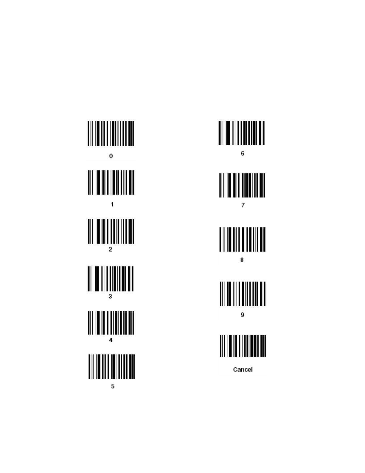
Appendix E Numeric Bar Codes
For parameters requiring specific numeric values, scan the appropriate
numeric bar code.
46 | APPENDIX E: NUMERIC BAR CODES
Page 47

Appendix F Troubleshooting
SYMPTOM:
Nothing happens when I follow the operating instructions, or
the scanner displays erratic behavior (laser does not come on,
scanner emits frequent beeps).
POSSIBLE REASONS SOLUTION
No power to the scanner. Check the system power. Ensure the power
supply is connected if your configuration
requires a power supply.
Interface/power cables are loose.
SYMPTOM:
Laser comes on, but symbol does not decode.
POSSIBLE REASONS SOLUTION
Scanner is not programmed to read
the bar code symbology.
Bar code symbol/label is unreadable. Check the symbol to make sure it is not
Distance between scanner and bar
code is incorrect.
SYMPTOM:
Symbol is decoded, but not transmitted to the host.
POSSIBLE REASONS SOLUTION
SocketScan is not running on the
host device.
SYMPTOM:
Symbol LS-2208 gun is attached to the cable, but it will not operate.
POSSIBLE REASONS SOLUTION
The standard Symbol LS-2208 is not
supported by Socket’s CF card and
cable.
Check for loose cable connections.
Be sure the scanner is programmed to read
the type of bar code you are scanning.
Refer to Appendix C, “Default
Parameters,” to see the default
symbologies.
defaced. Try scanning test symbols of the
same bar code type.
Move the scanner closer to or further from
the bar code.
Launch SocketScan from the Programs
screen or desktop of the host device.
Use only Socket’s S-2208 gun with the
Socket GS 2E CF card and cable.
APPENDIX F: TROUBLESHOOTING | 47
Page 48

Appendix G Technical Support
If you have trouble installing or using the GS 2E, Socket has two technical
support resources to help you. Please note that technical support is available
in English only.
Socket On-Demand Support (SOS)
1.
Socket On-Demand Support is an interactive technical
support program that focuses in on your specific problem
to provide the answers you need. SOS provides immediate
service and is the best place to start for technical support. To access
SOS, visit:
www.socketcom.com/support. Click on the SOS icon.
If SOS cannot solve your problem, end the session by submitting an
email inquiry to a Socket technical support engineer as prompted. Your
interactive session will be saved for reference.
48 | APPENDIX E
Page 49

Live Technical Support
2.
IMPORTANT! To obtain technical support, you must first register
your product online at
www.socketcom.com/prodreg.
After you register your product, log in and click on the Technical
Support tab. Click New Trouble Ticket. Follow the online process to
submit an email request for technical support.
If we are unable to resolve your support inquiry via email, we can
arrange for a technical support representative to call you at a specific
time.
Note: If you have a damaged scanner and want to return it to Socket for
servicing or replacement, SEND THE SCANNER BACK IN THE
ORIGINAL PACKAGING. It is the approved shipping container.
APPENDIX G: TECHNICAL SUPPORT| 49
Page 50

Aperture
AIM
ASCII
Autodiscrimination
Bar
Bar Code
Density
Bar Height
Bar Width
Baud Rate
Bit
Byte
Appendix H Glossary
A
The opening in an optical system defined by a lens or baffle that
establishes the field of view.
Auto Identification Machinery
American Standard Code for Information Interchange. A 7 bit-plusparity code representing 128 letters, numerals, punctuation marks,
and control characters. It is a standard data transmission code in the
U.S.
The ability of an interface controller to determine the code type of a
scanned bar code. After this determination is made, the information
content is decoded.
B
The dark element in a printed bar code symbol.
The number of characters represented per unit of measurement
(e.g., characters per inch).
The dimension of a bar measured perpendicular to the bar width.
Thickness of a bar measured from the edge closest to the symbol
start character to the trailing edge of the same bar.
A measure of the data flow or number of signaling events occurring
per second. When one bit is the standard "event," this is a measure
of bits per second (bps). For example, a baud rate of 50 means
transmission of 50 bits of data per second.
Binary digit. One bit is the basic unit of binary information.
Generally, eight consecutive bits compose one byte of data. The
pattern of 0 and 1 values within the byte determines its meaning.
On an addressable boundary, eight adjacent binary digits (0 and 1)
combined in a pattern to represent a specific character or numeric
value. Bits are numbered from the right, 0 through 7, with bit 0 the
loworder bit. One byte in memory is used to store one ASCII
character.
50 | APPENDIX H: GLOSSARY
Page 51

CDRH
CDRH Class 1
CDRH Class 2
Character
Character Set
Check Digit
Codabar
Code 128
Code 3 of 9
(Code 39)
Code 93
Code Length
Continuous
Code
C
Center for Devices and Radiological Health. A federal agency
responsible for regulating laser product safety. This agency
specifies various laser operation classes based on power output
during operation.
This is the lowest power CDRH laser classification. This class is
considered intrinsically safe, even if all laser output were directed
into the eye’s pupil. There are no special operating procedures for
this class.
No additional software mechanisms are needed to conform to this
limit. Laser operation in this class poses no danger for unintentional
direct human exposure.
A pattern of bars and spaces which either directly represents data or
indicates a control function, such as a number, letter, punctuation
mark, or communications control contained in a message.
Those characters available for encoding in a particular bar code
symbology.
A digit used to verify a correct symbol decode. The scanner inserts
the decoded data into an arithmetic formula and checks that the
resulting number matches the encoded check digit. Check digits are
required for UPC but are optional for other symbologies. Using
check digits decreases the chance of substitution errors when a
symbol is decoded.
A discrete self-checking code with a character set consisting of
digits 0 to 9 and six additional characters: ( - $ : / , +).
A high density symbology which allows the controller to encode all
128 ASCII characters without adding extra symbol elements.
A versatile and widely used alphanumeric bar code symbology with
a set of 43 character types, including all uppercase letters, numerals
from 0 to 9, and 7 special characters (- . / + % $ and space). The
code name is derived from the fact that 3 of 9 elements representing
a character are wide, while the remaining 6 are narrow.
An industrial symbology compatible with Code 39 but offering a
full character ASCII set and a higher coding density than Code 39.
Number of data characters in a bar code between the start and stop
characters, not including those characters.
A bar code or symbol in which all spaces within the symbol are
parts of characters. There are no intercharacter gaps in a continuous
code. The absence of gaps allows for greater information density.
APPENDIX H: GLOSSARY | 51
Page 52

Dead Zone
Decode
Decode
Algorithm
Depth of Field
Discrete Code
Discrete 2 of 5
EAN
Element
Encoded Area
Host Computer
IEC*
IEC (825)
Class 1
An area within a scanner’s field of view, in which specular
reflection may prevent a successful decode. This usually occurs
when the oscillating laser beam is perpendicular (± 5°) to the target
code.
To recognize a bar code symbology (e.g., UPC/EAN) and then
analyze the content of the specific bar code scanned.
A decoding scheme that converts pulse widths into data
representation of the letters or numbers encoded within a bar code
symbol.
The range between minimum and maximum distances at which a
scanner can read a symbol with a certain minimum element width.
A bar code or symbol in which the spaces between characters
(intercharacter gaps) are not part of the code.
A binary bar code symbology representing each character by a
group of five bars, two of which are wide. The location of wide
bars in the group determines which character is encoded; spaces are
insignificant. Only numeric characters (0 to 9) and START/STOP
characters may be encoded.
European Article Number. This European/International version of
the UPC provides its own coding format and symbology standards.
Element dimensions are specified metrically. EAN is used
primarily in retail.
Generic term for a bar or space.
Total linear dimension occupied by all characters of a code pattern,
including start/stop characters and data.
A computer that serves other terminals in a network, providing such
services as computation, database access, supervisory programs,
and network control.
International Electrotechnical Commission. This international
agency regulates laser safety by specifying various laser operation
classes based on power output during operation.
This is the lowest power IEC laser classification. Conformity is
ensured through a software restriction of 120 seconds of laser
operation within any 1000 second window and an automatic laser
shutdown if the scanner’s oscillating mirror fails.
52 | APPENDIX H: GLOSSARY
D
E
H, I
Page 53

2DSC Scanner
Intercharacter
Gap
Interleaved Bar
Code
Interleaved
2 of 5
*LASER
Laser Diode
Laser Scanner
LED Indicator
MIL
Misread
(Misdecode)
An electronic device used to scan bar code symbols by analyzing a
digital image of the bar code. Its components are:
1. CMOS camera – size and resolution of captured image varies
2. Auxiliary lighting
The space between two adjacent bar code characters in a discrete
code.
A bar code in which characters are paired together, using bars to
represent the first character and the intervening spaces to represent
the second.
A binary bar code symbology representing character pairs in groups
of five bars and five interleaved spaces. Interleaving provides for
greater information density. The location of wide elements (bar/
spaces) within each group determines which characters are
encoded. This continuous code type uses no intercharacter spaces.
Only numeric (0 to 9) and START/STOP characters may be
encoded.
L
The laser is an intense light source. Light from a laser is all the
same frequency, unlike the output of an incandescent bulb. Laser
light is typically coherent and has a high energy density.
*Light Amplification by Stimulated Emission of Radiation
A gallium-arsenide semiconductor type of laser connected to a
power source to generate a laser beam. This laser type is a compact
source of coherent light.
An electronic device used to scan bar code symbols and produce a
digitized pattern that corresponds to the bars and spaces of the
symbol. Its three main components are:
1. Light source (laser or photoelectric cell) - illuminates a bar code.
2. Photodetector - registers the difference in reflected light (more
light reflected from spaces).
3. Signal conditioning circuit - transforms optical detector output
into a digitized bar pattern.
A semiconductor diode (LED - Light Emitting Diode) used as an
indicator, often in digital displays. The semiconductor uses applied
voltage to produce light of a certain frequency determined by the
semiconductor’s particular chemical composition.
M, N
1 mil = 1 thousandth of an inch.
A condition which occurs when the data output of a reader or
interface controller does not agree with the data encoded within a
bar code symbol.
APPENDIX H: GLOSSARY | 53
Page 54

Nominal
Nominal Size
Percent Decode
Print Contrast
Signal (PCS)
Programming
Mode
Quiet Zone
Reflectance
Resolution
RSS
Scan Area
Scanning Mode
Scanning
Sequence
Self-Checking
Code
Space
The exact (or ideal) intended value for a specified parameter.
Tolerances are specified as positive and negative deviations from
this value.
Standard size for a bar code symbol. Most UPC/EAN codes are
used over a range of magnifications (e.g., from 0.80 to 2.00 of
nominal).
The average probability that a single scan of a bar code would
result in a successful decode. In a well-GS 2E, that probability
should approach near 100%.
Measurement of the contrast (brightness difference) between the
bars and spaces of a symbol. A minimum PCS value is needed for a
bar code symbol to be scannable. PCS = (RL - RD) / RL, where RL
is the reflectance factor of the background and RD the reflectance
factor of the dark bars.
The state in which a scanner is configured for parameter values.
See SCANNING MODE.
A clear space, containing no dark marks, which precedes the start
character of a bar code symbol and follows the stop character.
Amount of light returned from an illuminated surface.
The narrowest element dimension which is distinguished by a
particular reading device or printed with a particular device or
method.
Reduced Space Symbology: A family of space efficient
symbologies developed by UCC.EAN.
Area intended to contain a symbol.
The scanner is energized, programmed, and ready to read a bar
code.
A method of programming or configuring parameters for a bar code
reading system by scanning bar code menus.
A symbology that uses a checking algorithm to detect encoding
errors within the characters of a bar code symbol.
The lighter element of a bar code formed by the background
between bars.
54 | APPENDIX H: GLOSSARY
P
Q, R
S
Page 55

Specular
Reflection
Start/Stop
Character
Substrate
Symbol
Symbol Aspect
Ratio
Symbol Height
Symbol Length
Symbology
Tolerance
UPC
Visible Laser
Diode (VLD)
The mirror-like direct reflection of light from a surface, which can
cause difficulty decoding a bar code.
A pattern of bars and spaces that provides the scanner with start and
stop reading instructions and scanning direction. The start and stop
characters are normally to the left and right margins of a horizontal
code.
A foundation material on which a substance or image is placed.
A scannable unit that encodes data within the conventions of a
certain symbology, usually including start/stop characters, quiet
zones, data characters, and check characters.
The ratio of symbol height to symbol width.
The height of the bars in a bar code symbol.
Length of symbol measured from the beginning of the quiet zone
(margin) adjacent to the start character to the end of the quiet zone
(margin) adjacent to a stop character.
The structural rules and conventions for representing data within a
particular bar code type (e.g. UPC/EAN, Code 39).
T, U, V
Allowable deviation from the nominal bar or space width.
Universal Product Code. A relatively complex numeric symbology.
Each character consists of two bars and two spaces, each of which
is any of four widths. The standard symbology for retail food
packages in the United States.
A solid state device which produces visible laser light.
APPENDIX H: GLOSSARY | 55
Page 56

Limited Warranty
Socket Communications Incorporated (Socket) warrants this product against defects
in material and workmanship, under normal use and service, for the following
period from the date of purchase:
Plug-in card and cable: Three years
Laser Scanning Gun: Three years
Incompatibility is not a defect covered by Socket’s warranty. During the warranty
period, Socket will, at its option, repair or replace the defective product at no charge
when furnished with proof of retail purchase, provided that you deliver the product
to Socket or to an authorized Socket Service Center.
The returned product must be accompanied by a return material authorization
(RMA) number issued by Socket or by Socket's Authorized Service Center. If you
ship the product, you must use the original container or equivalent and you must pay
the shipping charges to Socket. Socket will pay shipping charges back to any
location in the contiguous United States. This warranty applies only to the original
retail purchaser and is not transferable.
Socket may, at its option, replace or repair the product with new or reconditioned
parts and the returned product becomes Socket's property. Socket warrants the
repaired or replaced products to be free from defects in material or workmanship for
ninety (90) days after the return shipping date, or for the duration of the original
warranty period, whichever is greater.
This warranty does not cover the replacement of products damaged by abuse,
accident, misuse or misapplication, nor as a result of service or modification other
than by Socket.
SOCKET IS NOT RESPONSIBLE FOR INCIDENTAL OR CONSEQUENTIAL
DAMAGES RESULTING FROM BREACH OF ANY EXPRESS OR IMPLIED
WARRANTY, INCLUDING DAMAGE TO PROPERTY AND, TO THE EXTENT
PERMITTED BY LAW, DAMAGES FOR PERSONAL INJURY. THIS
WARRANTY IS IN LIEU OF ALL OTHER WARRANTIES INCLUDING
IMPLIED WARRANTIES OF MERCHANTABILITY AND FITNESS FOR A
PARTICULAR PURPOSE.
Some states do not allow limitation of implied warranties, or the exclusion or
limitation of incidental or consequential damages, so that the above limitations or
exclusions may not apply to you. This warranty gives you specific legal rights and
you may also have other rights which vary from state to state.
This product may contain fully tested, recycled parts, warranted as if new.
For warranty information, email info@socketcom.com.
56
Page 57

Limited Software Warranty
LIMITED WARRANTY. SOCKET warrants that the original disk or CD ROM is
free from defects for 90 days from the date of delivery of the SOFTWARE.
CUSTOMER REMEDIES. SOCKET’S entire liability and your exclusive remedy
shall be, at SOCKET’S option, either (a) return of the price paid or (b) replacement
of the SOFTWARE which does not meet SOCKET’S Limited Warranty and which
is returned to SOCKET with a copy of your receipt. Any replacement SOFTWARE
will be warranted for the remainder of the original warranty period or 30 days,
whichever is longer. THESE REMEDIES ARE NOT AVAILABLE OUTSIDE OF
THE UNITED STATES OF AMERICA.
NO OTHER WARRANTIES. SOCKET disclaims all other warranties, either
express or implied, including but not limited to implied warranties of
merchantability and fitness for a particular purpose, with respect to the
SOFTWARE and the accompanying written materials. This limited warranty gives
you specific legal rights. You may have others which vary from state to state.
NO LIABILITY FOR CONSEQUENTIAL DAMAGES. In no event shall SOCKET
or its suppliers be liable for any damages whatsoever (including, without limitation,
damages for loss of business profits, business interruption, loss of business
information, or other pecuniary loss) arising out of the use of or inability to use the
SOFTWARE, even if SOCKET has been advised of the possibility of such
damages. Because some states do not allow the exclusion or limitation of liability
for consequential or incidental damages, the above limitation may not apply to you.
EXPORT LAW ASSURANCES. You may not use or otherwise export or reexport
the SOFTWARE except as authorized by United States law and laws of the
jurisdiction in which the SOFTWARE was obtained. In particular, but without
limitation, none of the SOFTWARE may be used or otherwise exported or
reexported (a) into (or to a national or resident of) a United States embargoed
country or (b) to anyone on the U.S. Treasury Department’s list of Specially
Designated Nationals or the U.S. Department of Commerce’s Table of Denial
Orders. By using the SOFTWARE, you represent and warrant that you are not
located in, under control of, or a national or resident of any such country or on any
such list.
GOVERNMENT END USERS. If the SOFTWARE is supplied to the U. S.
Government, the SOFTWARE is classified as “restricted computer software” as
defined in clause 52.227-19 of the FAR. The U. S. Government ‘s rights to the
SOFTWARE are as provided in clause 52.227-19 of the FAR.
CONTROLLING LAW AND SEVERABILITY. This License shall be governed by
the laws of the United States and the State of California. If for any reason a court of
competent jurisdiction finds any provision, or portion thereof, to be unenforceable,
the remainder of this License shall continue in full force and effect.
57
Page 58

Regulatory Compliance
This equipment has been tested and found to comply with the limits for a
Class B digital device, pursuant to Part 15 of the FCC rules. This equipment
is also CE EN55024:1998 and C-TICK compliant. These limits are
designed to provide reasonable protection against harmful interference
when the equipment is operated in a commercial environment.
This equipment generates, uses, and can radiate radio frequency energy
and, if not installed and used in accordance with the instruction manual,
may cause harmful interference to radio communications. Operation of this
equipment in a residential area may cause harmful interference in which
case the user will be required to correct the interference at his or her own
expense.
If this equipment does cause harmful interference to radio or television
reception, which can be determined by turning the equipment off and on,
the user may try to correct the interference by doing any of the following:
• Reorient or relocate the receiving antenna of the radio or television.
• Increase the distance separating the equipment and the receiver.
• Connect the equipment to an outlet on a different branch circuit than
that of the receiver.
• Consult the dealer or an experienced radio/TV technician for help.
The user may find the following booklet helpful:
How to Identify and Resolve Radio-TV Interference Problems
This booklet is available from the U.S. Government Printing Office,
Washington, D.C. 20402
LASER DEVICES: Socket products using lasers comply with US
21CFR1040.10, Subchapter J and IEC825/EN 60 825 (or IEC825-1/EN 60
825-1, depending on date of manufacture). The laser classification is
marked on one of the labels on the product.
Class 1 Laser devices are not considered to be hazardous when used for
their intended purpose. The following statement is required to comply with
US and international regulations.
Caution: Use of controls, adjustments or performance of procedures other
than those specified herein may result in hazardous laser light exposure.
Class 2 laser scanners use a low power, visible light diode. As with any
very bright light source, such as the sun, the user should avoid staring
directly into the light beam. Momentary exposure to a Class 2 laser is not
known to be harmful.
58
Page 59

PRODUCT DISPOSAL: This product must not be disposed of with
municipal waste. It is your responsibility to dispose of your waste
equipment by handing it over to a designated collection point for the
recycling of waste electrical and electronic equipment.
59
Page 60

© Socket Communications, Inc. 8/2005 Printed in U.S.A. © Socket Communications, Inc. 8/2005 Printed in U.S.A.
 Loading...