

Page 1
CHARGING MOUNT
USER GUIDE
ATTACHABLE
Page 2
Charging Mount
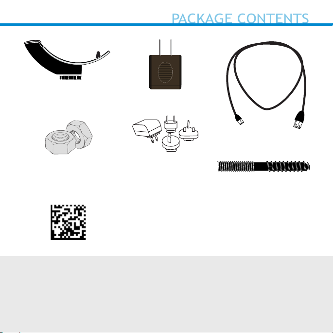
PACKAGE CONTENTS
or
USB Charging Cable
2 x Hex Nuts
AC Adapter
Use the plug that is
regionally appropriate
Hanger Bolt
Command Barcode label
to place on mount
© 2017 Socket Mobile, Inc. All rights reserved. Socket, the Socket logo, and
SocketScan are registered trademarks or trademarks of Socket Mobile, Inc. USA,
and any use by Socket Mobile, Inc. is under license. All other trademarks and
trade names contained herein may be those of their respective owners.
Page 3
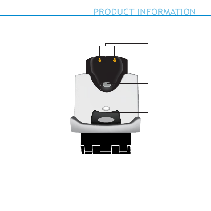
LED*
PRODUCT INFORMATION
Charging Mount
*Illuminates Red when connected to AC adapter.
Charging Pins
Magnet
Hook
3
Page 4
B.
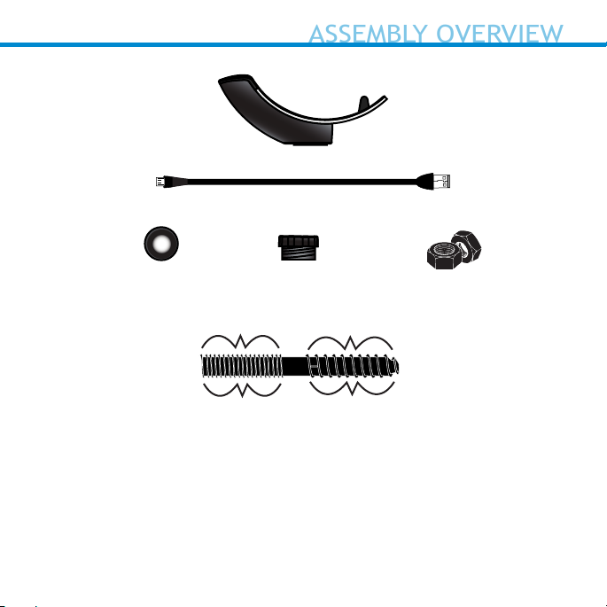
ASSEMBLY OVERVIEW
A.
C.
D. E.
1/4” - 20
Machine
bolt thread
F.
Screws into
camera mount or
Charging Mount
A. Charging Mount
B. Micro USB (2m)
C. Cushion Crown
D. Pem Cap / Camera Mount*
Tapered
lag-screw
Screws into
wooden
surface
E. 2 x Hex Nuts
F. Hanger Bolt**
*Optional for Camera Mount (See page 9)
**Optional for table mount (see page 8)
4
Page 5
A.
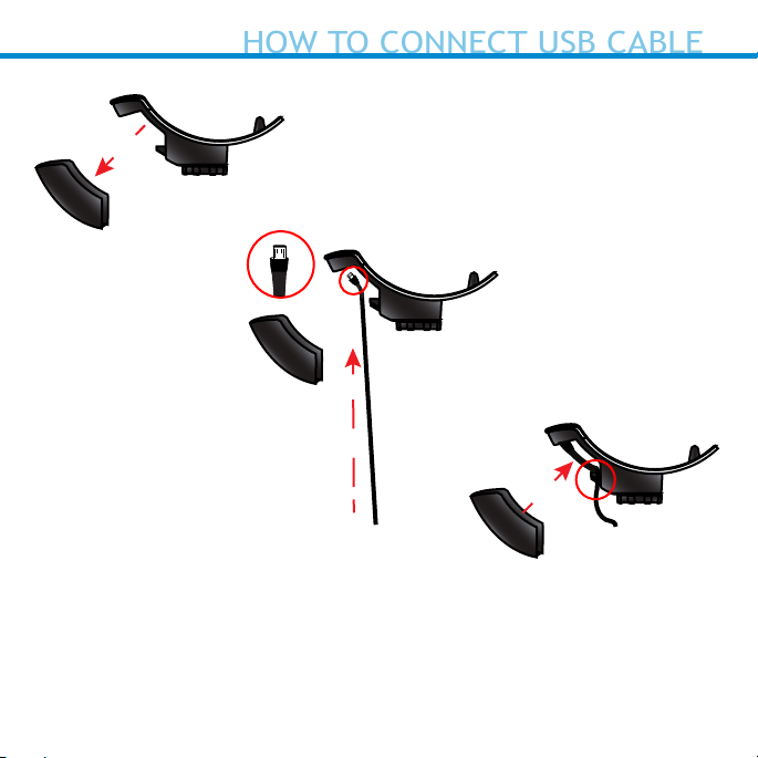
HOW TO CONNECT USB CABLE
B.
A. Remove Micro USB cover.
B. Insert Micro USB connector into port and t usb
cable into the cord keeper.
C. Secure the cable to prevent from movement.
C.
5
Page 6
When charging the scanner, make
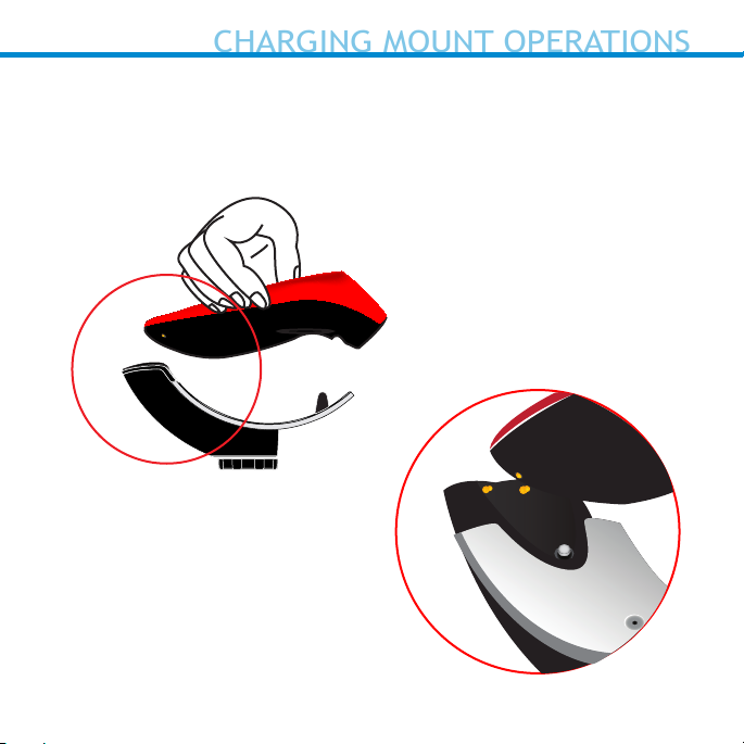
CHARGING MOUNT OPERATIONS
sure the charging pins on the Mount
and the scanner make contact with
each other and the red LED on the
Mount is illuminated.
“Beep
Beep”*
6
Page 7

4-6 inches
CHARGING MOUNT OPERATIONS
(10 - 15 cm)
7
Page 8

Charging Mount Modes
COMMAND BARCODES
Mobile Mode - Normal (default)* Scanning
this bar code will enable the scanner to
enter mobile mode. It will always be in
manual trigger mode even when placed in
the mount or cradle.
*Scanner Factory Reset returns to Mobile
Mode.
Auto Mode (Presentation Mode)
Scanning this bar code will enable the
scanner to enter auto mode. When the
scanner is in auto mode, it will switch to
presentation trigger mode when it
detects power on the cradle pins. When
the scanner is removed from the cradle it
will remain in presentation trigger mode
until the users presses the trigger. At that
point it will switch to normal manual trigger mode. Auto Mode command barcode is
also printed on the product label.
#FNB 41FBA50000#
#FNB 41FBA50003#
8
Page 9

Auto Mode (In the Mount)
AUTO MODE
Notication
Action Behavior
Place
Scanner in
the Mount
Place a
barcode in
the
Scanners
Field of
View
Auto Mode: Bar Codes placed in the Scanner’s eld of view are
automatically scanned.
*Note: 7Qi/7Xi/D750 will beep High-high tone even if the Scanner is
Power Off (to indicate charging)
*Lights for D750 will function as described in the D750 user guide.
Scanner
switches to
Presentation
Mode
Decode Bar
Code
Beep
Pattern
High-high
tone conrms
proper seating*
1 Beep when
Data
successfully
scanned
LED Activity Vibrate
Battery
Status LED
is Disabled
Green LED
blinks (while
scanning)
None
None
9
Page 10

Mobile Mode (Not in the Mount)
AUTO MODE
Notication
Action Behavior
Remove the
Scanner from
the Mount
and press the
Trigger button
Press the
Trigger
button
Mobile Mode: Pressing the Trigger button initiates a scan.
Scanner
switches
to Mobile
Mode
Decode
Bar Code
Beep
Pattern
None Battery
1 Beep
when Data
successfully
scanned
LED
Activity
Status LED
is Enabled
Green LED
blinks (while
scanning)
Vibrate
Enabled
Vibrate
when Data
successfully
scanned
10
Page 11

1. Pair and connect the 7Qi/7Xi/D750 to your device prior to placing the
AUTO MODE (CONTINUED)
scanner in Auto Mode. The Scanner is not discoverable when in Auto
Mode and in the Mount. This facilitates a fast connection to the
current connected device when powered on (for example the start of
the new business day).
2. The Trigger button must be pressed to disable Presentation Mode
(and enable Mobile Mode) after the scanner is removed from the
Mount.
3. The Scanner will not turn off when its in Presentation Mode and in
the Mount under AC Power.
4. To avoid excessive power drain, the scanner should not be left out of
the Mount in Auto Mode. Either press the Trigger button or Power off
the scanner.
11
Page 12

We include a Hanger Bolt to secure the Charging Mount directly to a
INSTRUCTIONS FOR MOUNTING ON WOODEN SURFACE
wooden surface. Since the Pem Cap connects to a Camera Mount, popular with IP Cameras, many OEM solutions are
available which do not require the Hanger Bolt.
If you plan to use the Hanger Bolt follow the special instructions for
mounting on a wooden surface.
If you have many Hanger Bolts to install, you may want to use a 1/4”-20
Hanger Bolt Driver with an Electric Screw Driver. (Image below)
“
1
/
4
12
Page 13

1/4“ x 13/4”
INSTRUCTIONS FOR MOUNTING ON WOODEN SURFACE
Special instructions for mounting on wooden surface:
1. Screw two Hex nuts (1/4”-20 thread, not included) onto the
machine-threaded portion of the Hanger Bolt.
2. Use an open-ended wrench to lock the nuts against each other.
3. Drill a pilot hole into the surface you wish to place the
Charging Mount.
4. Thread the lag portion of the Hanger Bolt into this surface as far as
you can by hand.
5. Use a wrench on the outermost nut to drive the Hanger Bolt into the
surface.
6. When the lag portion is sufciently threaded, unjam the two nuts
from each other, and run them off (unscrew them).
13
Page 14

A.
CONFIGURATION WHEN USING A CAMERA MOUNT
B.
A. Attach the Pem cap to
your Camera Mount
(1/4” - 20, 3/4” depth
thread) and turn to the
right.
B. Attach the Charging
Mount to the Pem cap.
14
Page 15

Dimensions
PRODUCT SPECIFICATIONS
COMPLIANCE STATEMENT
Charging Mount Width 1.80 in (46 mm)
Charging Mount Length 5.50 in (140 mm)
Antimicrobial Rating JLS z2801:2000 Test: 2.49 on MRSA 6.07
when cleaned with SaniCloth Plus cloth
wipes Biosafe HM4100, EPA#83019-1
CE MARKING AND EUROPEAN UNION COMPLIANCE
The unit under test was found compliant with all the applicable Directives, 2004/108/EC and 2006/95/EC.
WASTE ELECTRICAL AND ELECTRONIC EQUIPMENT
The WEEE directive places an obligation on all EU-based manufacturers and importers to take-back electronic products at the end of their
useful life.
ROHS STATEMENT OF COMPLIANCE
This product is compliant to Directive 2011/65/EU.
NON-MODIFICATION STATEMENT
Changes or modications not expressly approved
by the party responsible for compliance.
RoHS
15
Page 16

Technical Support & Product Registration:
HELPFUL RESOURCES
http://support.socketmobile.com
Phone: 800-279-1390 +1-510-933-3020 (worldwide)
Socket Mobile Developer Program:
Learn more at: https://www.socketmobile.com/developers
The User’s Guide (full installation and usage instructions) and Command
Barcodes (Advanced Scanner Congurations) can be download at:
https://www.socketmobile.com/support/downloads
16
Page 17

Page 18

2017
6430-00362E Printed in U.S.A.
 Loading...