

Page 1
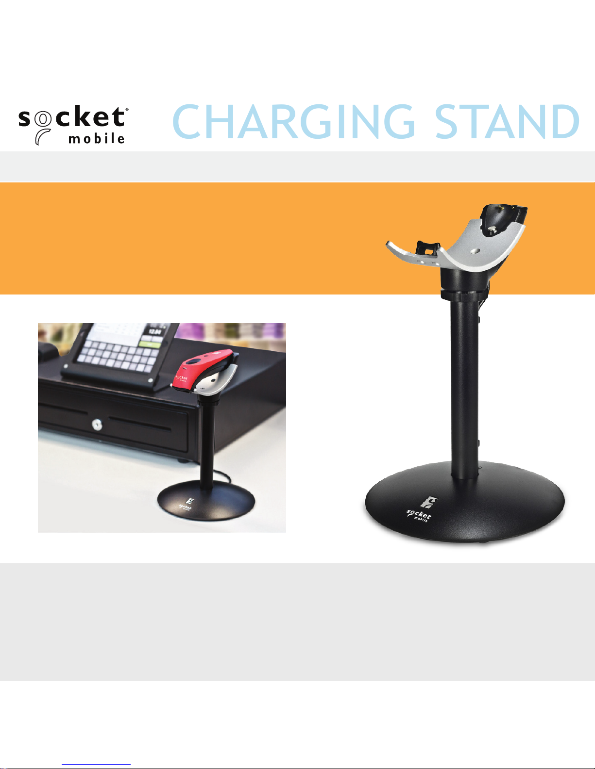
Charging Stand SKU# AC4076-1538 P/N 9010-01538
ATTACHABLE
CHARGING STAND
USER GUIDE
Page 2
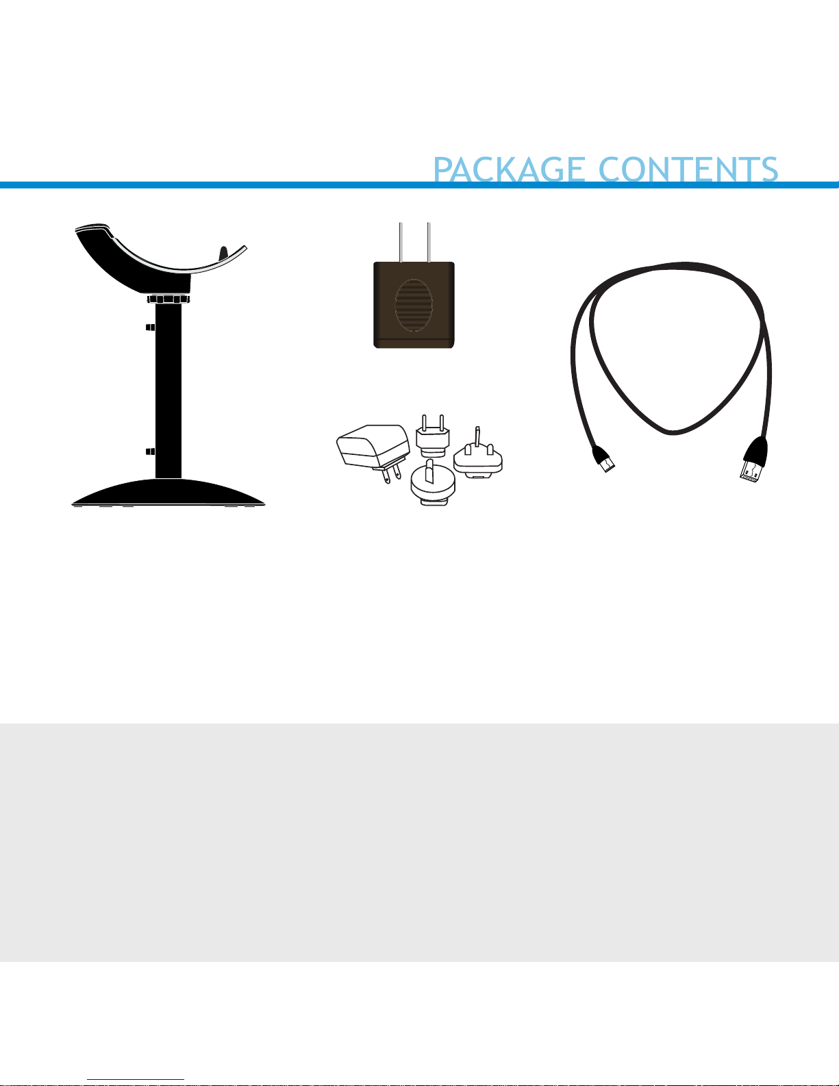
USB Charging CableCharging Stand
AC Adapter
*Use the plug that is
regionally appropriate
©2017 Socket Mobile, Inc. All rights reserved. Socket, the Socket logo, and
SocketScan are registered trademarks or trademarks of Socket Mobile, Inc. The
Bluetooth word mark and logo are registered trademarks of the Bluetooth SIG,
Inc. USA, and any use by Socket Mobile, Inc. is under license. All other
trademarks and trade names contained herein may be those of their respective
owners.
Thank you for choosing Socket Mobile!
Let’s get started!
or
PACKAGE CONTENTS
Page 3
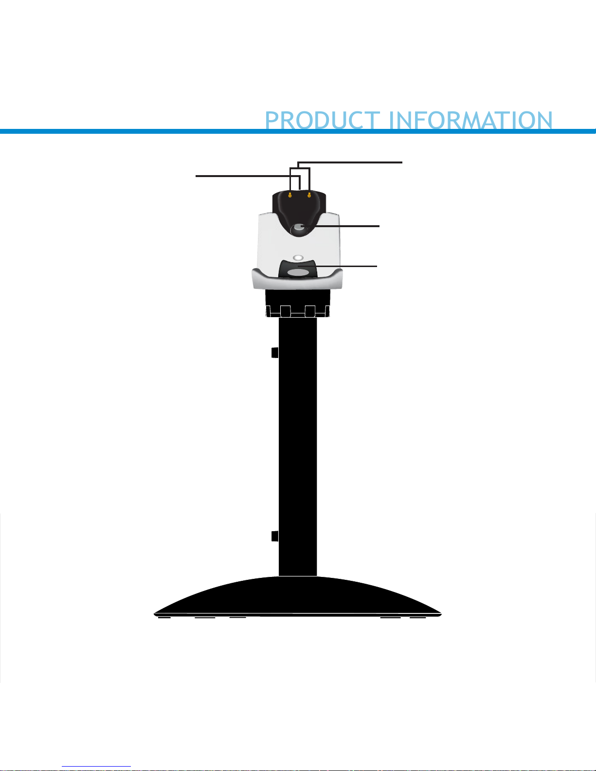
Magnet
Hook
*Illuminates Red when connected to AC Power.
Charging Pins
Light*
3
PRODUCT INFORMATION
Page 4
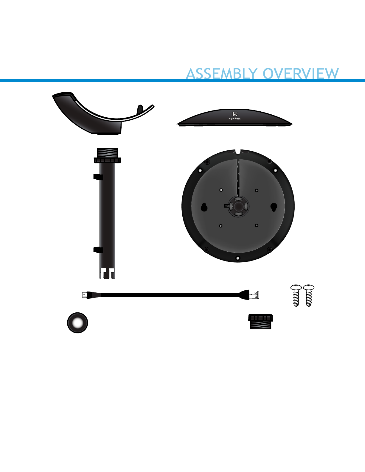
A. Charging Mount
B. Base
C. Post
D. Micro USB (2m)
E. Cushion Crown
F. Pem Cap / Camera Mount*
G. Wood Screws (2)**
A.
C.
D.
F.
G.
E.
B. (Front view)
B. (Bottom view)
4
*Optional for Camera Mount (See page 14)
**Optional for table mount (see page 12)
ASSEMBLY OVERVIEW
Page 5
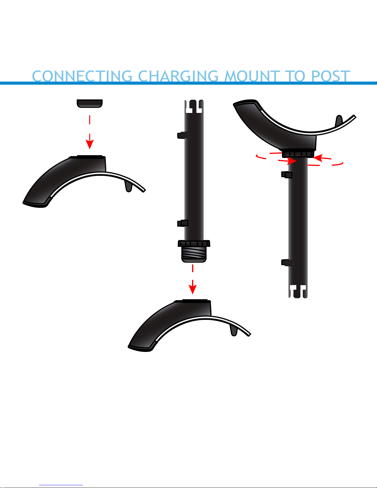
A. Flip the Charging Mount upside down and insert the cushion crown
into the bottom of the Charging Mount.
B. Insert the post into the bottom of the Charging Mount.
C. Turn the washer to the right until it is locked in place.
A.
B.
C.
5
CONNECTING CHARGING MOUNT TO POST
Page 6
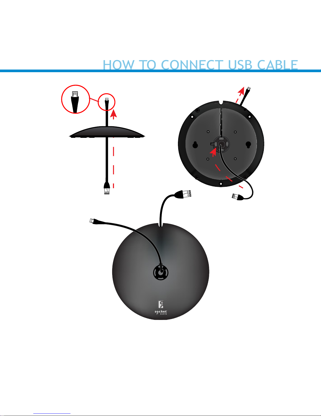
Step 1: Insert Micro USB from under the base.
Step 1
Base (Top View)
Base (Bottom View)
Front
Back
6
HOW TO CONNECT USB CABLE
Page 7

Step 2: Remove Micro USB cover.
Step 3: Insert Micro USB connector into port and t
usb cable into the cord keeper.
Step 4: Leave enough slack to allow freedom of
movement. Place cover.
Step 3
Step 4
7
HOW TO CONNECT USB CABLE
Page 8

Insert the post into the top of the base lining up the marker on the post
to the unlock icon. Push down and turn the post towards the lock icon
until you hear a click.
8
CONNECTING THE POST TO THE BASE
Page 9

1. To unlock, nd the small
latch on the bottom of the
base.
2. Pull the latch back and turn
the post clockwise aligning
the marker with the unlock
icon.
Small latch
Base (Bottom View)
9
HOW TO UNLOCK
Page 10
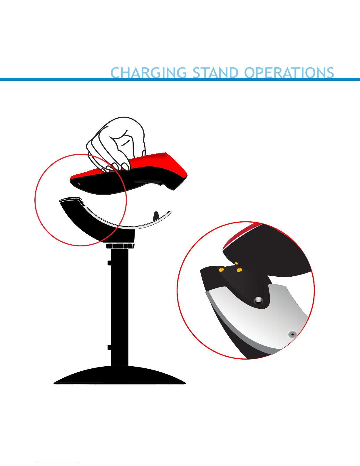
When charging the scanner, make
sure the charging pins on the
stand and the scanner make contact with each other and the red
Light on the stand is illuminated.
10
*CHS 7Qi, 7Xi, D750 only
“Beep
Beep”*
CHARGING STAND OPERATIONS
Page 11

4-6 inches
(10 - 15 cm)
11
CHARGING STAND OPERATIONS
Page 12

12
Two keyholes are provided on the Charging Stand Base for an optional
installation on a wooden surface using the included screws (quantity 2)
and Drill Template.
1. Place the Charging Stand on the Drill Template and situate these
onto the desired location of your surface. Rotate the Stand so that it
aligns with the solid Notch (not the dotted Notch) on the Template.
2. Rotate the Stand/Template combination so the Socket Mobile logo
faces in the direction you want the scanner to face.
3. Tape the Template to the surface and remove the Stand.
4. Drill two
3
/
32” holes through the drill marks on the Template.
5. Tighten the two screws with about
1
/
4” of the screw head exposed.
6. Place the Stand on the template aligned with the dotted Notch.
7. You can now remove (tear away) the Template.
8. Twist the Stand clockwise so the screws lock into the keyholes.
OPTIONAL CHARGING STAND AND TABLE MOUNT
Page 13

13
Magnet Magnet
Magnet
Command Barcode
“Auto Mode”
Keyholes
Notch
OPTIONAL CHARGING STAND AND TABLE MOUNT
Page 14

A. Attach the Pem cap to
your Camera Mount
(1/4” - 20 x 3/4” thread)
and turn to the right.
B. Attach the Charging
Mount to the Pem cap
A.
B.
14
OPTIONAL CONFIGURATION WHEN USING A CAMERA MOUNT
Page 15

Charging Stand Modes
Mobile Mode - Normal (default)* Scanning
this bar code will enable the scanner to
enter mobile mode. It will always be in
manual trigger mode even when placed in
the stand or cradle.
*Scanner Factory Reset returns to Mobile
Mode.
#FNB 41FBA50000#
Auto Mode (Presentation Mode)
Scanning this bar code will enable the
scanner to enter auto mode. When the
scanner is in auto mode, it will switch to
presentation trigger mode when it detects power on the cradle pins. When the
scanner is removed from the cradle it will
remain in presentation trigger mode until
the users presses the trigger. At that point
it will switch to normal manual trigger
mode. Auto Mode command barcode is also
printed on the product label.
#FNB 41FBA50003#
15
COMMAND BARCODES
Page 16

16
Action Behavior
Notication
Beep Pattern Light Activity Vibrate
Place Scanner
in the Stand
Scanner
switches to
Presentation
Mode
High-high tone
conrms proper
seating*
Battery Status
Light is Disabled
None
Place a barcode
in the Scanners
Field of View
Decode Bar
Code
1 Beep when
Data successfully scanned
Green Light
blinks (while
scanning)
None
Action Behavior
Notication
Beep Pattern Light Activity Vibrate
Remove the
Scanner from
the Stand and
press the Trigger button
Scanner
switches to
Mobile Mode
None Battery Status
Light is Enabled
Enabled
Press the Trigger button
Decode Bar
Code
1 Beep when
Data successfully scanned
Green Light
blinks (while
scanning)
Vibrate when
Data successfully scanned
Presentation Mode: Bar Codes placed in the Scanner’s eld of view are automatically scanned.
Mobile Mode: Pressing the Trigger button initiates a scan.
*Note: 7Qi/7Xi will beep High-high tone even if the Scanner is Power Off (to indicate charging)
Auto Mode (In the Stand)
Mobile Mode (Not in the Stand)
AUTO MODE
Page 17

17
1. Pair and connect the 7Qi/7Xi to your device prior to placing the scan-
ner in Auto Mode. The Scanner is not discoverable when in Auto Mode
and in the Stand. This facilitates a fast connection to the current
connected device when powered on (for example the start of the
new business day).
2. The Trigger button must be pressed to disable Presentation Mode
(and enable Mobile Mode) after the scanner is removed from the
Stand.
3. The Scanner will not turn off when its in Presentation Mode and in
the Stand under AC Power.
4. To avoid excessive power drain, the scanner should not be left out of
the Stand in Auto Mode. Either press the Trigger button or Power off
the scanner.
AUTO MODE (CONTINUED)
Page 18

Dimensions
Stand Height 8.75 in (222 mm)
Charging Mount Width 1.80 in (46 mm)
Charging Mount Length 5.50 in (140 mm)
Base Diameter 5.75 in (146mm)
Total Weight
Without Scanner and AC Adapter 16 oz (454 g)
With Scanner and without AC Adapter 17.6 oz (500 g)
Antimicrobial Rating JLS z2801:2000 Test:
2.49 on MRSA 6.07 when
cleaned with SaniCloth
Plus cloth wipes Biosafe
HM4100, EPA#83019-1
18
PRODUCT SPECIFICATIONS
Page 19

Technical Support & Product Registration:
support.socketmobile.com
Phone: 800-279-1390 +1-510-933-3020 (worldwide)
Warranty Checker:
socketmobile.com/warranty-checker
Socket Mobile Developer Program:
Learn more at: socketmobile.com/developers
Download the scanner User Guide (full installation and usage instruc-
tions) and Command Barcodes (Advanced Scanner Congurations) at
socketmobile.com/downloads
19
HELPFUL RESOURCES
Page 20

CE MARKING AND EUROPEAN UNION COMPLIANCE
The unit under test was found compliant with all the applicable Directives, 2004/108/EC and
2006/95/EC.
WASTE ELECTRICAL AND ELECTRONIC EQUIPMENT
The WEEE directive places an obligation on all EU-based manufacturers and importers to
take-back electronic products at the end of their useful life.
ROHS STATEMENT OF COMPLIANCE
This product is compliant to Directive 2011/65/EU.
NON-MODIFICATION STATEMENT
Changes or modications not expressly approved
by the party responsible for compliance.
RoHS
2017 6430-00358C Printed in U.S.A.
COMPLIANCE STATEMENT
 Loading...