

Page 1

Scanning Companion
USB Bluetooth® Adapter
(Part no. 8520-00023)
Plug-in adapter for connecting Windows XP computers to the
Cordless Hand Scanner (CHS) Series 7 or Cordless Ring Scanner
(CRS) Series 9
User’s Guide
Page 2

11/2007 Document # 6410-00176 I
COPYRIGHT NOTICE
Copyright © 2007 Socket Communications, Inc. dba Socket Mobile,
Inc. All rights reserved.
Socket, the Socket logo, Battery Friendly, SocketScan, Cordless
Hand Scanner, Cordless Ring Scanner, Connect!Agent and
SocketScan are registered trademarks or trademarks of Socket
Communications, Inc. dba Socket Mobile, Inc. Bluetooth and the
Bluetooth logos are registered trademarks owned by Bluetooth SIG,
Inc., U.S.A. and licensed to Socket Mobile, Inc. All other brand and
product names are trademarks of their respective holders.
Reproduction of the contents of this manual without the permission
of Socket Mobile is expressly prohibited. Please be aware that the
products described in this manual may change without notice.
Feel free to contact Socket Mobile at:
Socket Mobile, Inc.
39700 Eureka Drive
Newark, CA 94560-4808
USA
Other than the above, Socket Mobile can assume no responsibility
for anything resulting from the application of information contained in
this manual.
Please refrain from any applications of Scanning Companion that are
not described in this manual. Please refrain from disassembling the
adapter. Disassembly of this device will void the product warranty.
You can track new product releases, software updates and technical
bulletins by visiting the Socket Mobile website at:
www.socketmobile.com.
Page 3

TABLE OF CONTENTS
COPYRIGHT NOTICE 2
1 | INTRODUCTION 5
ACTIVEPAIRING
SYSTEM REQUIREMENTS 6
PACKAGE CONTENTS 6
PRODUCT REGISTRATION 6
HARDWARE FEATURES 7
™
6
2 | HARDWARE AND SOFTWARE INSTALLATION 8
STEP 1: INSERT THE INSTALLATION CD 9
STEP 2: PLUG IN SCANNING COMPANION 9
STEP 3: COMPLETE THE FOUND NEW HARDWARE WIZARD 10
3 | MANUAL BLUETOOTH CONNECTIONS 13
STEP 1: TURN ON THE CHS/CRS 14
STEP 2: A
STEP 3: S
STEP 4: C
STEP 5: R
STEP 6: C
A
UTO-RECONNECT 22
D
ISCONNECTING 22
DD CHS/CRS TO MICROSOFT BLUETOOTH UTILITY 14
TART SOCKETSCAN 17
ONFIGURE SCANNER SETTINGS 17
ESTART SOCKETSCAN 19
ONNECT TO CHS/CRS 20
4 | CONNECT!AGENT 23
STEP 1: TURN ON THE CHS/CRS 24
STEP 2: S
STEP 3: C
STEP 4: R
STEP 5: C
A
UTO-RECONNECT 28
D
ISCONNECTING 28
TART SOCKETSCAN 24
ONFIGURE SCANNER SETTINGS 24
ESTART SOCKETSCAN 26
ONNECT TO CHS/CRS 27
5 | ACTIVEPAIRING 29
STEP 1: TURN ON THE CRS 31
STEP 2: A
STEP 3: S
STEP 4: C
STEP 5: R
STEP 6: S
STEP 7: S
STEP 8: E
P
AIRING AND CONNECTING TO ANOTHER COMPUTER 38
A
UTO-RECONNECT 38
DD CRS TO MICROSOFT BLUETOOTH UTILITY 31
TART SOCKETSCAN 34
ONFIGURE SCANNER SETTINGS 34
ESTART SOCKETSCAN 36
TICK ACTIVEPAIRING BAR CODES ONTO COMPUTER 36
CAN INITIATOR BAR CODE 36
NTER PASSKEY 37
3
Page 4

D
ISCONNECTING 38
APPENDICES
A | SPECIFICATIONS 39
B | SAFETY AND USAGE TIPS 41
C | TECHNICAL SUPPORT 43
LIMITED WARRANTY 44
REGULATORY COMPLIANCE 48
4
Page 5
1 | INTRODUCTION
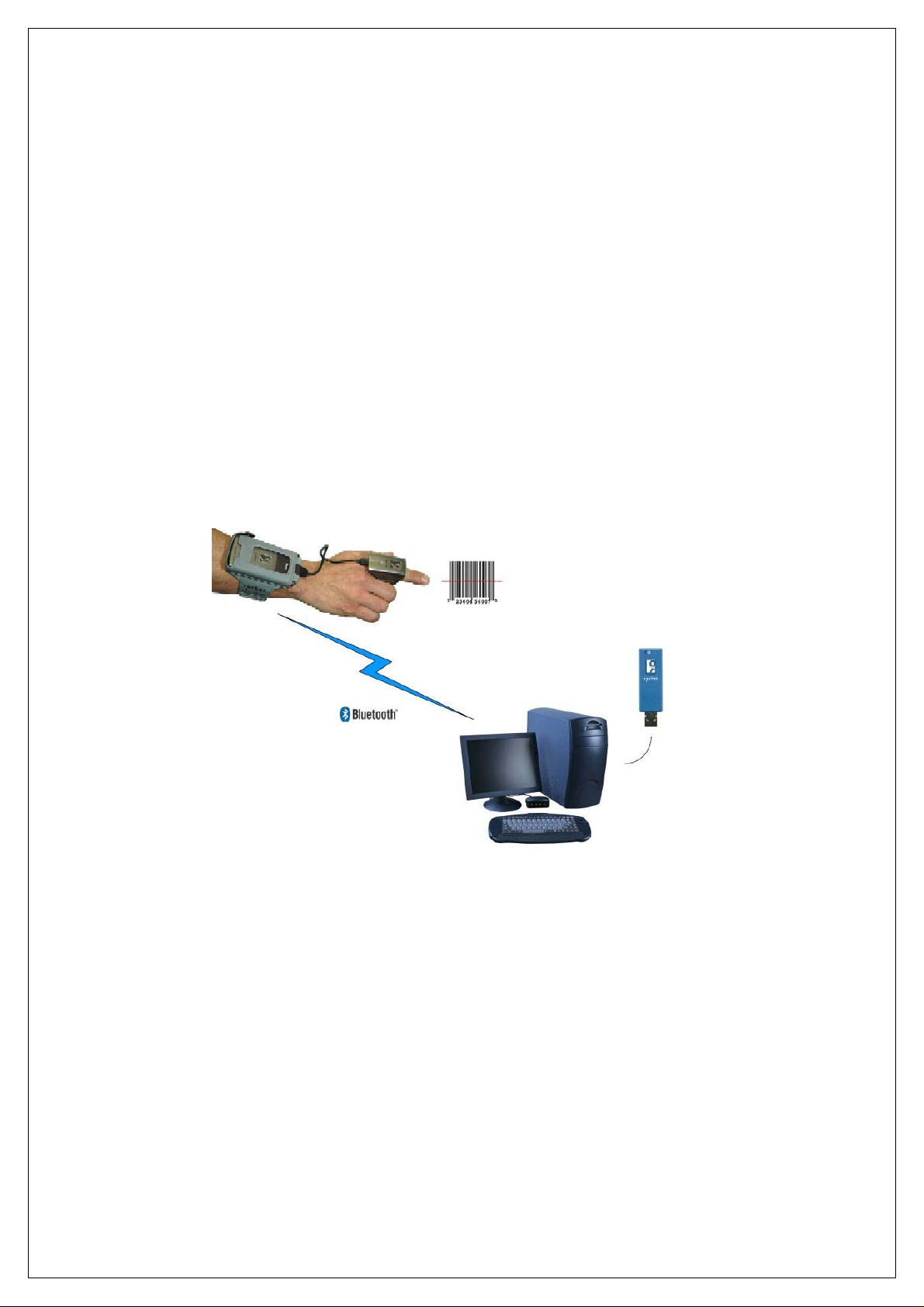
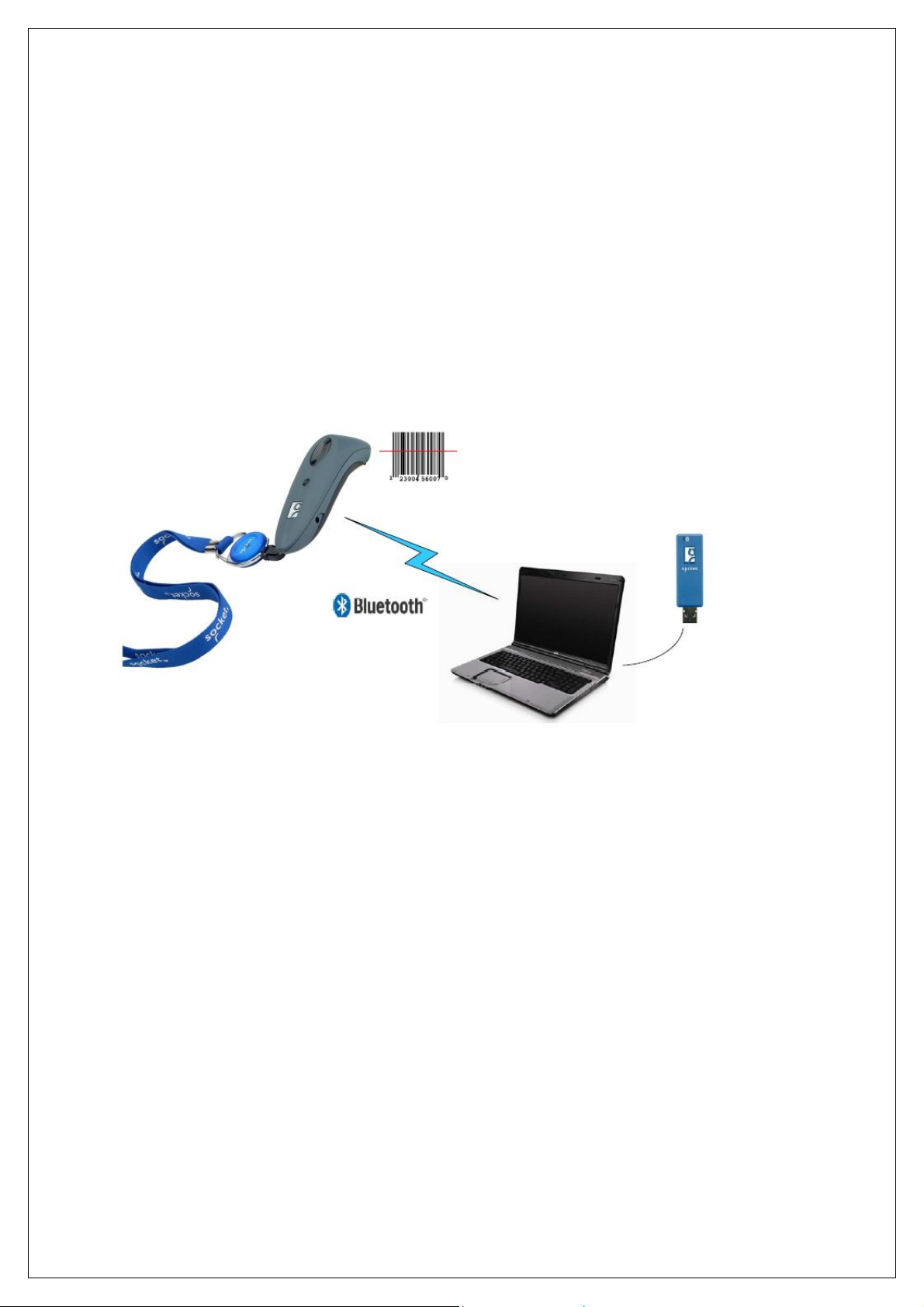
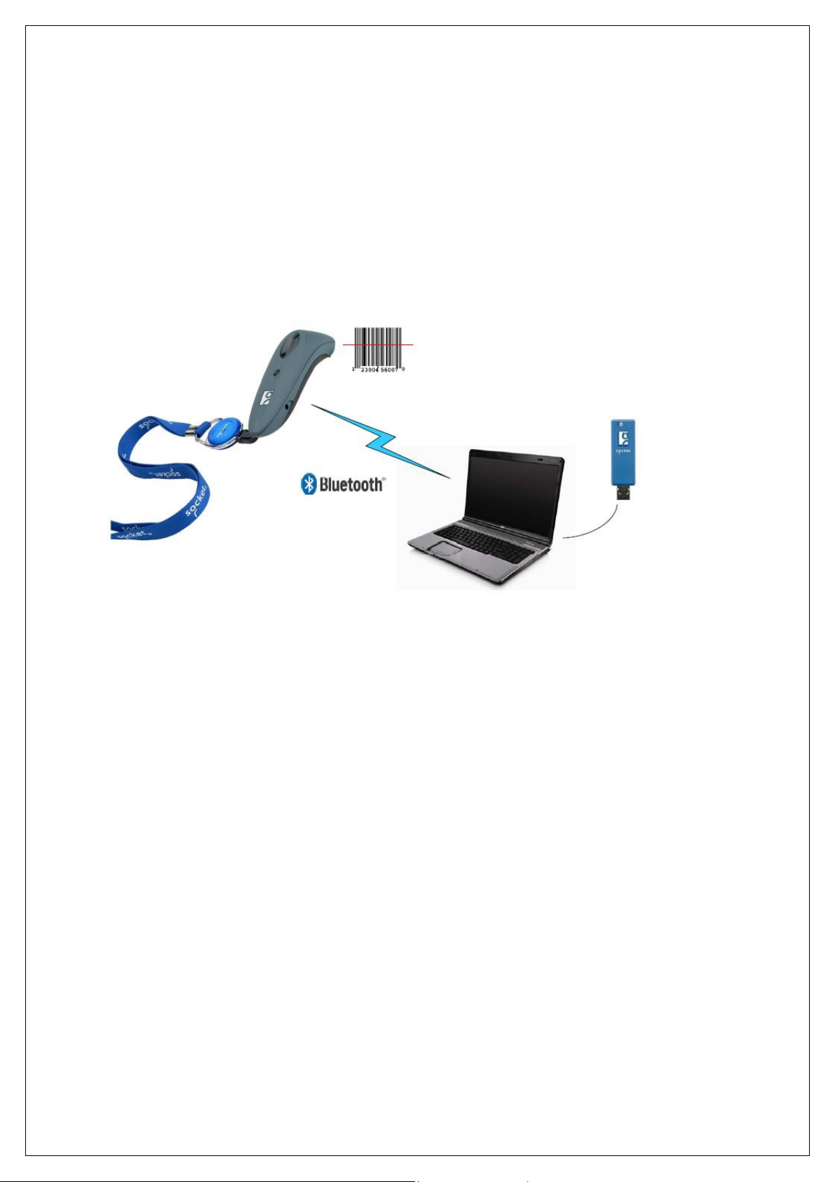
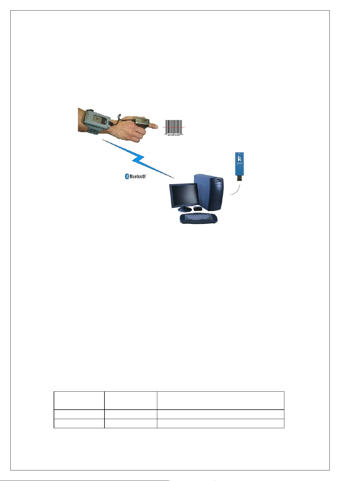
Do you want to use Socket Mobile cordless bar code scanners with
your notebook or desktop computer, but it doesn’t have Bluetooth
built in? Just plug in Scanning Companion, and your computer will be
ready to capture data from the Cordless Hand Scanner (CHS) Series
7 or Cordless Ring Scanner (CRS) Series 9. Scanning Companion
features a USB 2.0 interface and a powerful Class 1 Bluetooth radio
with a range of 100 meters (328 feet).
Eliminate compatibility problems and expensive downtime by using a
Bluetooth adapter and bar code scanner from Socket Mobile, a
name you trust. You’ll have peace of mind knowing Socket Mobile
products are designed to work together for a simple, trouble-free
implementation.
With Scanning Companion, your computer will be ready to capture
bar code data without the hassle or physical limitations of cabled
solutions. This ensures not only optimal efficiency of data collection,
but also eliminates the risk of tripping over cables or getting cables
tangled in industrial equipment.
Scanning Companion is compatible with Socket Mobile
Connect!Agent™ software for automatic connections to your CHS or
CRS.
CHAPTER 1: INTRODUCTION 5
Page 6

ACTIVEPAIRING™
Socket Mobile ActivePairing technology enables you to quickly
pair/unpair the CRS with a computer by simply scanning a special
bar code. It is ideal for users who need to roam from system to
system but still use the same CRS unit. By making Bluetooth
connections easy for any user, ActivePairing helps to eliminate
support costs and downtime in enterprise deployments.
The Scanning Companion package includes labels pre-printed with
ActivePairing bar codes customized for your Scanning Companion.
This makes Scanning Companion ready to deploy out of the box for
implementations with ActivePairing.
Note: ActivePairing does not work with the CHS at this time.
SYSTEM REQUIREMENTS
Your computer should satisfy these requirements:
• Windows Mobile XP or XP Tablet Edition
• Microsoft Bluetooth stack
PACKAGE CONTENTS
The Scanning Companion package includes these items:
• Scanning Companion
• CD containing software (INF file) and user documentation
• ActivePairing bar code labels
• Booklets with copyright, warranty, and regulatory compliance
information
PRODUCT REGISTRATION
Socket highly recommends that all customers register their Socket
products. Registered users receive the following benefits:
• Priority for technical support
• Special offers for future products and upgrades
• The latest new product information.
Register online at: www.socketmobile.com/support/support/new
6
Page 7

HARDWARE FEATURES
Power Status LED
LED Activity Meaning
On (Blue)
Off
Scanning Companion is receiving power from your
computer
Scanning Companion is off
CHAPTER 1: INTRODUCTION 7
Page 8
2 | HARDWARE AND SOFTWARE
INSTALLATION
This chapter explains how to install Scanning Companion in a
Windows XP computer for use with the Cordless Hand Scanner
(CHS) Series 7 or the Cordless Ring Scanner (CRS) Series 9.
After completing the instructions in this chapter, proceed to the
appropriate chapter for connection instructions, based on Bluetooth
connection method you plan to use.
INSTALLATION SUMMARY
STEP 1: Insert the installation CD.
STEP 2: Plug in Scanning Companion.
STEP 3: Complete the Found New Hardware Wizard.
8
Page 9

STEP 1: INSERT THE INSTALLATION CD
Note: For the best user experience, Socket Mobile recommends that
you uninstall any third-party Bluetooth stacks on your computer.
Insert the installation CD into the CD drive of your computer
STEP 2: PLUG IN SCANNING COMPANION
Plug Scanning Companion into the USB port of your computer. The
LED should turn on (blue) to indicate that it is on.
Note: The LED indicates power only.
CHAPTER 2: HARDWARE AND SOFTWARE INSTALLATION 9
Page 10

STEP 3: COMPLETE THE FOUND NEW HARDWARE WIZARD
1. After you insert Scanning Companion, the Found New Hardware
Wizard will automatically launch. Click Next.
2. The wizard will begin searching for the software.
10
Page 11
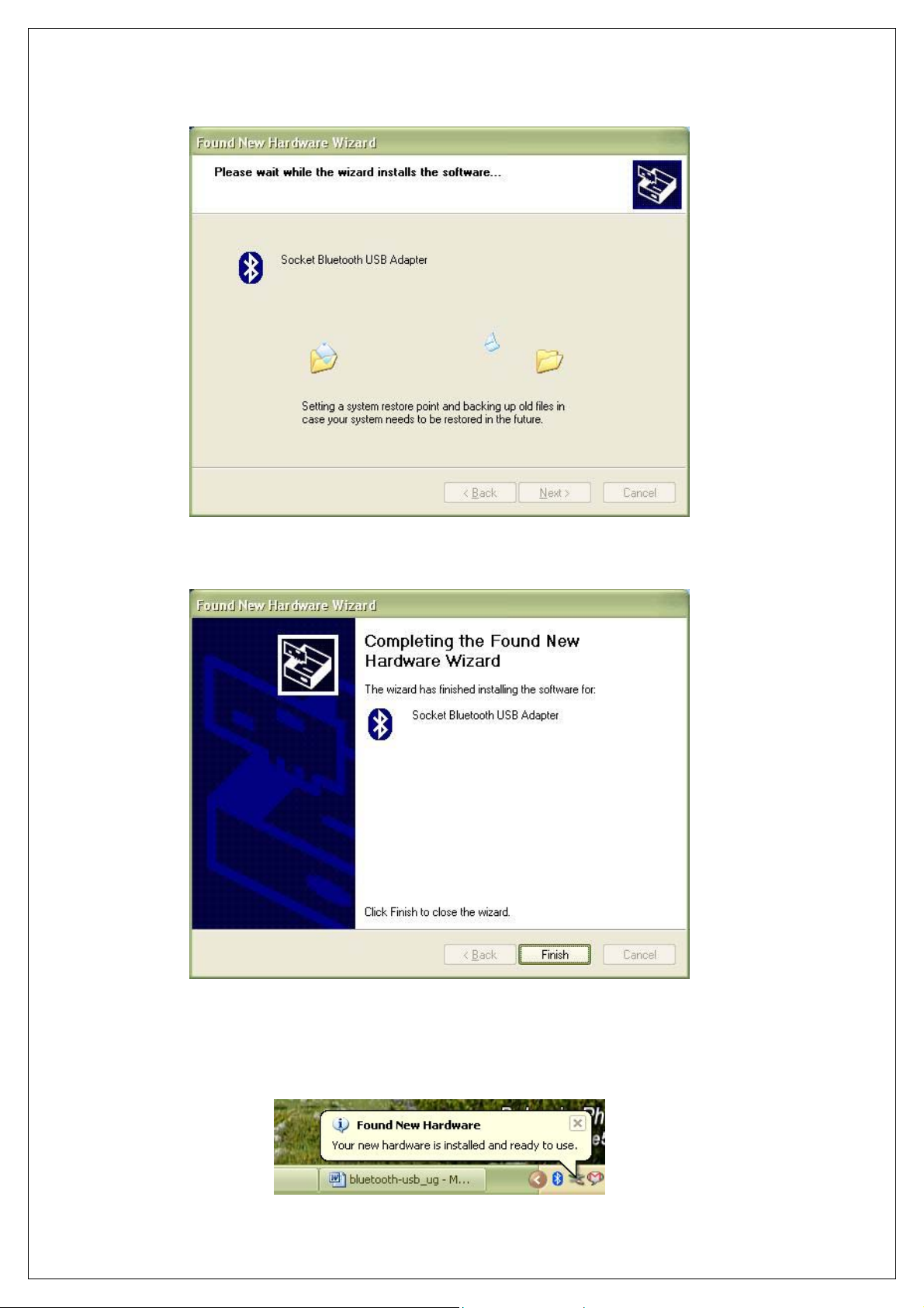
3. After the wizard finds the software, it will begin installing.
4. In the last screen click Finish.
5. A series of notification balloons will appear in the bottom right of
your screen. The last one should report that the new hardware is
installed and ready to use.
CHAPTER 2: HARDWARE AND SOFTWARE INSTALLATION 11
Page 12

6. After software installation, a Bluetooth icon may appear
in the bottom right corner, depending on your task tray.
12
Page 13

3 | MANUAL BLUETOOTH
CONNECTIONS
This chapter explains how to manually connect Scanning
Companion to the Cordless Hand Scanner (CHS) Series 7 or the
Cordless Ring Scanner (CRS) Series 9 using the Microsoft Bluetooth
utility built into Windows XP.
If you would like automatic Bluetooth connections using Socket
Mobile Connect!Agent software, please refer to Chapter 4.
If you would like to pair and connect using Socket Mobile
ActivePairing, please refer to Chapter 5.
SETUP SUMMARY
STEP 1: Turn on the CHS/CRS.
STEP 2: Add the CHS/CRS to the Microsoft Bluetooth utility.
STEP 3: Start SocketScan.
STEP 4: Configure scanner settings.
STEP 5: Restart SocketScan.
STEP 6: Connect to CHS/CRS.
CHAPTER 3: MANUAL BLUETOOTH CONNECTIONS 13
Page 14

STEP 1: TURN ON THE CHS/CRS
Turn on the CHS/CRS. Make sure it has sufficient battery power. Refer
to your CHS/CRS documentation for instructions.
STEP 2: ADD CHS/CRS TO MICROSOFT BLUETOOTH
UTILITY
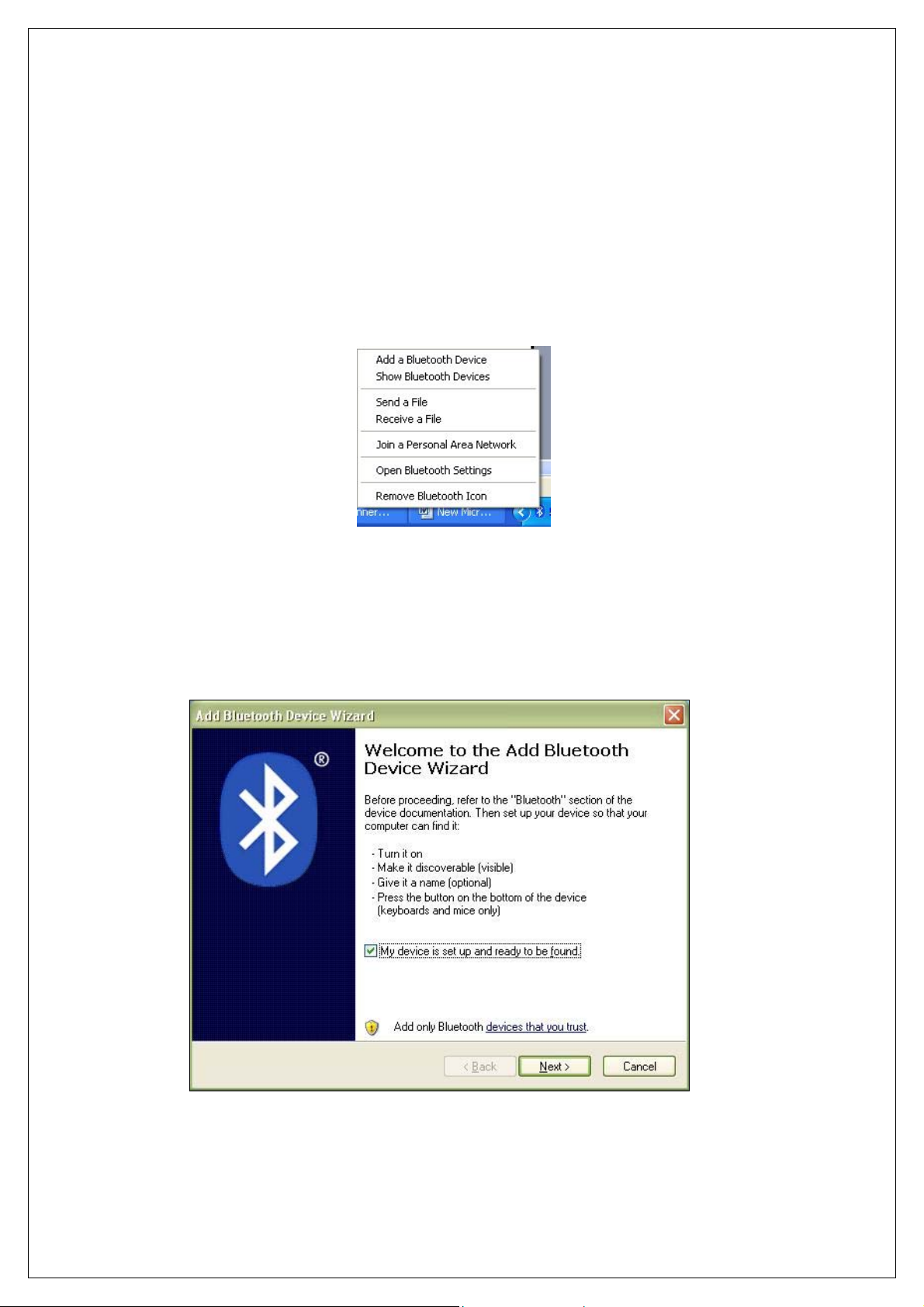
1. Use the Add Bluetooth Device Wizard to discover and connect to
the CHS/CRS. Click on the Bluetooth icon in the task tray. In the
pop-up menu, click Add a Bluetooth Device.
Note: If the Bluetooth icon does not appear, click Start | Control Panel |
Bluetooth Devices. In the Bluetooth Devices utility, click Add.
2. The Add Bluetooth Device Wizard will launch. Check the box My
device is set up and ready to be found. Click Next.
3. Your computer will search for Bluetooth devices in range.
14
Page 15
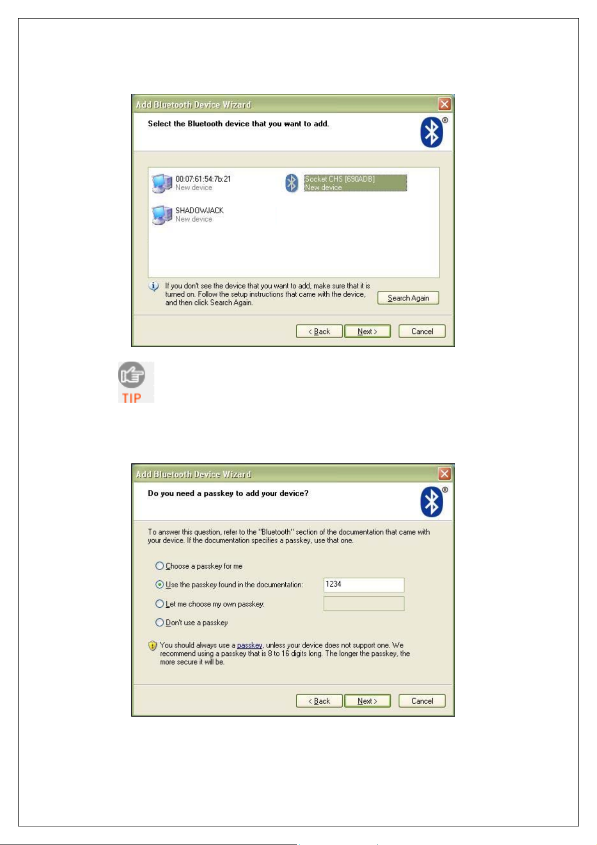
4. During the device search, select Socket CHS [xxxxxx] or
Socket CRS [xxxxxx]. Click Next.
The characters in brackets are the last 6 characters
of the scanner’s Bluetooth MAC address.
5. In the next screen, select Use the passkey found in the
documentation. Enter the default passkey
1234. Click Next.
CHAPTER 3: MANUAL BLUETOOTH CONNECTIONS 15
Page 16

6. Your computer will connect to the CHS/CRS.
7. The last screen will report the COM port numbers. Remember the
Outgoing
COM port number.
Click Finish.
Note: If you forget the COM port number, click:
Start | Control Panel | Bluetooth Devices | COM Ports.
16
Page 17

STEP 3: START SOCKETSCAN
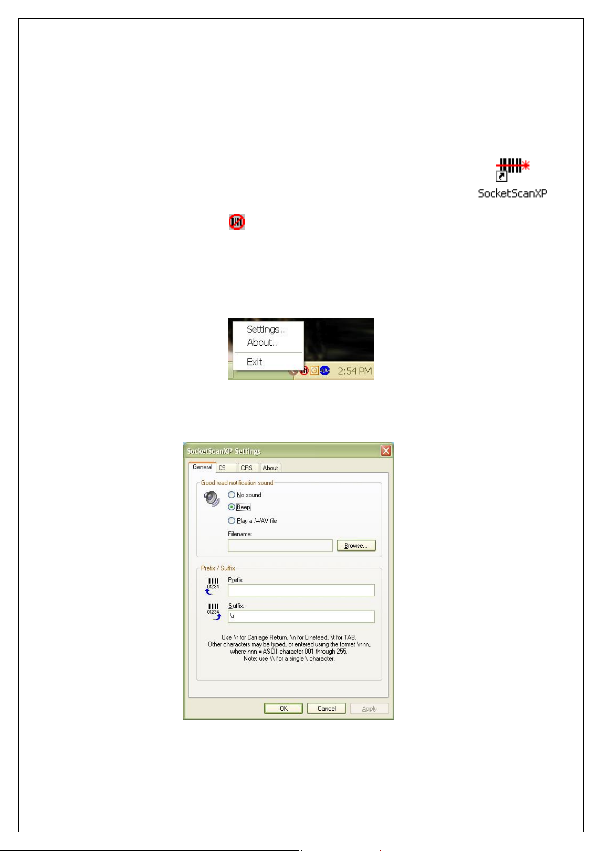
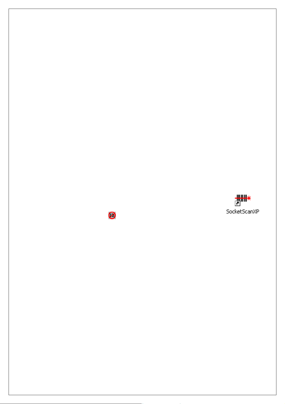
1. Start SocketScan. Double-click on the SocketScanXP icon on your
desktop.
2. The SocketScan icon
will appear at the bottom of your screen.
STEP 4: CONFIGURE SCANNER SETTINGS
1. Click on the SocketScan icon. In the pop-up menu, click Settings.
Alternatively, click Start | Control Panel | SocketScanXP Settings.
2. The SocketScanXP Settings utility will appear. Click on the CS tab.
CHAPTER 3: MANUAL BLUETOOTH CONNECTIONS 17
Page 18

3. Enter the following settings:
• Enable CS support: Check this box. IMPORTANT!!!
• Enable ActivePairing: Uncheck.
• Bluetooth stack: Select Microsoft SP2.
• COM Port: Select the Standard Serial over Bluetooth link
with the Outgoing COM port number reported by the Add New
Bluetooth Device Wizard.
• CS trigger operation: Select whether you want the CHS/CRS
to scan only when a Bluetooth connection to the device is
detected. If you select Scan only when connected to host,
scanning will be a few milliseconds slower (Error Proof Protocol
will be enabled).
• Good read indication on CS: Select how you would like the
CHS/CRS to indicate that it has successfully read data.
18
Page 19

• Auto re-connect: Select the maximum number of tries and
time limit for the CHS/CRS to try to reconnect to your computer
in case they move out of range.
• Battery Level: No progress bar should appear since you are
not connected to the CHS/CRS.
• Power management: By default, the CHS/CRS automatically
shuts off if there is no Bluetooth connection for 20 minutes.
Check to disable.
• Advanced: When the computer is connected to the CHS/CRS,
you can modify the Bluetooth friendly name and security
settings of the CHS/CRS. For more information, please refer to
the CHS/CRS documentation.
4. After entering settings, click OK to sav e the changes.
5. If SocketScan is open, you will be prompted to exit and restart
SocketScan. Click OK. Click on the SocketScan icon at the bottom
of your screen and in the pop-up menu, click Exit.
STEP 5: RESTART SOCKETSCAN
1. Start SocketScan. Double-click on the SocketScanXP icon on your
desktop.
2. The SocketScan icon
screen.
will appear at the bottom of your
CHAPTER 3: MANUAL BLUETOOTH CONNECTIONS 19
Page 20

STEP 6: CONNECT TO CHS/CRS
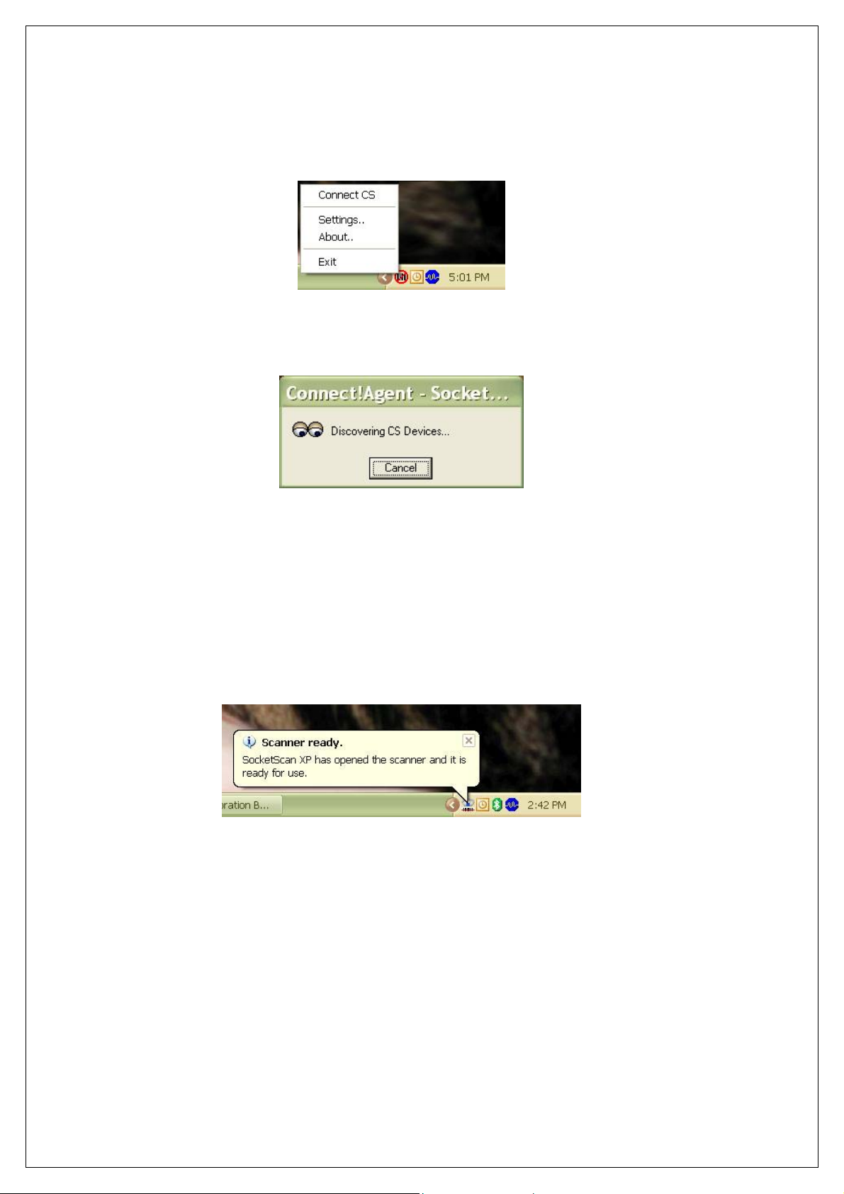
1. Right-click the SocketScan icon at the bottom of the screen and
click Connect CS.
2. A balloon will appear reporting that a Bluetooth device wants to
connect to your computer. Click on the balloon.
3. When prompted, enter the passkey 1234. Complete the rest of the
wizard to connect.
After you configure the correct Bluetooth hardware settings in
SocketScan, the Connect CS menu option allows you to connect
to the CHS directly from SocketScan, instead of manually
connecting with the Microsoft Bluetooth utility.
The Connect CS option will not appear unless you selected
Enable CS Support in the SocketScan settings. See page 18.
20
Page 21

SocketScan will not be able to connect if you have another device
assigned as your favorite or default Bluetooth serial device.
4. Your computer will connect to the CHS/CRS, indicated by a beep
and a notification balloon.
5. The task tray icon at the bottom of your screen will change to an
image of the CHS or CRS to indicate that SocketScan has
connected.
Now you are ready to begin scanning bar code data into your
Windows XP computer. Please refer to your CHS/CRS
documentation for instructions.
SocketScan Icon Meaning
No scanner connected.
Cordless Hand Scanner connected.
Cordless Ring Scanner connected.
CHAPTER 3: MANUAL BLUETOOTH CONNECTIONS 21
Page 22

AUTO-RECONNECT
If your computer suspends or the CHS/CRS turns off or moves out of
range, the connection will be lost. After the computer turns on again
or the CHS/CRS turns on again or returns to range, SocketScan will
try to reconnect according to the auto reconnect settings you chose in
SocketScan.
After the time limit for reconnection attempts has passed, you can
click on the Socket CS Connect icon on the desktop to manually
initiate reconnection.
DISCONNECTING
To disconnect, click on the scanner icon and click Disconnect CS.
22
Page 23
4 | CONNECT!AGENT
This chapter explains how to use Connect!Agent to connect
Scanning Companion to the Cordless Hand Scanner (CHS) Series 7
or the Cordless Ring Scanner (CRS) Series 9.
In order to use Connect!Agent, you must install it on your computer.
Refer to your CHS/CRS docume nta tion for more information.
SETUP SUMMARY
STEP 1: Turn on the CHS/CRS.
STEP 2: Start SocketScan.
STEP 3: Configure scanner settings.
STEP 4: Restart SocketScan.
STEP 5: Connect to CHS/CRS.
CHAPTER 4: CONNECT!AGENT 23
Page 24
STEP 1: TURN ON THE CHS/CRS
Turn on the CHS/CRS. Make sure it has sufficient battery power. Refer
to your CHS/CRS documentation for instructions.
STEP 2: START SOCKETSCAN
1. Start SocketScan. Double-click on the SocketScanXP icon on your
desktop.
2. The SocketScan icon
will appear at the bottom of your screen.
STEP 3: CONFIGURE SCANNER SETTINGS
1. Click on the SocketScan icon. In the pop-up menu, click Settings.
Alternatively, click Start | Control Panel | SocketScanXP Settings.
2. The SocketScanXP Settings utility will appear. Click on the CS tab.
24
Page 25

3. Enter the following settings:
• Enable CS support: Check this box. IMPORTANT!!!
• Enable ActivePairing: Uncheck.
• Bluetooth stack: Select Socket Connect!Agent.
• CS trigger operation: Select whether you want the CHS/CRS
to scan only when a Bluetooth connection to the device is
detected. If you select Scan only when connected to host,
scanning will be a few milliseconds slower (Error Proof Protocol
will be enabled).
• Good read indication on CS: Select how you would like the
CHS/CRS to indicate that it has successfully read data.
• Auto re-connect: Select the maximum number of tries and
time limit for the CHS/CRS to try to reconnect to your computer
in case they move out of range.
CHAPTER 4: CONNECT!AGENT 25
Page 26
• Battery Level: No progress bar should appear since you are
not connected to the CHS/CRS.
• Power management: By default, the CHS/CRS automatically
shuts off if there is no Bluetooth connection for 20 minutes.
Check to disable.
• Advanced: When the computer is connected to the CHS/CRS,
you can modify the Bluetooth friendly name and security
settings of the CHS/CRS. For more information, please refer to
the CHS/CRS documentation
4. After entering settings, click OK to sav e the changes.
5. If SocketScan is open, you will be prompted to exit and restart
SocketScan. Click OK. Click on the SocketScan icon at the bottom
of your screen and in the pop-up menu, click Exit.
STEP 4: RESTART SOCKETSCAN
1. Start SocketScan. Double-click on the SocketScanXP icon on your
desktop.
2. The SocketScan icon
screen.
will appear at the bottom of your
26
Page 27
STEP 5: CONNECT TO CHS/CRS
1. Right-click the SocketScan icon at the bottom of the screen and
click Connect CS.
2. If this is your first time connecting, Connect!Agent will
automatically search for the CHS/CRS and configure the
connection.
The Connect CS option will not appear unless you selected Enable
CS Support in the SocketScanXP settings. See page 25.
SocketScan will not be able to connect if you have another device
assigned as your favorite or default Bluetooth serial device.
3. Your computer will connect to the CHS/CRS, indicated by a beep
and a notification balloon.
4. The task tray icon at the bottom of your screen will change to an
image of the CHS or CRS to indicate that SocketScan has
connected.
Now you are ready to begin scanning bar code data into your
Windows XP computer. Please refer to your CHS/CRS
documentation for instructions.
CHAPTER 4: CONNECT!AGENT 27
Page 28

SocketScan Icon Meaning
No scanner connected.
Cordless Hand Scanner connected.
Cordless Ring Scanner connected.
AUTO-RECONNECT
If your computer suspends or the CHS/CRS turns off or moves out of
range, the connection will be lost. After the computer turns on again
or the CHS/CRS turns on again or returns to range, SocketScan will
try to reconnect according to the auto reconnect settings you chose in
SocketScan.
After the time limit for reconnection attempts has passed, you can
click on the Socket CS Connect icon on the desktop to manually
initiate reconnection.
DISCONNECTING
To disconnect, click on the scanner icon and click Disconnect CS.
28
Page 29
5 | ACTIVEPAIRING
This chapter explains how to use ActivePairing to pair and connect
Scanning Companion to the Cordless Ring Scanner (CRS) Series 9.
Scanning Companion comes with ActivePairing bar code labels for
easy deployment.
ActivePairing enables CRS Series 9 scanners to connect to a
Windows XP host computer without requiring the host computer to
initiate the connection. With ActivePairing, the CRS can pair/ unpair
with a computer by simply scanning a special bar code.
• Enabling ActivePairing mode will set the CRS in an “initiator”
mode. In initiator mode, the CRS can pair/unpair with a host
computer by scanning a special bar code.
• By not enabling ActivePairing mode, the CRS is in its current
default state of “acceptor” mode.
• If ActivePairing is enabled, the user can return the CRS to
normal “acceptor” mode by scanning a special bar code.
Notes: Only the latest revisions of the wireless wrist module support
ActivePairing. Check the label on the back of the wrist module for the
part number revision letter.
CRS
Version
Part Number Revisions with Active Pairing
Support
9M 9010-00730 “F” or later
9P 9010-00703 “F” or later
ActivePairing Bar Code Labels
CHAPTER 5: ACTIVEPAIRING 29
Page 30

Scanning Companion comes with a set of ActivePairing bar code
labels. For instructions on how to print more labels, please refer to
the CRS documentation.
SETUP SUMMARY
STEP 1: Turn on the CRS.
STEP 2: Add the CRS to the Microsoft Bluetooth utility.
STEP 3: Start SocketScan.
STEP 4: Configure scanner settings.
STEP 5: Restart SocketScan.
STEP 6: Stick ActivePairing Bar Code Labels onto Computer
STEP 7: Scan the Initiator Bar Code.
STEP 8: Enter the Passkey
30
Page 31
STEP 1: TURN ON THE CRS
Turn on the CRS. Make sure it has sufficient battery power. Refer to your
CRS documentation for instructions.
STEP 2: ADD CRS TO MICROSOFT BLUETOOTH UTILITY
1. Use the Add Bluetooth Device Wizard to discover and connect to
the CRS. Click on the Bluetooth icon in the task tray. In the popup menu, click Add a Bluetooth Device.
Note: If the Bluetooth icon does not appear, click Start | Control Panel |
Bluetooth Devices. In the Bluetooth Devices utility, click Add.
2. The Add Bluetooth Device Wizard will launch. Check the box My
device is set up and ready to be found. Click Next.
3. Your computer will search for Bluetooth devices in range.
CHAPTER 5: ACTIVEPAIRING 31
Page 32

4. During the device search, select Socket CRS [xxxxxx]. Click
Next.
The characters in brackets are the last 6 characters
of the scanner’s Bluetooth MAC address.
5. In the next screen, select Use the passkey found in the
documentation. Enter the default passkey
1234. Click Next.
32
Page 33

6. Your computer will connect to the CRS.
7. A series of notification balloons will appear.
8. In the last screen, remember the Incoming
Click Finish.
COM port number.
Note: If you forget the COM port number, click:
Start | Control Panel | Bluetooth Devices | COM Ports.
CHAPTER 5: ACTIVEPAIRING 33
Page 34

STEP 3: START SOCKETSCAN
1. Start SocketScan. Double-click on the SocketScanXP icon on your
desktop.
2. The SocketScan icon
will appear at the bottom of your screen.
STEP 4: CONFIGURE SCANNER SETTINGS
1. Click on the SocketScan icon. In the pop-up menu, click Settings.
Alternatively, click Start | Control Panel | SocketScanXP Settings.
2. The SocketScanXP Settings utility will appear. Click on the CS tab.
3. Enter the following settings:
34
Page 35

• Enable CS support: Check this box. IMPORTANT!!!
• Enable ActivePairing: Check this box. IMPORTANT!!!
• Bluetooth stack: Select Microsoft SP2.
• COM Port: Select the Standard Serial over Bluetooth link
with the Incoming COM port number reported by the Add New
Bluetooth Device Wizard.
• CS trigger operation: Select whether you want the CRS to
scan only when a Bluetooth connection to the device is
detected. If you select Scan only when connected to host,
scanning will be a few milliseconds slower (Error Proof Protocol
will be enabled).
• Good read indication on CS: Select how you would like the
CRS to indicate that it has successfully read data.
CHAPTER 5: ACTIVEPAIRING 35
Page 36

• Auto re-connect: Select the maximum number of tries and
time limit for the CRS to try to reconnect to your computer in
case they move out of range.
• Battery Level: No progress bar should appear since you are
not connected to the CRS.
• Power management: By default, the CRS automatically shuts
off if there is no Bluetooth connection for 20 minutes. Check to
disable.
• Advanced: When the computer is connected to the CRS, you
can modify the Bluetooth friendly name and security settings of
the CRS. For more information, please refer to the CHS/CRS
documentation.
4. After entering settings, click OK to sav e the changes.
5. If SocketScan is open, you will be prompted to exit and restart
SocketScan. Click OK. Click on the SocketScan icon at the bottom
of your screen and in the pop-up menu, click Exit.
STEP 5: RESTART SOCKETSCAN
1. Start SocketScan. Double-click on the SocketScanXP icon on your
desktop.
2. The SocketScan icon
screen.
will appear at the bottom of your
STEP 6: STICK ACTIVEPAIRING BAR CODES ONTO
COMPUTER
If desired, stick the included Active Pairing bar code labels to the
computer that you plan to use Scanning Companion with.
STEP 7: SCAN INITIATOR BAR CODE
Scan the “Initiator” bar code, which is the FNI bar code at the top of
the included label.
36
Page 37

STEP 8: ENTER PASSKEY
1. Within 10 seconds after scanning the Initiator bar code, you will
be prompted to enter a passkey. Enter the passkey
1234.
2. Your computer will connect to the CHS/CRS, indicated by a beep
and a notification balloon.
3. The task tray icon at the bottom of your screen will change to an
image of the CRS to indicate that SocketScan has connected.
SocketScan Icon Meaning
No scanner connected.
Cordless Ring Scanner connected.
Note:
• It may take several seconds for the CRS to pair and connect.
• SocketScan will not be able to connect if you have set another
device as your favorite or default Bluetooth serial device.
4. Now you are ready to begin scanning bar code data into your
Windows XP computer. Please refer to your CRS documentation
for instructions.
CHAPTER 5: ACTIVEPAIRING 37
Page 38

PAIRING AND CONNECTING TO ANOTHER COMPUTER
1. Scan the “Acceptor” bar code, (the FNA bar code on the bottom of the
included label) to disconnect from the first host computer.
2. Move within Bluetooth range of the second host computer.
3. Scan the “Initiator” bar code associated with the second host
computer.
4. Within 10 seconds, you will be prompted to enter a passkey. Enter the
passkey
1234.
AUTO-RECONNECT
If your computer suspends or the CHS/CRS turns off or moves out of
range, the connection will be lost. After the computer turns on again
or the CHS/CRS turns on again or returns to range, SocketScan will
try to reconnect according to the auto reconnect settings you chose in
SocketScan.
After the time limit for reconnection attempts has passed, you can
click on the Socket CS Connect icon on the desktop to manually
initiate reconnection.
DISCONNECTING
To disconnect, do the following:
1. Unpair the CRS from Scanning Companion by scanning the #FNA#
bar code.
2. Turn off the CRS.
IMPORTANT! Do not try to disconnect by simply clicking
“Disconnect” in the SocketScan menu, or the CRS can hang.
38
Page 39

APPENDIX A
PECIFICATIONS
S
Physical Characteristics
Size: 69 x 20 x 8.6 mm (2.7 x 0.79 x 0.34 in.)
Total Mass: 11 g (0.39 oz)
Interface: USB 2.0
LED: Power (blue)
Environmental Characteristics:
Operating Temp: 32 to 113°F (0 to 45°C)
Storage Temp: -4 to +113°F (-20 to +45°C) ambient
Operating/Storage Humidity: 90% maximum non-condensing
Bluetooth Characteristics
Protocol: Bluetooth 2.0 + EDR (Enhanced Data Rate)
Chipset: CSR BC04-EXT
Antenna: Integrated into the adapter housing
Radio Range: Class 1 Bluetooth - up to 330 ft (100 m), depending on
environment and CHS/CRS version
Sensitivity: -77 dBm typical
Frequency Range: 2.45 GHz ISM band, FHSS
Selectable Channels: 79
Topology: Point-to-point and point to multipoint
Power Consumption: 5 VDC, 200 mA maximum (normal operation)
Output Power: 16 dBm maximum
Security: Data encryption up to 128 bits
Hardware and Software Compatibility:
Hardware: Notebook, tablet and desktop computers running
Windows XP/XP Tablet Edition
Software: Microsoft Bluetooth stack, SocketScan, Connect!Agent
Certification/Compliance
FCC: Part 15, Class B
CE: EN55024:2003, EN300328, EN300826, RoHS
A-Tick s.182
Bluetooth 2.0 +EDR
Microsoft WHQL
APPENDIX A: SPECIFICATIONS 39
Page 40

About Bluetooth Range
Scanning Companion features a powerful Class 1 Bluetooth radio to
provide the maximum possible range. As with all wireless
technologies, the connection range can vary widely depending on
many factors such as the placement of the peripheral devices, the
type and size of physical obstacles and the presence and activity
level of competing radio transmissions.
The following conditions appear to reduce the Bluetooth connection
range:
• The presence of soft, absorbent materials such as paper,
fiberglass insulation, foam material in office cubical walls,
carpeting and, to a lesser extent, even sheetrock and wood
construction materials. Hard materials such as concrete incr ease
the range.
• Human bodies or containers of liquid positioned between
Scanning Companion and the CHS/CRS.
• The presence and activity level of competing Bluetooth or 802.11
(Wi-Fi) systems using the same 2.4 GHz frequency.
• Metal in a grid pattern, such as chain link fencing or chicken wire.
This type of material may block the Bluetooth (or Wi-Fi) signal
completely.
• The device at the other end
40 | APPENDIX A: SPECIFICATIONS
Page 41

APPENDIX B
AFETY AND USAGE TIPS
S
About Bluetooth and Health
Bluetooth wireless technology allows you to use short-range radio
signals to connect a variety of devices, such as bar code scanners,
mobile phones, Pocket PCs, notebook computers, printers, LAN
access points, and many other devices at home or work. These radio
signals replace the cables that have traditionally connected these
devices.
Class I Bluetooth products have small radio transmitters and
receivers. Output power is normally very low, and for Scanning
Companion, the maximum is only 16 dBm. This gives a working
range of approximately 100 meters (328 feet).
The maximum exposure levels from Bluetooth products are far below
recommended safety guidelines. At most, typical Bluetooth devices
(1 mW) reach only one percent of the prescribed safety levels.
Product Care
• Do not expose your product to liquid, moisture or extreme
humidity.
• Do not expose your product to extreme high or low temperatures.
• Do not expose your product to lit candles, cigarettes, or cigars, or
to open flames, etc.
• Do not drop, throw or try to bend the product, as rough treatment
could damage it.
• Do not paint your product, as the paint could obstruct parts and
prevent normal use.
• Do not attempt to disassemble your product: a broken warranty
seal will void the warranty. The product does not contain
consumer serviceable components. Should your Scanning
Companion need service, contact Socket Mobile technical
support at: www.socketmobile.com/support/support/
• Treat your product with care. Keep in a clean and dust-free place.
• Changes or modifications of this product, not expressly approved
by Socket Mobile, may void the user’s authority to operate the
equipment.
Antenna Care
Do not place a metallic shield around Scanning Companion since it
will reduce the radio transmission efficiency.
.
APPENDIX B: SAFETY AND USAGE TIPS 41
Page 42

Efficient Use
For optimum performance, please make sure that there is no metal
surrounding your Scanning Companion.
Driving
RF energy may affect some electronic systems in motor vehicles,
such as car stereo, safety equipment, etc. Check with your vehicle
manufacturer to be sure that Scanning Companion will not affect the
vehicle’s electronics.
Aircraft
• Turn off Scanning Companion before boarding any aircraft.
• To prevent interference with communications system s, you must
not use Scanning Companion while the plane is in the air.
• Do not use it on the ground without permission from the crew.
Radio Frequency Exposure
Scanning Companion contains a radio transmitter and receiver.
When in operation, it communicates with the Cordless Hand Scanner
or Cordless Ring Scanner by receiving and transmitting radio
frequency (RF) magnetic fields in the frequency range 2400 to 2500
MHz. The maximum output power of the radio transmitter is 16 dBm.
Scanning Companion is designed to be in compliance with the RF
exposure limits set by national authorities and international health
agencies
1
when installed or used separately from other antennas or
radio transmitters.
1
Examples of RF exposure standards and guidelines:
ICNIRP, “Guidelines for limiting exposure to time-varying electric, magnetic, and
electromagnetic fields (up to 300 GHz)”, International Commission on NonIonizing Radiation Protection (ICNIRP), Health Physics, vol. 74, pp 494-533, April
1998.
99/519/EC, EU Council Recommendation on the limitation of exposure to the
general public to electromagnetic fields 0 Hz – 300 GHz, Official Journal of the
European Communities, July 12, 1999.
ANSI/IEEE C95.1-1992, “Safety levels wit h respect to human exposure to radio
frequency electromagnetic fields, 3 kHz to 300 GHz”, The Institute of Electrical and
Electronics Engineers, Inc., New York, 1991.
FCC Report and Order, ET Docket 93-62, FCC 96-326, Federal Communications
Commission (FCC), August 1996.
Radiocommunications (Electromagnetic Radiation Human Exposure) Standard 1999,
Australian Communications Aut hority (ACA), May 1999.
42
Page 43
APPENDIX C
ECHNICAL SUPPORT
T
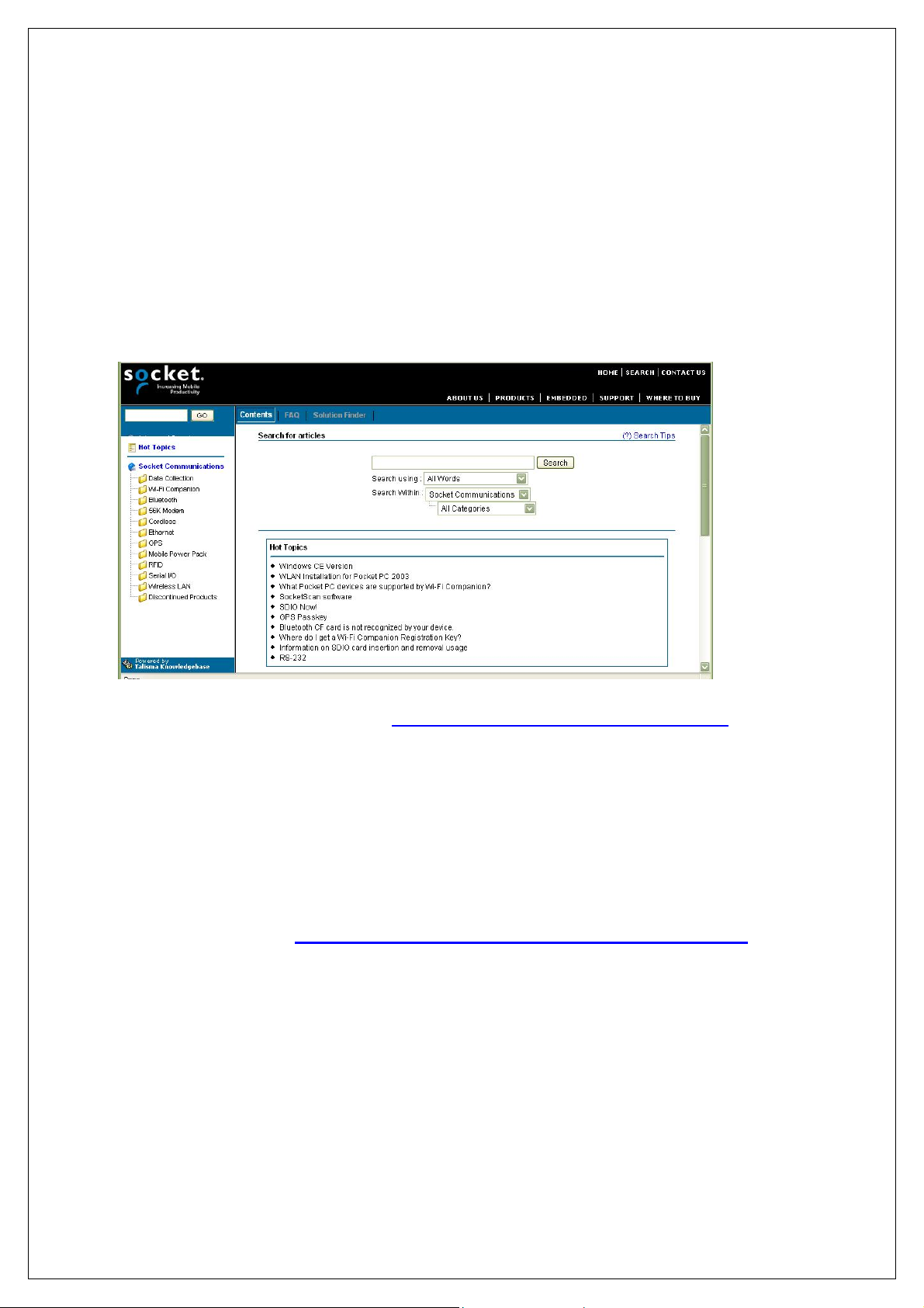
Socket On-Line Support (SOS)
SOS is a virtual technical support assistant that can help you with
your product support questions or FAQs. SOS responds immediately
to your inquiry, and no product registration is required to use the
system.
To access SOS, please visit: www.socketmobile.com/support/faq/
Live Technical Support
If you have trouble installing or using Scanning Companion, contact
the Socket Mobile technical support department for assistance.
IMPORTANT! To obtain technical support, first register your
product online at www.socketmobile.com/support/support/new
After you register your product, log in and click on the Technical
Support tab. Click Create New Ticket to submit an online request
for technical support. Afterwards, you can log in anytime to monitor
the status of your request. If we are unable to resolve your support
inquiry online, we can arrange for a technical support representative
to call you at a specific time.
.
APPENDIX E: TECHNICAL SUPPORT | 43
Page 44

LIMITED WARRANTY
Socket Communications Incorporated (Socket ) warrants this product against
defects in material and workmanship, under normal use and service, for one
(1) year from the date of purchase.
EXCLUDES: Consumables such as batteries, removable cables, cases,
straps, chargers, and CF-to-PC Card adapters (90 day coverage only)
An extended warranty is available separately for the Cordless Hand Scanner
or Cordless Ring Scanner. For more information, please visit:
www.socketmobile.com/support
Incompatibility is not a defect covered by Socket’s warranty. During the
warranty period, Socket will, at its option, repair or replace the defective
product at no charge when furnished with proof of retail purchase, provided
that you deliver the product to Socket or t o an authorized Socket Service
Center.
The returned product must be accompanied by a return material
authorization (RMA) number issued by Socket or by Socket's Authorized
Service Center. If you ship the product , you must use the original container
or equivalent and you must pay the shipping charges to Socket. Socket will
pay surface shipping charges back to any location in the contiguous United
States. This warranty applies only to the original retail purchaser and is not
transferable.
Socket may, at its option, replac e or repair the product with new or
reconditioned parts and the returned produc t becomes Socket's property.
Socket warrants the repaired or replaced products to be fr ee from defects in
material or workmanship for ninety (90) days after the return shipping date,
or for the remainder of the original warranty period, whichever is greater.
This warranty does not cover the replacement of products damaged by
abuse, accident, misuse or misapplication, nor as a result of service or
modification other than by Socket. This warranty is void if you install batteries
into the product that were not supplied by Socket.
SOCKET IS NOT RESPONSIBLE FOR INCIDENTAL OR
CONSEQUENTIAL DAMAGES RESULTING FROM BREACH OF ANY
EXPRESS OR IMPLIED WARRANTY, INCLUDING DAMAGE TO
PROPERTY AND, TO THE EXTENT PERMITTED BY LAW, DAMAGES
FOR PERSONAL INJURY. THIS WARRANTY IS IN LIEU OF ALL OTHER
WARRANTIES INCLUDING IMPLIED WARRANTIES OF
MERCHANTABILITY AND FITNES S FOR A PARTICULAR PURPOSE.
Some states do not allow limitation of implied warranties, or the exclusion or
limitation of incidental or consequential damages, so that the above
limitations or exclusions may not apply to you. This warranty gives you
specific legal rights and you may also have other rights which vary from state
to state.
44
Page 45

This product may contain fully tested, recycled parts, warranted as if new.
For warranty information, please visit: www.socketmobile.com/support
45
Page 46

LIMITED SOFTWARE WARRANTY
LIMITED WARRANTY. SOCKET warrants that the original disk or CD ROM
is free from defects for 90 days from the date of delivery of the SOFTWARE.
CUSTOMER REMEDIES. SOCKET’S entire liability and your exclusive
remedy shall be, at SOCKET’S option, either (a) return of the price paid or (b)
replacement of the SOFTWARE which does not meet SOCKET’S Limited
Warranty and which is returned to SOCKET with a copy of your receipt. Any
replacement SOFTWARE will be warranted for the remainder of the original
warranty period or 30 days, whichever is longer. THESE REMEDIES ARE
NOT AVAILABLE OUTSIDE OF THE UNITED STATES OF AMERICA.
NO OTHER WARRANTIES. SOCKET disclaims all other warranties, either
express or implied, including but not limited to implied warranties of
merchantability and fitness for a particular purpose, with respect to the
SOFTWARE and the accompanying written materials. This limited warranty
gives you specific legal rights. You may have others which vary from state to
state.
NO LIABILITY FOR CONSEQUENTIAL DAMAGES. In no event shall
SOCKET or its suppliers be liable for any damages whatsoever (including,
without limitation, damages for loss of business profits, business interruption,
loss of business information, or other pecuniary loss) arising out of the use of
or inability to use the SOFTWARE, even if SOCKET has been advised of the
possibility of such damages. Because some states do not allow the exclusion
or limitation of liability for consequential or incidental damages, the above
limitation may not apply to you.
EXPORT LAW ASSURANCES. You may not us e or otherwise export or
reexport the SOFTWARE except as authorized by United States law and
laws of the jurisdiction in which the SOFTWARE was obtained. In particular,
but without limitation, none of the SOFTWARE may be used or otherwise
exported or reexported (a) into (or to a national or resident of) a United
States embargoed country or (b) to anyone on the U.S. Treasury
Department’s list of Specially Designated Nationals or the U.S. Department
of Commerce’s Table of Denial O rders. By using the SOFTWARE, you
represent and warrant that you are not located in, under control of , or a
national or resident of any such country or on any such list.
GOVERNMENT END USERS. If the SOFTWARE is supplied to the U. S.
Government, the SOFTW ARE is classified as “restrict ed computer software”
as defined in clause 52.227-19 of the FAR. The U. S. Government ‘s rights
to the SOFTWARE are as provided in clause 52.227-19 of the FAR.
CONTROLLING LAW AND SEVERABILI TY. This License shall be
governed by the laws of the United States and the State of California.
If for any reason a court of competent jurisdiction finds any provision,
46
Page 47

or portion thereof, to be unenforceable, the remainder of this License
shall continue in full force and effect.
47
Page 48

REGULATORY COMPLIANCE
The Socket Mobile Scanning Companion is designed to be compliant
with the rules and regulations in locations where they are sold and
will be labeled as required. This product is type approved — users
are not required to obtain license or authorization before using.
This product has been certified as conforming to technological
standards. Therefore, the following actions are punishable by law:
• Disassembly or modification of this product
• Removal of identification labels on the back of the product
The frequency used by this product is also used by industrial,
scientific and medical devices, such as microwave ovens, as well as
wireless detectors for motion detectors, such as those requiring
licenses used on manufacturing lines or similar radio transmitters (all
of these wireless devices will be called “other wireless transmitters”
below). Most modern electronic equipment (e.g., in hospitals and
cars), is shielded from RF energy. However, certain electronic
equipment is not.
1. Please ensure that all medical devices used in proximity to this
device meet appropriate susceptibility specifications for this type
of RF energy.
2. In the unlikely event that there is electronic interference between
this system and other wireless transmitters, quickly change the
location of operation or stop operating the unit (cease signal
transmission).
3. If other electrical interference or related problems occur, contact
Socket technical support at
www.socketmobile.com/support/support
Federal Communication Commission Interference Statement
This equipment has been tested and found to comply with the limits
for a Class B digital device, pursuant to Part 15 of the FCC Rules.
These limits are designed to provide reasonable protection against
harmful interference in a residential installation. This equipment
generates, uses and can radiate radio frequency energy and, if not
installed and used in accordance with the instructions, may cause
harmful interference to radio communications. However, there is no
guarantee that interference will not occur in a particular installation. If
this equipment does cause harmful interference to radio or television
reception, which can be determined by turning the equipment off and
on, the user is encouraged to try to correct the interference by one of
the following measures:
48
Page 49

• Reorient or relocate the receiving antenna.
• Increase the separation between the equipment and receiver.
• Connect the equipment into an outlet on a circuit different from
that to which the receiver is connected.
• Consult the dealer or an experienced radio/TV technician for help.
FCC Caution: Any changes or modifications not expressly approved
by the party responsible for compliance could void the user's
authority to operate this equipment.
This device complies with part 15 of the FCC rules. Operation is
subject to the following conditions: (1) This device may not cause
harmful interference, and (2) this device must accept any
interference received, including interference that may cause
undesired operation.
This equipment complies with FCC RF radiation exposure limits set
forth for an uncontrolled environment. To maintain compliance with
FCC RF exposure compliance requirements, please avoid direct
contact to the transmitting antenna during transmitting.
This equipment is also ETS EN300 328-2, ETS EN301 489-1 and
ETS EN301 489-17 compliant. These limits are designed to provide
reasonable protection against harmful interference when the
equipment is operated in a commercial environment.
This equipment generates and radiates radio-frequency energy. To
comply with FCC RF exposure compliance requirements, the
following antenna installation and device operating configurations
must be satisfied: (1) Users are not permitted to make changes or
modify the system in any way, and (2) connecting external antennas
to the Scanning Companion is prohibited. This device and its
antenna must not be co-located or operated with any other antenna
or transmitter.
To comply with Industry Canada RF exposure compliance
requirements, the following antenna installation and device operating
configurations must be satisfied: “The installer of this radio equipment
must ensure that the antenna is located or pointed such that it does
not emit RF field in excess of Health Canada limits for the general
population; consult Safety Code 6, available at Health Canada’s
website www.hc-sc.gc.ca/ehp/ehd/catalogue/rpb.htm
If this equipment does cause harmful interference to radio or
television reception, which can be determined by turning the
”
49
Page 50

equipment off and on, the user may try to correct the interference by
one or more of the following measures:
• Reorient or relocate the receiving antenna of the radio or
television.
• Increase the distance separating the equipment and the receiver.
• Connect the equipment to an outlet on a different branch circuit
than that of the receiver.
• Consult the dealer or an experienced radio/TV technician for help.
The user may find the following booklet helpful: How to Identify and
Resolve Radio-TV Interference Problems. This booklet is available
from the U.S. Government Printing Office, Washington, D.C. 20402.
NOTE: To comply with FCC and Industry Canada exposure
requirements, this device is approved for operations in a user’s hand
when there is a distance of 20 cm or more between the device
antenna and the user’s body.
Industry Canada Statement
This device complies with RSS-210 of the Industry Canada Rules.
Operation is subject to the following two conditions:
1) this device may not cause interference and
2) this device must accept any interference, including interference
that may cause undesired operation of the device
IMPORTANT NOTE:
IC Radiation Exposure Statement:
This equipment complies with IC radiation exposure limits set forth
for an uncontrolled environment. End users must follow the specific
operating instructions for satisfying RF exposure compliance. To
maintain compliance with IC RF exposure compliance requirements,
please follow operation instruction as documented in this manual.
Canada Certification
The marking of “IC:2529A-USB2” on the device means: “IC:2529AUSB2” is the certification number, and the term “IC’ before the
equipment certification number only signifies that Industry Canada
technical specifications were met.
Radio Frequency Interference Requirements – Canada
This Class B digital apparatus meets the requirements of the
Canadian Interference-Causing Equipment Regulations. Cet
appareil numérique de la Classe B respecte toutes les exigencies du
Reglement sur le Matériel Brouilleur du Canada.
50
Page 51

CE Marking & European Union Compliance
Products intended for sale within the European Union are marked
with a CE Mark which indicates compliance to applicable Directives
and European Normes (EN), as follows. Amendments to these
Directives or ENs are included: Normes (EN), as follows:
Applicable Directives:
• Radio and Telecommunications Terminal Equipment Directive
1999/5/EC
• Low Voltage Directive 73/23/EEC
Applicable Standards:
• EN 55 022 – Limits and Methods of Measurement of Radio
Interference Characteristics of Information Technology Equipment.
• EN 50 082-1 – Electromagnetic Compatibility – General Immunity
Standard, Part 1: Residential, Commercial, Light Industry.
• IEC 801.2 – Electromagnetic Compatibility for Industrial Process
Measurement and Control Equipment, Part 2: Electrostatic
Discharge Requirements.
• IEC 801.3 – Electromagnetic Compatibility for Industrial Process
Measurement and Control Equipment, Part 3: Radiated
Electromagnetic Field Requirements.
• IEC 801.4 - Electromagnetic Compatibility for Industrial Process
Measurement and Control Equipment, Part 4: Electrical Fast
Transients Requirements
• EN 60 950 + Amd 1 + Amd 2 – Safety of Information Technology
Equipment Including Business Equipment.
Product Disposal
Your device should not be placed in municipal waste.
Please check local regulations for disposal of electronic
products.
51
Page 52

11/2007 Printed in U.S.A.
 Loading...