

SOARNEX EG210-28-185W, EG210-10-123W, EG210-20-185W, EG210-52-370W, EG210-52-740W User Manual
...
EG210 series
L2+ Smart
Management
Switch user
manual
Release 1.00.003

EG210 Series L2+ Smart Managed Switch
1
User Manual
Content
Change History ................................................................................................................................................... 3
Chapter 1. Intended readers ........................................................................................................................ 4
Chapter 2. Declaration ................................................................................................................................. 4
Chapter 3. Introduction ............................................................................................................................... 5
Chapter 4. Overview .................................................................................................................................... 5
1. Power over Ethernet (PoE) ................................................................................................................. 6
2. Advance PoE management function .................................................................................................. 6
3. Excellent manageability ..................................................................................................................... 6
4. Management ...................................................................................................................................... 7
1-1. Configuration the management Switch ............................................................................. 7
Chapter 5. Main Features .......................................................................................................................... 11
1. Switch Info ........................................................................................................................................ 11
1-1. Switch Info ........................................................................................................................ 11
2. System .............................................................................................................................................. 13
2-1. System Management ....................................................................................................... 13
2-2. L3 Feature ........................................................................................................................ 14
2-3. DNS ................................................................................................................................... 25
2-4. IP Access List .................................................................................................................... 26
2-5. Administration ................................................................................................................. 28
2-6. Timeout ............................................................................................................................ 29
2-7. System Time ..................................................................................................................... 30
2-8. SSL .................................................................................................................................... 33
2-9. SSH ................................................................................................................................... 33
2-10. Telnet ................................................................................................................................ 34
2-11. DHCP Auto Configuration ................................................................................................. 34
2-12. System Log ....................................................................................................................... 35
2-13. SNMP ................................................................................................................................ 37
2-14. RMON ............................................................................................................................... 45
2-15. Statistics ........................................................................................................................... 53
2-16. IEEE 802.3az EEE .............................................................................................................. 55
3. Network ........................................................................................................................................... 56
3-1. Physical Interface ............................................................................................................. 56
3-2. Spanning Tree ................................................................................................................... 61
3-3. Trunk ................................................................................................................................ 71
3-4. Mirroring .......................................................................................................................... 75
3-5. Loopback Detection ......................................................................................................... 76
3-6. Static Unicast .................................................................................................................... 77
3-7. Static Multicast................................................................................................................. 78

EG210 Series L2+ Smart Managed Switch
2
User Manual
3-8. IGMP Snooping ................................................................................................................ 79
3-9. MLD .................................................................................................................................. 82
3-10. Multicast VLAN ................................................................................................................. 86
3-11. Multicast Filter ................................................................................................................. 91
3-12. Bandwidth Control ........................................................................................................... 92
3-13. VLAN ................................................................................................................................. 94
3-14. GVRP............................................................................................................................... 101
3-15. Voice VLAN ..................................................................................................................... 103
3-16. LLDP ................................................................................................................................ 107
3-17. MAC VLAN ...................................................................................................................... 124
3-18. Protocol VLAN ................................................................................................................ 126
4. QoS ................................................................................................................................................. 128
4-1. CoS ................................................................................................................................. 128
4-2. Port Priority .................................................................................................................... 129
4-3. DSCP ............................................................................................................................... 130
4-4. Scheduling Algorithm Settings ....................................................................................... 131
4-5. IPv6 Traffic Class ............................................................................................................. 131
5. PoE ................................................................................................................................................. 132
5-1. Power over Ethernet ...................................................................................................... 133
5-2. Time Range..................................................................................................................... 136
6. Security .......................................................................................................................................... 137
6-1. Port Access Control ........................................................................................................ 137
6-2. Dial-In User ..................................................................................................................... 142
6-3. RADIUS ........................................................................................................................... 144
6-4. TACACS+ ......................................................................................................................... 146
6-5. Destination MAC Filter ................................................................................................... 148
6-6. Denial of Service ............................................................................................................ 149
6-7. DHCP Snooping .............................................................................................................. 151
6-8. Dynamic ARP Inspection ................................................................................................ 156
6-9. ACL ................................................................................................................................. 164
7. Tools ............................................................................................................................................... 183
7-1. Firmware Upgrade ......................................................................................................... 183
7-2. Configuration ................................................................................................................. 185
7-3. Diagnostics ..................................................................................................................... 187
7-4. Reboot ............................................................................................................................ 191
7-5. Ping ................................................................................................................................. 191
Chapter 6. Figures .................................................................................................................................... 194
Chapter 7. Events ..................................................................................................................................... 199
Chapter 8. Command Line Interface (CLI) ................................................................................................ 202

EG210 Series L2+ Smart Managed Switch
3
User Manual
8.1. CLI - Symbol Description ........................................................................................................ 202
8.2. CLI - Base ................................................................................................................................ 202
8.3. CLI - Config ............................................................................................................................. 203
8.4. CLI - Download/Upgrade Firmware ....................................................................................... 203
8.5. CLI - Download/Upgrade Config ............................................................................................ 203
8.6. CLI - Ping ................................................................................................................................. 204
8.7. CLI - Save, Reboot, Reset Config ............................................................................................ 204
8.8. CLI - Show ............................................................................................................................... 204
Change History
v1.00.001: Initial commercial released (2018/03/01)
Base on FW version: v1.00.005
v1.00.002: Base on FW version: v2.10.001
Added Features:
1. Dual Image
2. Dual Configuration
3. TC Root/Protect
4. MAC-Based VLAN
5. Protocol-Based VLAN
6. Multicast VLAN Registration (MVR)
7. LLDP-MED
8. MLD
9. Dynamic ARP Inspection
10. Block unknown multicast with GUI (Multicast Filter)
11. IGMP Fast leave
12. Telnet
13. SSH
14. IP MAC Port Binding
15. Support Command Line Interface (CLI)
v1.00.003: Base on FW version: v2.10.004
Added describes of the EG210-10-2F in L2+ Smart Managed Switch.
Added describes of the command-line interface (CLI).

EG210 Series L2+ Smart Managed Switch
4
User Manual
Chapter 1. Intended readers
The document is written for networking managers who are familiar with IT concepts.
This document also provides detailed information for how to use the managed Switch via Web-Based
management interface to configure and maintain the Switches.
Chapter 2. Declaration
This document is a reference for network manager administrator to configure managed Switches. The
contents in the manual, such as web page snapshot and configuration scenarios are based on the Switch
conditions in the lab environment. This manual provides few instructions for general scenarios. But, do not
cover all usage scenarios for all users environment; the network manager administrator should configure
his devices according to actual situations.

EG210 Series L2+ Smart Managed Switch
5
EG210-10-75W
8-Ports Gigabit 802.3at + 2*1000Base-T SFP ports (75Watts) Managed PoE Switch
EG210-10-123W
8-Ports Gigabit 802.3at + 2*1000Base-T SFP ports (123Watts) Managed PoE Switch
EG210-20-185W
16-Ports Gigabit 802.3at + 4*Combo 1000Base-T RJ-45/SFP ports (185Watts)
Managed PoE Switch
EG210-28-185W
24-Ports Gigabit 802.3at + 4*Combo 1000Base-T RJ-45/SFP ports (185Watts)
Managed PoE Switch
EG210-28-370W
24-Ports Gigabit 802.3at + 4*Combo 1000Base-T RJ-45/SFP ports (370Watts)
Managed PoE Switch
EG210-52-370W
48-Ports Gigabit 802.3at + 4*Combo 1000Base-T RJ-45/SFP ports (370Watts)
Managed PoE Switch
EG210-52-740W
48-Ports Gigabit 802.3at + 4*Combo 1000Base-T RJ-45/SFP ports (740Watts)
Managed PoE Switch
L2+ Smart Managed Switch
EG210-10-2F
8-Ports Gigabit + 2*1000Base-T SFP ports Managed Switch
EG210-28-4C
24-Ports Gigabit + 4*Combo 1000Base-T RJ-45/SFP ports Managed Switch
EG210-52-4C
48-Ports Gigabit + 4*Combo 1000Base-T RJ-45/SFP ports Managed Switch
Chapter 3. Introduction
First, thank you for purchasing EG210 Series L2+ Smart Managed Switch.
This user manual is written to guideline for the models shown as follows:
L2+ Smart Managed PoE Switch
User Manual
Chapter 4. Overview
The EG210 L2+ Smart Managed PoE+ Switch to fulfill the needs of higher power requirement of PoE
network applications with Gigabit speed transmission, the EG210 L2+ Smart Managed PoE Switch is
specifically designed to meet the surveillance environment that requirements IR, PTZ, Speed Dome
cameras. With the increasing number of wired and wireless network device.
The EG210-10-2F, EG210-28-4C and EG210-52-4C provide a cost-effective solution to connect network port
that user needs in the network environment, it supports both IPv4 and IPv6 protocols. The EG210-10-2F
provides 8* Gigabit ports + 2*1000Base-T SFP ports, the EG210-28-4C provides 24* Gigabit ports +
4*Combo 1000Base-T RJ-45/SFP ports and EG210-52-4C provides 48 * Gigabit SFP Ports and 4*Combo
1000Base-T RJ-45/SFP port.

EG210 Series L2+ Smart Managed Switch
6
User Manual
1. Power over Ethernet (PoE)
The EG210 L2+ Smart Managed PoE Switch:
EG210-10-75W, EG210-10-123W
EG210-20-185W
EG210-28-185W, EG210-28-370W
EG210-52-370W, EG210-52-740W
The PoE Switch supports IEEE802.3at (PoE+) and Power Sourcing Equipment (PSE) PoE power output up to
30W/per-port.
Here are the PoE power budgets for each model:
75W for EG210-10-75W
123W for EG210-10-123W
185W for EG210-20-185W
185W for EG210-28-185W
370W for EG210-28-370W
370W for EG210-52-370W
740W for EG210-52-740W
2. Advance PoE management function
The EG210-10-75W, EG210-10-123W, EG210-20-185W, EG210-28-185W, EG210-28-370W, EG210-52-370W,
EG210-52-740W supports PoE power budget control, PoE function enable/disable, PoE power feeding
priority, PoE power limitation, and PoE schedule.
3. Excellent manageability
The Switch provides variety of management ports, such as Web network management, SNMP V1/V2c/V3,
private MIB and S-View managed utility, Switch management also can use SSL enhances security.

EG210 Series L2+ Smart Managed Switch
7
User Manual
4. Management
1-1. Configuration the management Switch
(1) Web browser / SNMP
(2) Network assistant utility (S-View)
The management Switch can be configured through the web browser, the management utility and
SNMP/MIB browser utility.
Figure 4-1-0 Default IP address and Password / Figure 4-1-1 Basic Application for managed the switch
(1) Configure the management Switch via web browser
The administrator can visually manage and maintain the Switch through the web-based configuration
interface.
Note: Please make sure the computer MUST be set on the same IP Subnet (the same as the IP Address of
Switch)
For example, the default IP Address of Switch is 192.168.1.1 with subnet mask 255.255.255.0, then the
computer should be set 192.168.1.x (where x is a number between 1 ~ 254, except 1) with subnet mask
255.255.255.0.
Open web browser and enter IP Address http://192.168.1.1 (the default IP Address of Switch) to access the
WEB platform. Default User Name and Password of the Switch are “admin”.
Figure 4-1-2 Logging onto the Web Manager
After user has logged in to the Switch for the first time, we highly suggest user to follow up the instruction
step by step listed as follows to change default admin password setting for security reason.
EG210 Series L2+ Smart Managed Switch
8
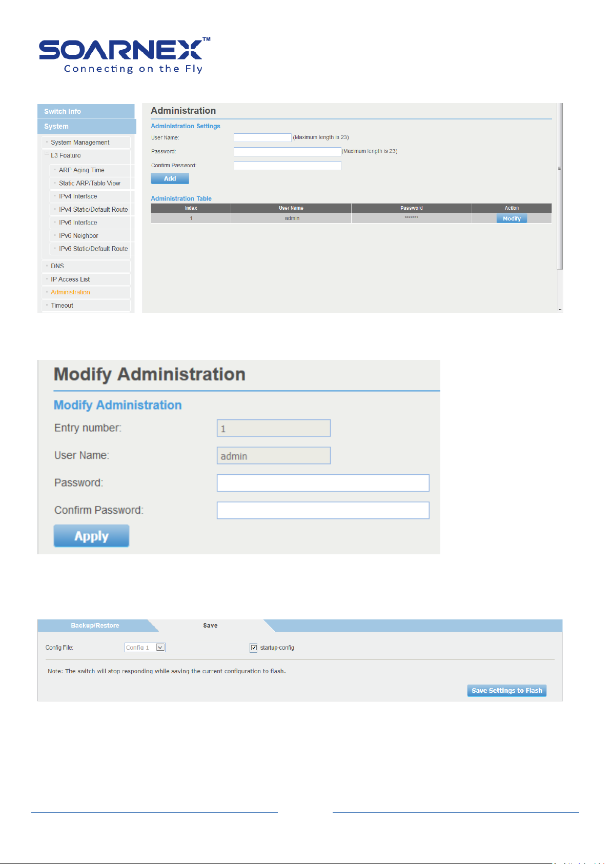
(1)-1 On the left hand side of the web screen, Select System -> Administration
Figure 4-1-3 System -> Administration page
(1)-2 Click Modify button to change default password for the “admin” account.
User Manual
Figure 4-1-4 modify account’s password.
(1)-3 On the left hand side of the web screen, select Tools -> Configuration then choice Save page, Click
“Save Settings to Flash” button to save the configuration from the RAM to FLASH.
Figure 4-1-5 save Settings to Flash
EG210 Series L2+ Smart Managed Switch
9
User Manual
(2) Configure the management Switch via management utility “S-View”
The administrator can visually manage and maintain the Switch through management utility “S-View”.
S-View allows user to discover multiple management Switches in the same L2 network via user's local PC.
With this management utility, user do not need to change the IP Address of the PC and management
Switch with the same L2 network segment, management Switch have displayed on the screen for instant
access. It allows user to configure basic configurations such as a password changed or firmware upgraded.
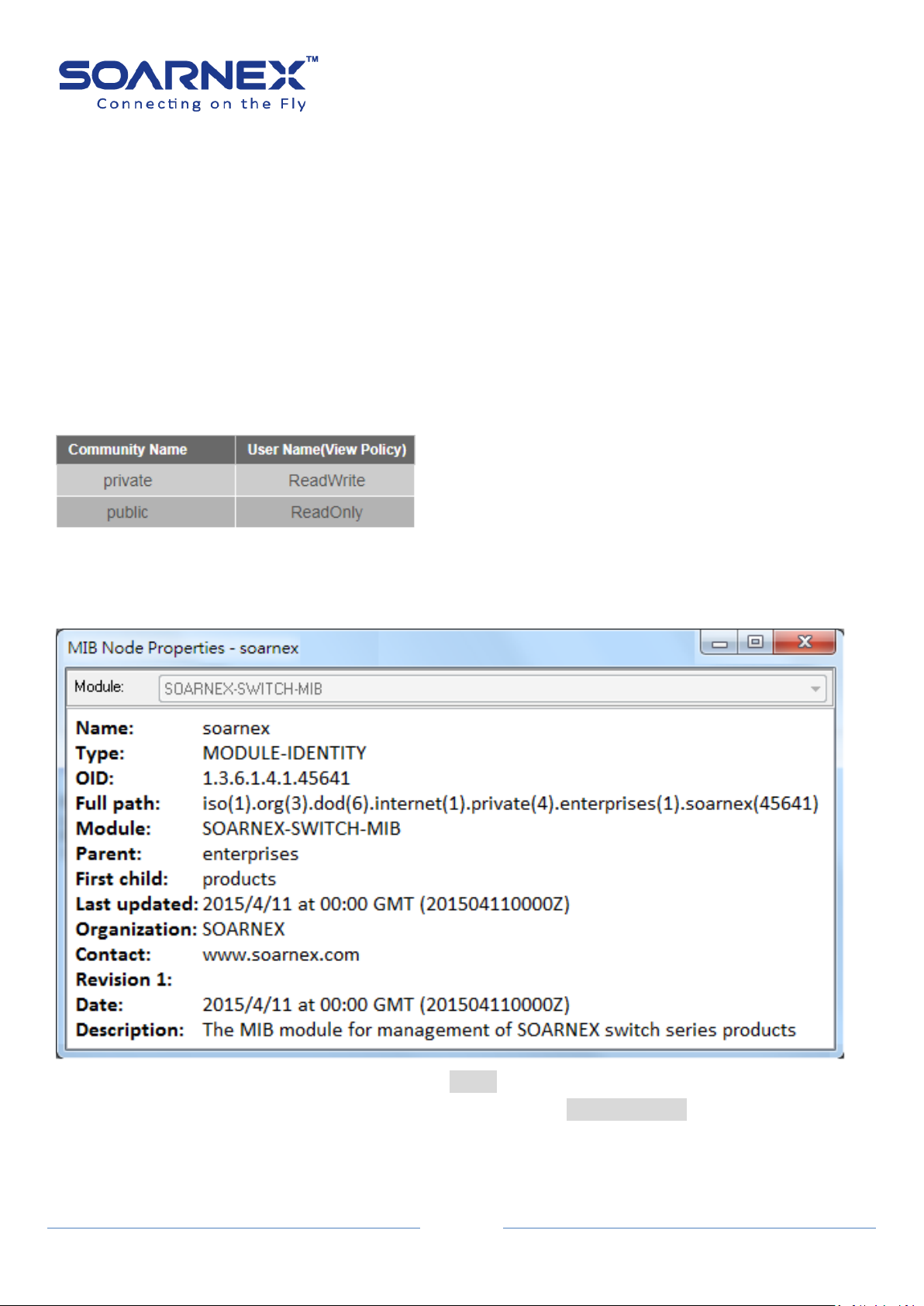
(3) Configure the management Switch via SNMP
By default, Switch SNMP Agent is enabled (SNMPv1).If the SNMP Community Name is “Private” which is for
READ and WRITES policy. And if the SNMP Community Name is “public” which supports READ ONLY policy.
The administrator can use SNMP community utility to READ and WRITES the parameters.
Figure 4-1-6 Default SNMP community Name
Note: SOARNEX MIB id is 45641, the Administrator could import SOARNEX private MIB file to the SNMP
management utility, and then to READ and WRITES the parameters on the Switch.
Figure 4-1-7 SOARNEX private MIB OID: 1.3.6.1.4.1.45641
Full path: iso(1).org(3).dod(6).internet(1).private(4).enterprises(1).soarnex(45641)

EG210 Series L2+ Smart Managed Switch
10
User Manual
For example, the administrator use SNMP management utility to READ and WRITES the Switch parameters.
Figure 4-1-8 example of the SNMP management utility
EG210 Series L2+ Smart Managed Switch
11
User Manual
Chapter 5. Main Features
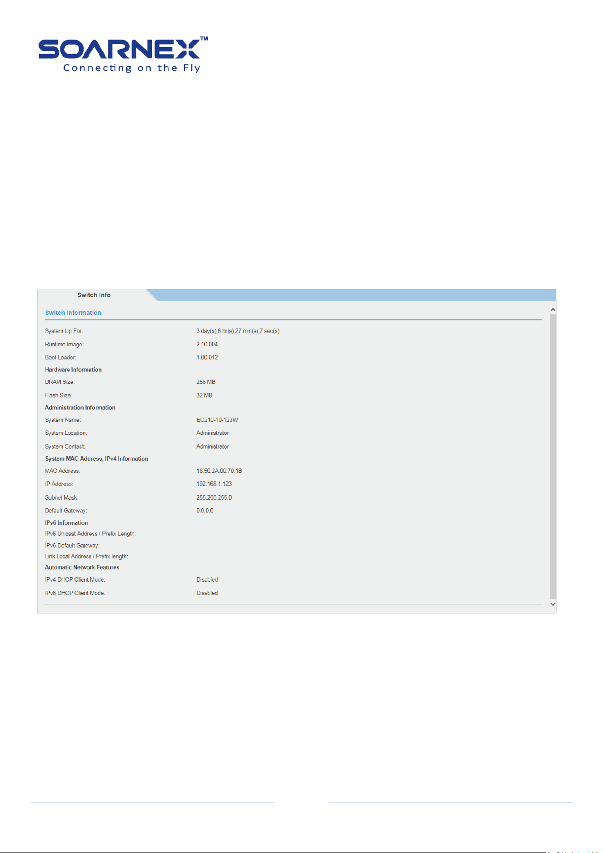
1. Switch Info
1-1. Switch Info
The general System, Hardware, Administration, System MAC Address, IPv4, IPv6, and Automatic Network
Features information of the Switch shown as the following could be easily found on the Switch Info page.
Figure 5-1-1 Switch Information page
EG210 Series L2+ Smart Managed Switch
12
Switch Information
System Up For
Display the duration that the Switch has been running continuously
without a restart or power cycle (hard of software reboot) or reset.
Runtime Image
Display current firmware version.
Boot Loader
Display current boot loader version.
Hardware Information
DRAM Size
Display the Switch RAM memory size.
Flash Size
Displays the Switch Flash memory size.
Administration Information
System Name
Display the Identifying system name of the Switch.
The System Name information can be modified on the SNMP page.
System Location
Display the Identifying system location of the Switch.
The System Location Information can be modified on the SNMP page.
System Contact
Display the Identifying System Contact Information of the Switch.
The System Contact Information can be modified on the SNMP page.
System MAC Address, IPv4 Information
MAC Address
Display system MAC Address.
IP Address
Display the IPv4 Address assigned to the Switch.
Subnet Mask
Display the IPv4 subnet mask assigned to the Switch.
Default Gateway
Display the gateway Address assigned to the Switch.
IPv6 Information
IPv6 Unicast Address / Prefix
Length
Display the IPv6 Unicast Address and Prefix Length assigned to the
Switch.
IPv6 Default Gateway
Display the default gateway Address assigned to the Switch.
Link Local Address / Prefix Length
Display the IPv6 Link Local Address and Prefix Length assigned to the
Switch.
Automatic Network Features
IPv4 DHCP Client Mode
Display IPv4 DHCP Client Mode enabled or disabled status.
IPv6 DHCP Client Mode
Display IPv6 DHCP Client Mode enabled or disabled status
User Manual

EG210 Series L2+ Smart Managed Switch
13
Management
System Description
Display the model name of this Switch.
System Object ID
The System Object ID (SNMP MIB object ID) uniquely identifies the
system. The private MIB OID is "1.3.6.1.4.1.45641".
System Name
Type specified Name for the Switch; the name is optional and
maximum up to 15 characters.
System Location
Type specified Location for the Switch; the name is optional and
maximum up to 30 characters.
System Contact
Type specified Contact for the Switch; the name is optional and
maximum up to 30 characters.
User Manual
2. System
2-1. System Management
The user can assign a System Name, System Location, and System Contact information for the Switch.
This information helps an administrator to identify each specified Switch among other Switches in the
network.
Figure 5-2-1-1 System Management – System setting page

14
2-2. L3 Feature
IPv4 Interface
Interface VLAN
Enter the VLAN ID (1-4094) to create logic L3 VLAN interface.
Add/Find button
User can manually add VLAN ID by clicking Add button. Before add
VLAN ID to create logic L3 VLAN interface, user needs specifies the
VLAN ID in “VLAN Tagged VLAN” page.
User can find specifies logic L3 VLAN interface setting by clicking Find
button.
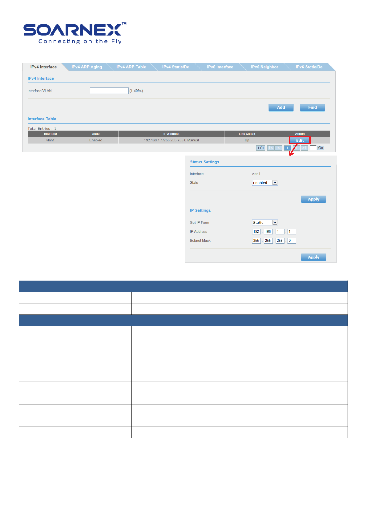
2-2-1. IPv4 Interface
The IPv4 interface page allows user to configure the IPv4 address settings of logic L3 VLAN
interface. The default System IP address setting is Static with IP address and subnet mask as
192.168.1.1 and 255.255.255.0
EG210 Series L2+ Smart Managed Switch
User Manual
Figure 5-2-2-1-1 IPv4 Interface
EG210 Series L2+ Smart Managed Switch
15
IPv4 Interface Configuration (Status Settings)
Interface
Display the logic L3 VLAN interface name.
State
Click pull-down list to Enable or Disable the logic L3 VLAN interface.
IPv4 Interface Configuration (IP Settings)
Get IP Form
Select Static mode in “Get IP Form” pull-down list, the user can
manually configure the Logic L3 VLAN interface IPv4 Address.
Select DHCP mode in “Get IP Form” pull-down list, the logic L3 VLAN
interface obtain the IPv4 Address from a DHCP server in the network
by auto.
IP Address
Enter the IP Address of logic L3 VLAN interface.
(Default: 192.168.1.1)
Subnet Mask
Enter the Subnet Mask logic L3 VLAN interface.
(Default: 255.255.255.0)
Apply button
Click "Apply" button to accept the changes.
User Manual
In the interface table, user can modify the logic L3 VLAN interface IP Address by clicking Edit button.
Figure 5-2-2-1-2 IPv4 Interface configuration

EG210 Series L2+ Smart Managed Switch
16
Interface Table
Total Entries
Indicate to the number of total logic L3 VLAN interface entries.
Interface
Display the logic L3 VLAN interface name.
State
The state of logic L3 VLAN interface (Enable or Disable)
IP Address
Display the IP Address and types (get IP from) of the logic L3 VLAN
interface.
Link Status
Display the link status of the logic L3 VLAN interface.
The Up status means there is a port is active in the logic L3 VLAN
interface.
The Down status means there is NO port is active in the logic L3 VLAN
interface.
Action
The logic L3 VLAN IPv4 interface allows user to Edit and delete
manually by clicking Edit or Delete button.
Figure 5-2-2-1-3 Interface Table
User Manual
2-2-2. IPv4 ARP Aging Time
Specifies the ARP aging time of the logical L3 VLAN interface, you also can configure the
logical L3 VLAN interfaces ARP aging time individually.
Figure 5-2-2-2 IPv4 ARP Aging Time

EG210 Series L2+ Smart Managed Switch
17
ARP Aging Time
Interface Name
Display this VLAN name information, that is identifies the VLAN of the
user wishes to modify the ARP Aging time settings.
Timeout
Specifies the ARP aging timeout of the logical L3 VLAN interface.
The range is 0 through 65535 minutes. A value of 0 indicates that the
entry should never be aged out.
The default ARP aging timeout values is 20 minutes.
Action
Click Edit button in Action field, which will allow user change
“Timeout” value; click Apply button to accept the changes.
ARP Aging Time
IP Address
To specifies the IPv4 Address of the ARP entry.
Hardware Address
To specifies the MAC Address of the ARP entry.
Apply
To click Apply button to create the ARP entry.
Static ARP Table
Interface Name
Display this VLAN name information, that is identifies the VLAN of the
user wishes to modify the ARP Aging time settings.
IP Address
Display the IP Address of the ARP entry.
Hardware Address
Display the MAC Address of the ARP entry.
User Manual
2-2-3. IPv4 ARP Table
The ARP table allows network managers to view, modify and delete the ARP entire for a
devices. The entire used to translate IP Address to MAC Address and the static ARP entry is a
permanent entry in the ARP table.
Before create static ARP table entire, you have to know the logic L3 interface IP Subnet
address. The static ARP entry only allows network manager to create when the entry's IP
subnet the same as L3 interface's subnet.
Figure 5-2-2-3 IPv4 ARP Table
EG210 Series L2+ Smart Managed Switch
18
Aging Time
Display the ARP aging timeout value of the ARP entry.
Type
Display the ARP entry types (Dynamic/Static).
The ARP table can contain dynamic (learned) entries and static
(create by network manager) entries.
Action
Network manager can click Delete button to delete the ARP entry
that listed on ARP table.
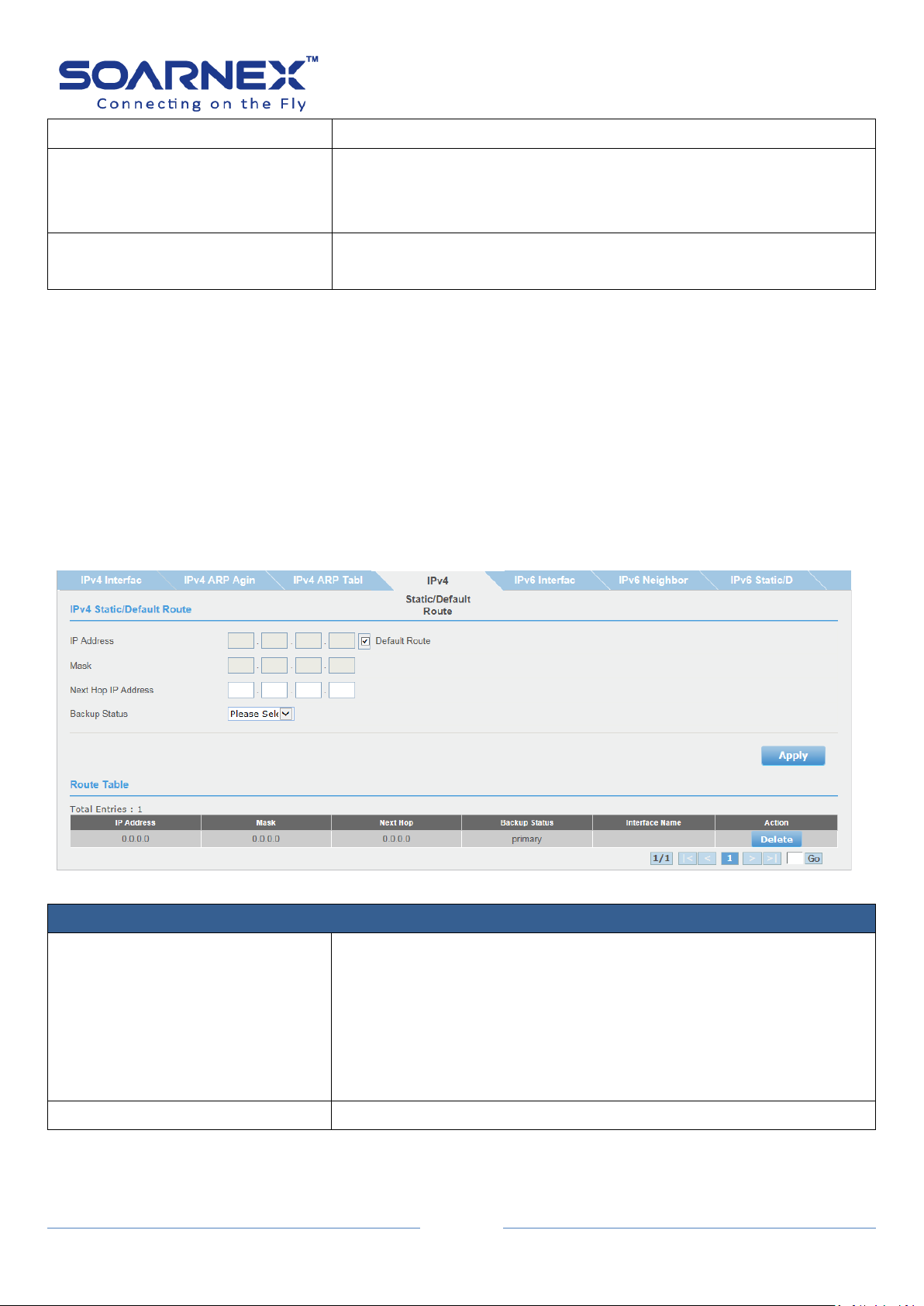
IPv4 Static/Default Route
IP Address
When the Default Route check-box is changed to inactive, the
network administrator can specifies the mask of the IPv4 destination
address of the route. By default, the IPv4 Default Route check-box is
active with 0.0.0.0 for the default gateway address.
Note, the default gateway address 0.0.0.0 means there is no default
gateway address.
Mask
Enter the Subnet Mask of the IPv4 address.
User Manual
2-2-4. IPv4 Static/Default Route
The EG210 series managed switch supports L3 static route for IPv4/IPv6. The network
administrator can create static routes for the switch, once a static route has been create, the
switch will send ARP requests packets to the gateway address for make sure the static route
entry is alive. The network administrator can used the static route for specifies destination
IPv4 address/subnet mask with gateway address, the matched the route entry packets are
forward to this gateway address. The network administrator also can use the default route
for all of the packets that the destinations address out of the local network.
Figure 5-2-2-4 IPv4 Static/Default Route
EG210 Series L2+ Smart Managed Switch
19
Next Hop IP Address
The Next Hop IP Address as the gateway address for the "IPv4
destination address/Subnet mask" or the "packets out of the local
network (default route)".
The Next Hop IP Address is used when the packets are failed to
forward and the destination address can't match any entry in the
routing table, the switch uses the default route to forward the packet.
If the network administrator specifies the destination IPv4
address/mask with gateway address, the matched packets are
forward to this Next Hop IP Address.
Backup Status
Each IPv4 destination address of the route can have one Primary and
one Backup gateway address. If the primary route failed (e.g. lost the
connection), the switch will forward those packets to backup gateway
address.
Apply button
Click "Apply" button to accept the changes.
Route Table
Total Entries
Indicate to the number of total route table entries.
IP Address
Display theIPv4 destination address of the route entry.
Mask
Display the IPv4 subnet mask of the route entry.
Next Hop
Display the Next Hop (gateway address) of the route entry.
Backup Status
Display the IPv4 destination address of the route is Primary and
Backup gateway address.
Interface Name
Display the logic L3 VLAN interface name.
Action
The static route entry allows user to delete manually by clicking
Delete button.
User Manual
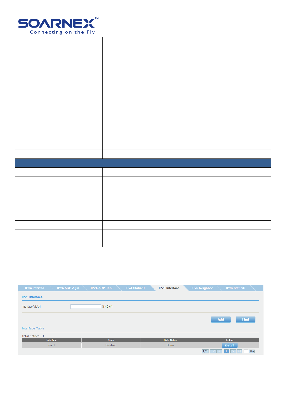
2-2-5. IPv6 Interface
The IPv6 Interface page allows user to configure the IPv6 address manually.
Figure 5-2-2-5-1 IPv6 Interface

EG210 Series L2+ Smart Managed Switch
20
IPv6 Interface
Interface VLAN
Enter the VLAN ID (1-4094) to create logic L3 VLAN interface.
Add/Find button
User can manually add VLAN ID by clicking Add button. Before add
VLAN ID to create logic L3 VLAN interface, user needs specifies the
VLAN ID in “VLAN Tagged VLAN” page.
User can find specifies logic L3 VLAN interface setting by clicking Find
button.
Interface Table
Total Entries
Indicate to the number of total logic L3 VLAN interface entries.
Interface
Display the logic L3 VLAN interface name.
State
The state of logic L3 VLAN interface (Enable or Disable)
Action
To modify the logic L3 VLAN interface IPv6 Address by click Detail
button.
User Manual
In the interface table, user can modify the logic L3 VLAN interface IP Address by clicking
Detail button.

EG210 Series L2+ Smart Managed Switch
21
IPv6 Interface Configuration (Status Settings)
Interface
Display the logic L3 VLAN interface name.
State
User can manually enable/disable the logic L3 VLAN interface.
Apply button
Click "Apply" button to accept the changes
IPv6 Interface Configuration (IP Settings)
DHCPv6 Client status
Specify the DHCPv6 client to be Enabled or Disabled.
The Rapid Commit option is used to signal the use of the two
message exchange for address assignment.
User Manual
Figure 5-2-2-5-2 IPv6 Interface configuration
EG210 Series L2+ Smart Managed Switch
22
IPv6 Address
By default, when user enabled IPv6 interface, a Link-Local Address is
automatically configured by Switch’s 48-Bit MAC Address to IPv6
modified EUI-64 Identifier.
User also can manually configure the “Link Local Address/Prefix
length” or “Global Unicast IPv6 Address/Prefix length” for the L3
VLAN IPv6 interface.
Apply button
Click "Apply" button to accept the changes.
NS Retransmit Time
NS Interval
A constant to define a nonzero number of times between periodic NS
packets. The field is from 1 to3600 seconds. The default setting is 1
second.
When user sets up IPv6 Default Gateway, a NS packet should be sent
out if the specified Gateway is no longer exist. The retry is 3 times
(i.e. NS should be sent out) by following NS Retransmit Time Interval.
Apply button
Click "Apply" button to accept the changes.
Interface Table
Total Entries
Indicate to the number of total logic L3 VLAN interface entries.
Address Type
To display the IPv6 Address types “Global Unicast IPv6 Address” or
“Link-Local Address”
IPv6 Address
To display IPv6 Address/Prefix length information.
Action
The IPv6 Address entry allows user to delete manually by clicking
Delete button.
User Manual

EG210 Series L2+ Smart Managed Switch
23
IPv6 Neighbor Settings
Neighbor IPv6 Address
Specify the neighbor IPv6 address.
Link Layer MAC Address
Specify the link layer MAC address.
Status
Display the Switch IPv6 Neighbor IPv6 Address and Link Layer MAC
Address learned by Static added or Dynamic learned.
Note: If user cannot find the IPv6 Neighbor in the list, he needs to
access the Switch IPv6 Link-Local Address or IPv6 Unicast Address
from the neighbors.
There are three states as below:
All:
For Find button only, the ALL state for display all learned IPv6
Neighbor information.
Static:
Display manual added (Static Added Neighbor IPv6 Address/Link
Layer MAC Address in the switch) IPv6 Neighbor IPv6 Address
information.
Dynamic:
Display dynamic learned IPv6 Neighbor IPv6 Address information.
User Manual
2-2-6. IPv6 Neighbor
User can manually add on IPv6 Neighbor Address and Link Layer MAC Address by clicking
Add button on IPv6 Neighbor page, and user also can find all static added and dynamic
learned IPv6 Neighbor information on this page.
Figure 5-2-2-6 IPv6 Neighbor

EG210 Series L2+ Smart Managed Switch
24
Action
There are two buttons for the Action:
Find:
User can specify the neighbor IPv6 address and the link layer MAC
address and then click the Find button to display you specifies list.
Delete:
User can delete All entries when the Neighbor IPv6 Address and the
link layer MAC Address field set to * then click Delete button.
He also can delete each entry by click the Delete button one by one.
IPv6 Static/Default Route
IPv6 Address/Prefix length
When the Default Route check-box is changed to inactive, the
network administrator can specifies the IPv6 destination
address/prefix length of the route.
Interface VLAN
Enter the VLAN ID (1-4094) to create logic L3 VLAN interface.
User Manual
2-2-7. IPv6 Static/Default Route
The EG210 series managed switch supports L3 static route for IPv4/IPv6. The network
administrator can create static routes for the switch, once a static route has been create, the
switch will send NS packets to the next hop address for make sure the next hop address is
valid. The network administrator can used the static route for specifies destination IPv6
address/prefix length with next hop address, the matched the route entry packets are
forward to this next hop address. The network administrator also can use the default route
for all of the packets that the destinations address out of the local network.
Figure 5-2-2-7 IPv6 Static/Default Route

EG210 Series L2+ Smart Managed Switch
25
Next Hop IPv6 Address
The Next Hop IPv6 Address used for forward IPv6 packets to the
specified network. The Next Hop node need
Please do not use
Do not use IPv6 Link-Local Address, Unique Local Address (ULA), or
the IPv6 Address of the Switch as the IPv6 Next Hop Address.
Backup Status
Each IPv6 destination Address of the route can have one Primary and
one Backup Next Hop IPv6 Address. If the primary route failed (e.g.
lost the connection), the switch will forward those packets to backup
Next Hop IPv6 Address.
Apply button
Click "Apply" button to accept the changes.
Route Table
Total Entries
Indicate to the number of total route table entries.
IPv6 Address Prefix Length
Display IPv6 Address/Prefix Length of the route entry.
Next Hop
Display the Next Hop IPv6 Address of the route entry.
Interface Name
Display the logic L3 VLAN interface name.
Protocol
C – Connected;
S - Static,
- Selected Route,
* - Valid Route
Action
The static route entry allows user to delete manually by clicking
Delete button.
User Manual
2-3. DNS
If the Switch has required name resolution services (e.g. SNTP service), user has to setup the
DNS server settings. The Switch allows user to configure DNS IPv4/IPv6 server for DNS query
when IPv4 DNS server is configured, and domain query setup for IPv4 DNS server at first.
The DNS Server correlates IP addresses to host names when queried.
Figure 5-2-3 DNS

26
DNS Server Settings
DNS IPv4 Server
Specify the IPv4 DNS server Address.
DNS IPv6 Server
Specify the IPv6 DNS server Address.
Apply button
Click Apply button to accept the changes.
2-4. IP Access List
The IP Access List allows user to define or restrict the access to a list of specified IP
addresses on the switch management page.
EG210 Series L2+ Smart Managed Switch
User Manual
Figure 5-2-4 IP Access List
EG210 Series L2+ Smart Managed Switch
27
IP Access List
IP Restriction Status
Enable or Disable IP Restriction.
Before enable the IP Restriction status, user must create at least one
IP Address first (if the IP Access List table is empty, the GUI will
pup-up warning message “Current Table is empty, cannot be
enabled”)
The Default status is Disabled.
Apply button
Click "Apply" button to accept the changes.
IP Address Settings
IP Address
IPv4:
User can add IP Access Control Entry to allow adding IPv4 Address
access on the switch management page.
IPv6:
User can add IP Access Control entry to allow adding IPv6 Address
access on the switch management page.
The IPv6 Address can be Global Unicast IPv6 Address or Link-Local
IPv6 Address.
Add button
Click "Add" button to create IPv4/IPv6 address.
IP Access List table
Index
Display added IP Access entry index number.
Accessible IP
Display the IP Address information which user has added.
Action
User can delete the entry that he has added on IP Access list table.
User Manual

EG210 Series L2+ Smart Managed Switch
28
Administration Settings
User Name
Enter a user name for new account.
The user name consists of up to 20 alphanumeric characters.
Password
Enter a password for new account.
The password consists of up to 20 alphanumeric characters.
Confirm Password
Enter a password again for verification.
Add
Click Add button to create new account,
Administration Table
Index
Display user account index number.
The maximum entries of user accounts are eight.
User Name
Display added user account name.
Password
Display added user account password.
Action
Modify:
User can click Modify button to change created user account’s
password.
The index 1 “admin” user on the administration table is the default
administrator for which user can not remove it; but he could modify
the default user name and password here.
Delete:
User can click Delete button to delete created user account.
2-5. Administration
The default user name and password for the management Switch are “admin”. User can
change the admin password or create additional administrative user accounts for accessing
to the management page.
User Manual
Figure 5-2-5 Administration

29
2-6. Timeout
Timeout Settings
Web Idle Timeout
Enter the idle period in minutes (3-60 minutes), and after the Switch
will automatically log out a user from the switch management page.
The default value is 10 minutes.
Apply button
Click "Apply" button to accept the changes.
The management Switch supports web service by using standard web HTTP protocol; user
can modify web service idle timeout value.
Figure 5-2-6 Timeout
EG210 Series L2+ Smart Managed Switch
User Manual

30
2-7. System Time
The Switch System Time can be manually setup or obtained by SNTP server; the Switch also
allows setting up Daylight Saving Time.
Clock mode: Local
EG210 Series L2+ Smart Managed Switch
User Manual
Figure 5-2-7-1 System Time (Local)

31
Clock mode: SNTP
Current Time Settings
Clock Mode
Display Local Switch Date/Time Settings or obtain this information
from SNTP server.
Current Time
Display current system Date/Time information.
Time Zone
Display current system time zone when the clock mode is SNTP.
EG210 Series L2+ Smart Managed Switch
User Manual
Figure 5-2-7-2 System Time (SNTP)
EG210 Series L2+ Smart Managed Switch
32
Date/Time Settings
Date/Time Settings
Click drop-down list to set the Switch Date/Time Settings mode:
Local Time:
Local Time is Switch’s default Date/Time Settings mode.
SNTP:
User can select SNTP to configure his Switch to have automatically
obtained date/time information from a NTP server.
Local Time Settings
Date Settings
Specify the Switch date settings (YYYY/MM/DD).
Time Settings
Specify the Switch time settings (HH:MM:SS)
Simple Network Time Protocol (SNTP) Settings
SNTP Primary Server
The Switch allows set SNTP Primary Server format as IPv4 Address,
IPv6 Address or Domain Name.
Note:
The primary server should not be empty when date/time settings
mode is SNTP.
SNTP Secondary Server
The Switch allows set SNTP Secondary Server format as IPv4
Address, IPv6 Address or Domain Name.
Note:
The Secondary server allows setup to be empty when date/time
settings mode is SNTP.
SNTP Poll Interval
The SNTP Poll Interval will update the date and time settings with the
NTP server.
Its range is from 1 to 60 minutes. Default value is 1 minute.
Time Zone
The Time Zone is used to configure time zones and Daylight Savings
time settings for SNTP, click the drop-down list to select user’s local
time zone.
Additional Time Parameters
Daylight Saving Time Status
If user’s location is on the daylight saving time zone, the Switch allows
user to enable this function.
From
The “FROM” for the daylight saving time started.
To
The “TO” for the daylight saving time finished.
DST Offset
To set the clocks forward or back.
Apply button
Click "Apply" button to accept the changes.
User Manual
The Local Time Settings parameters only can be configured when the Date/Time Settings mode is Local
Time.
The Simple Network Time Protocol (SNTP) Settings only can be configured when the Date/Time Settings
mode is SNTP.
33
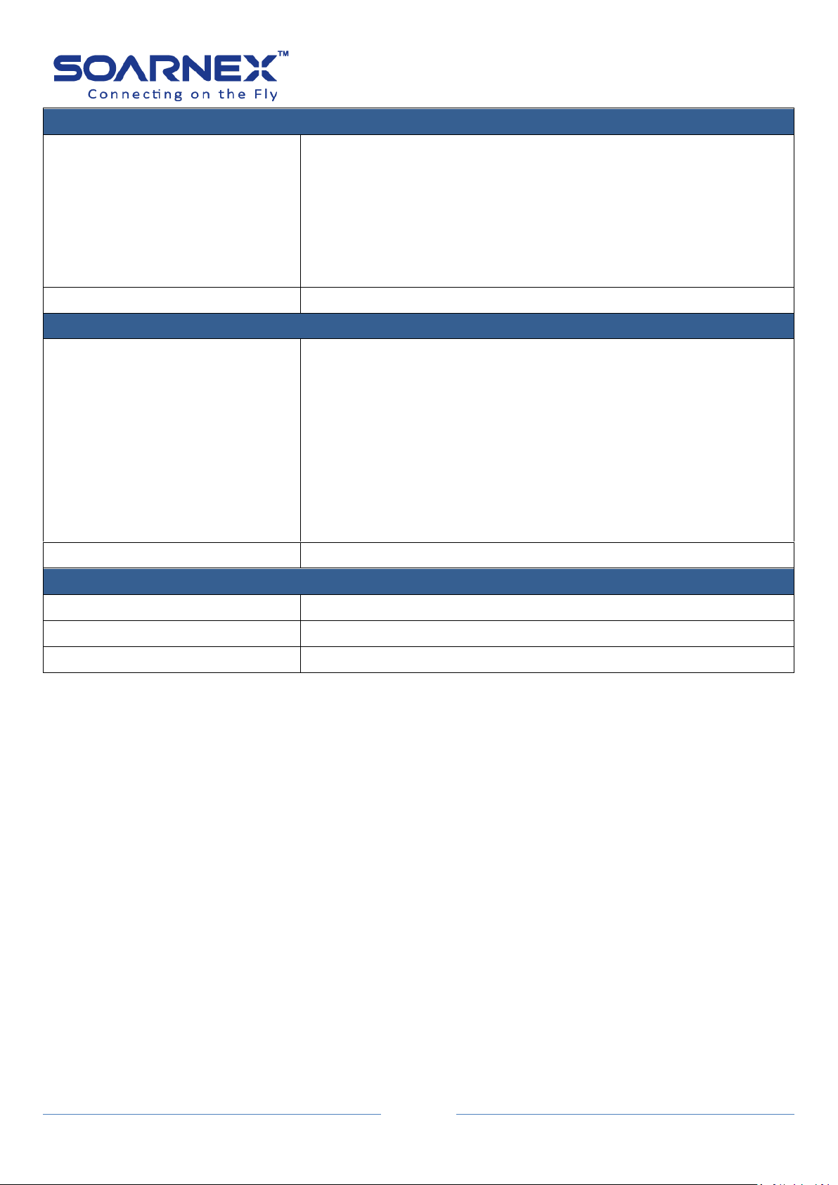
2-8. SSL
SSL Settings
SSL Status
Click drop-down list to Enable or Disable HTTPS/SSL management
access. The Default is disabled.
Apply button
Click "Apply" button to accept the changes.
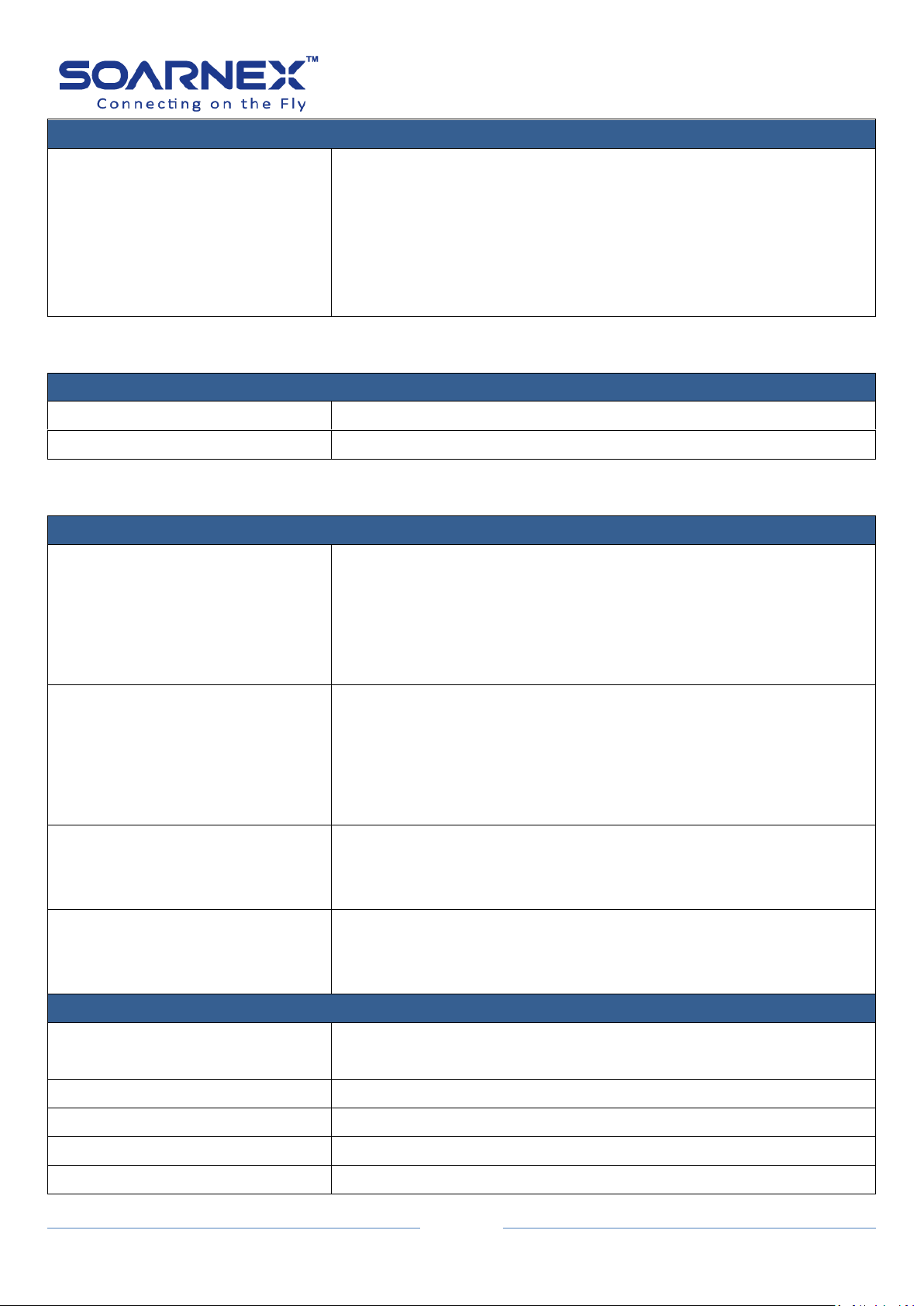
SSH Settings
SSH
Click drop-down list to Enable or Disable SSH service. The Default is
Disabled.
Port (1-65535)
The TCP port number used for SSH service of the Switch. The
"well-known" TCP port for the Telnet service is 22.
User also can change the port number for SSH service. The range is
from 1 to 65535.
Apply button
Click "Apply" button to accept the changes.
By default, the management Switch enables a web service by using standard web HTTP
protocol for the management page. The standard web HTTP protocol transmits files with
clear text over the network. User can enable HTTPs/SSL to allow accessing to the Switch
management page by using encrypted communication.
Figure 5-2-8 SSL
EG210 Series L2+ Smart Managed Switch
User Manual
2-9. SSH
The management Switch supports SSH (Secure Shell) service for administrator by using the
Command Line Interface (CLI) remotely and secure. By default, the SSH (Secure Shell) service
is disabled.
Figure 5-2-9 SSH
34
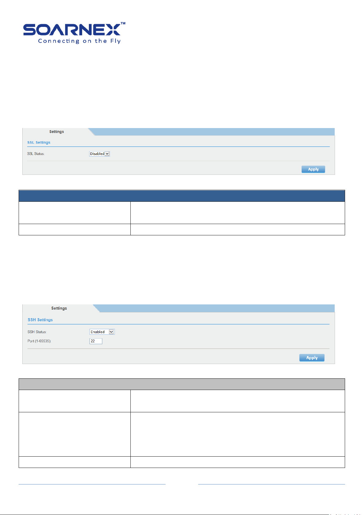
2-10. Telnet
Telnet Settings
Telnet
Click drop-down list to Enable or Disable Telnet service. The Default is
Enabled.
Port (1-65535)
The TCP port number used for Telnet service of the Switch. The
"well-known" TCP port for the Telnet service is 23.
User also can change the port number for Telnet service. The range is
from 1 to 65535.
Apply button
Click "Apply" button to accept the changes.
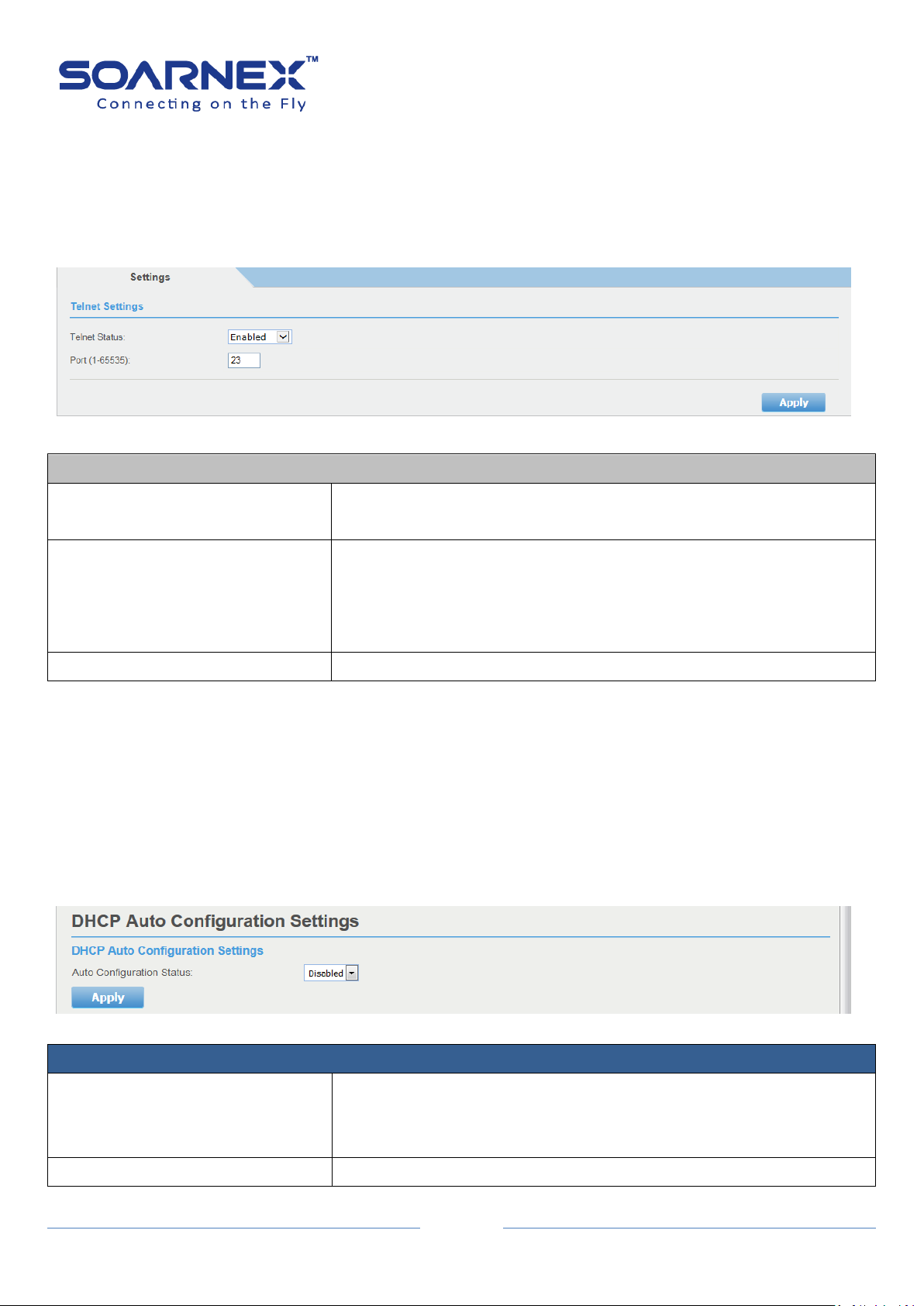
DHCP Auto Configuration Settings
Auto Configuration Status
Click pull-down list to Enable or Disable Auto Configuration state.
Enable: The Switch gets IP Address from DHCP server and gets the
configuration file from TFTP server. The Default is Disabled.
Apply button
Click "Apply" button to accept the changes.
The management Switch supports Telnet service for administrator by using the Command
Line Interface (CLI) remotely. By default, the Telnet service is enabled.
Figure 5-2-10 Telnet
EG210 Series L2+ Smart Managed Switch
User Manual
2-11. DHCP Auto Configuration
When enabled Switch wants to become a DHCP client and gets the configuration file from a
TFTP server automatically, to accomplish this, DHCP server must deliver the TFTP server IP
address and configuration file name information in the DHCP reply packet. The TFTP server
must start and store the necessary configuration file in its base directory when the request is
received from the Switch.
Figure 5-2-11 DHCP Auto Configuration

35
2-12. System Log
The system log is designed to monitor the Switch operation by recording and managing the
events, and to report errors and informational messages as well.
These events may provide system important activity information which can help identifying
and resolving system problems.
EG210 Series L2+ Smart Managed Switch
User Manual
Figure 5-2-12 System Log

EG210 Series L2+ Smart Managed Switch
36
System Log
Time Stamp
Click pull-down list to Enable or Disable the time stamp on log entry.
Default: Enabled.
Message Buffered Size
Enter the message buffer size.
Default: 50 entries, Its range is from 1 to 512.
Syslog Status
Click pull-down list to Enable or Disable to store the logs on remote
log server. Default: Disabled.
Syslog Server IP
Enter the IPv4 or Ipv6 address of the syslog server to send logging
information.
Facility
Click the drop-down list to define which facility to be used to store
the logging. (Options: local0 – local7)
Note:
User can define the facility to store logging on his external syslog
server.
This helps to ensure a user who has a separate logging section for
different devices.
Logging Level
Click the drop-down list to select what level of event messages that
Logging Level determines a set of event messages that will be sent..
Alert:
Action must be taken immediately.
Critical:
Critical conditions are displayed.
Warning:
Warning conditions are displayed.
Informational:
Informational messages are displayed.
Clear/Flash button
Clear button:
User can delete all log messages by click Clear button
Flash button:
User can click Flash button to renew all log messages.
User Manual
37
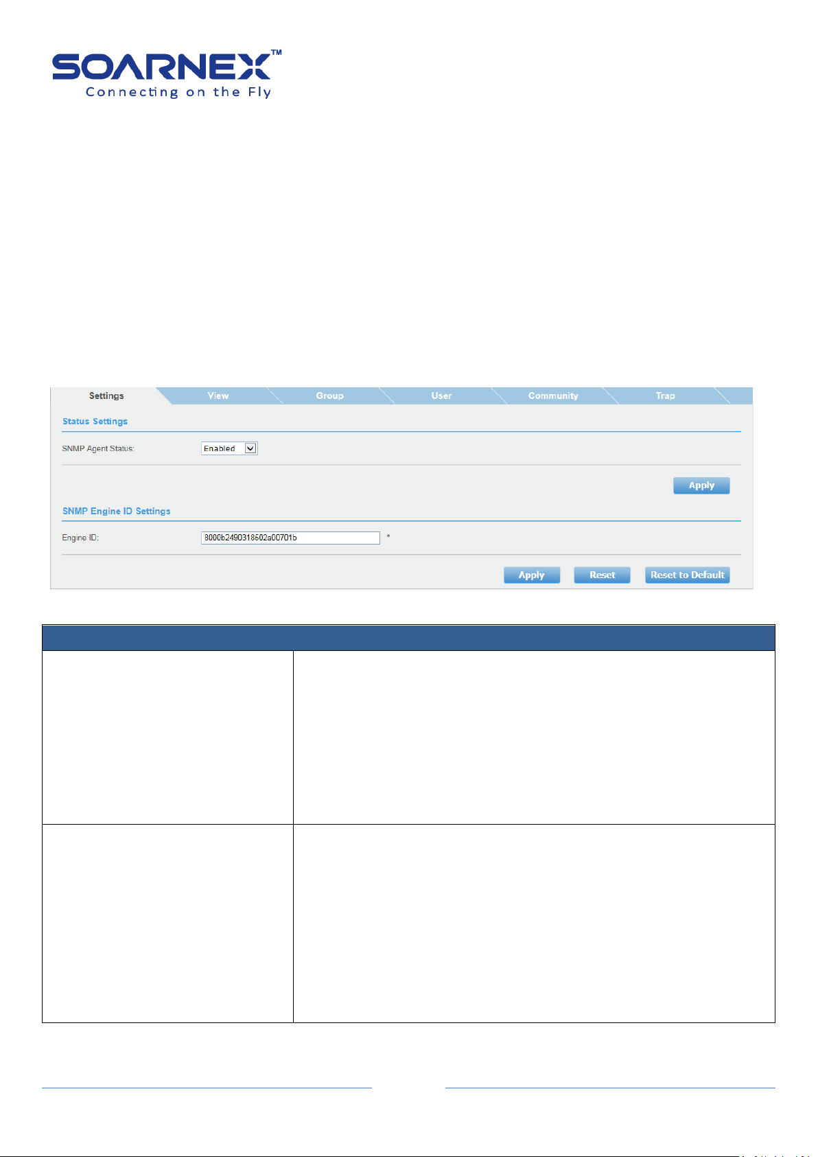
2-13. SNMP
SNMP Settings
SNMP Agent Status
Click the drop-down list to Enable or Disable SNMP agent.
SNMP Agent is enabled and active as default. And user can manage
the Switch by SNMP network management software.
Enable: The SNMP agent is active.
Disabled: The SNMP agent is inactive.
Note: If user has changed SNMP Agent parameter to Enable or
Disable, he needs to click Apply button to accept the changes.
Engine ID
The Engine ID is a hexadecimal string and is a unique identifier to
identify the SNMPv3 engine on the Switch. The Engine ID must be
defined before SNMP is enabled.
The Engine ID value is 10 - 64 Hexadecimal digits. By default, the
Switch Engine ID default value is following RFC3411 standard, the
Engine ID is consisted of “Enterprise ID and MAC Address”
Note: If user has changed Engine ID value, he needs to click Apply
button to accept the changes.
Simple Network Management Protocol (SNMP) is an OSI Layer 7 (Application Layer) protocol
which user can manage and monitor the Switch via SNMP with (MIB) object on the Switch. A
Group Name and IP address of the Switch and one Community Name are required to
manage the Switch via SNMP at least.
Note: SNMP agent has only listened to the requests received from port 161.
2-13-1. Settings
EG210 Series L2+ Smart Managed Switch
User Manual
Figure 5-2-13-1 SNMP Settings

38
2-13-2. View
SNMP View Settings
View Name
The View Name can contain from 1 to 32 alphanumeric characters.
This value must be pre-created on the SNMP User/Group page.
Subtree OID
Enter an OID string for the Subtree to include or exclude from created
SNMP view.
The OID string format x.x.x.x.x and length is 1-16 (not included “.”).
For example, the system Subtree is specified by the OID
string .1.3.6.1.2.1.11.
OID Mask
The mask of the Subtree OID. 1 means this object number is
concerned, 0 means no concerned.
The OID Mask format consisted by “0” or “1” and the length is 1-16
(not included “.”).
View Type
Click the pull-down list to choose Included or Excluded that a SNMP
manager can access.
Included: Allows the specified MIB object to be included in the view.
Excluded: Blocks the view of the specified MIB object.
The SNMP View OID 1 is created by default in the system which contains all
management object supported by the Switch. User can create SNMP view
table to control the SNMP OID ranges to be accessed or denied based on the
entries table. User also can create and delete entries in the View table.
EG210 Series L2+ Smart Managed Switch
User Manual
Figure 5-2-13-2 SNMP – View Settings
For example, to create a view that excludes the Subtree 1.3.6.1.2.1.11, create an excluded entry with
default View Name “ReadWrite”, the Subtree OID 1.3.6.1.2.1.11 and OID Mask value 1.1.1.1.1.1.1.0, then
the Subtree snmp(11) denied for access.

EG210 Series L2+ Smart Managed Switch
39
SNMP View Table
View Name
Display created and default View Name entries.
The default entry of View Name is “ReadWrite”.
Subtree OID
Display each entry Subtree OID.
The default entry of View Name is “ReadWrite” and the Subtree OID
is “1”.
OID Mask
Display each entry OID Mask.
The default entry of View Name is “ReadWrite” and the OID Mask “1”.
View Type
Display each entry View Type (included or excluded)
The default entry of View Name IS “ReadWrite” and the View Type is
included.
Action
User can delete created entry by click “Delete” button.
Note: The default entry “ReadWrite” cannot be deleted it.
User Manual
2-13-3. Group
The SNMP View Names are defined in the SNMP Group Access Table and are
based on the User and Group Names. You must pre-create a Group Name
using the SNMP User/Group page first.
Figure 5-2-13-3 SNMP –Group Access Settings

EG210 Series L2+ Smart Managed Switch
40
SNMP Group Access Settings
Group Name
Specify the SNMP user group, the range is from 1 to 32 characters.
Note: user must pre-create a Group Name using the SNMP
User/Group page first.
Read View Name
Specify a SNMP Read View Name for user who is allowed to view and
read the Switch via SNMP MIBs. The range is from 1 to 32 characters.
Write View Name
Specify a SNMP Write View Name for user who is allowed to create,
alter, and delete the Switch via SNMP MIBs. The range is from 1 to 32
characters.
Notify View Name
Specify a SNMP Notify View Name for user to send notifications to
members in the group. The range is from 1 to 32 characters.
Security Model
Click pull-down list to select the SNMP security model.
v1:
SNMPv1 does not support the security features.
The default setting of SNMP Security Mode is SNMPv1
v2c:
SNMPv2 supports both centralized and distributed network
management strategies, SNMPv2 also compatibility SNMPv1, Get
Bulk support mechanisms, SNMPv2 can provide detailed error
information type.
v3:
SNMPv3 provides secure access to devices through a combination of
authentication and encrypting packets over the network.
Security Level
The Security Level only supports in SNMP Security Mode set to v3.
NoAuthNoPriv:
There are no authentication and encryption packets to be sent
between the Switch and SNMP manager.
AuthNoPriv:
Authorization is required, but there is non-encryption packet
acceptable to be sent between the Switch and SNMP manager.
AuthPriv:
With the security level, users send an MD5 key/password for
authentication and a DES key/password with encryption.
When encryption has been enabled but only the Auth-Protocol has a
password assigned and the Priv-Protocol has been selected as none
on the SNMP User/Group page.
User Manual
EG210 Series L2+ Smart Managed Switch
41
SNMP Group Access Table
Group Name
Display default Group Name “ReadOnly and ReadWrite” and created
Group Name entries.
Read View Name
Display default Group Name entries Read View Name.
Write View Name
Display default Group Name entries Write View Name.
Notify View Name
Display created Notify View Name entries.
Security Model
Display default and created entries Security Mode.
Security Level
Display default and created entries Security Level.
Action
User can click “Delete” button to delete created entry here.
Note, if user needs to modify an entry on the SNMP Group Access
page, first he must delete the entry and after re-enter it.
The ReadOnly and ReadWrite Group Names are default values and
cannot be removed.
User Manual
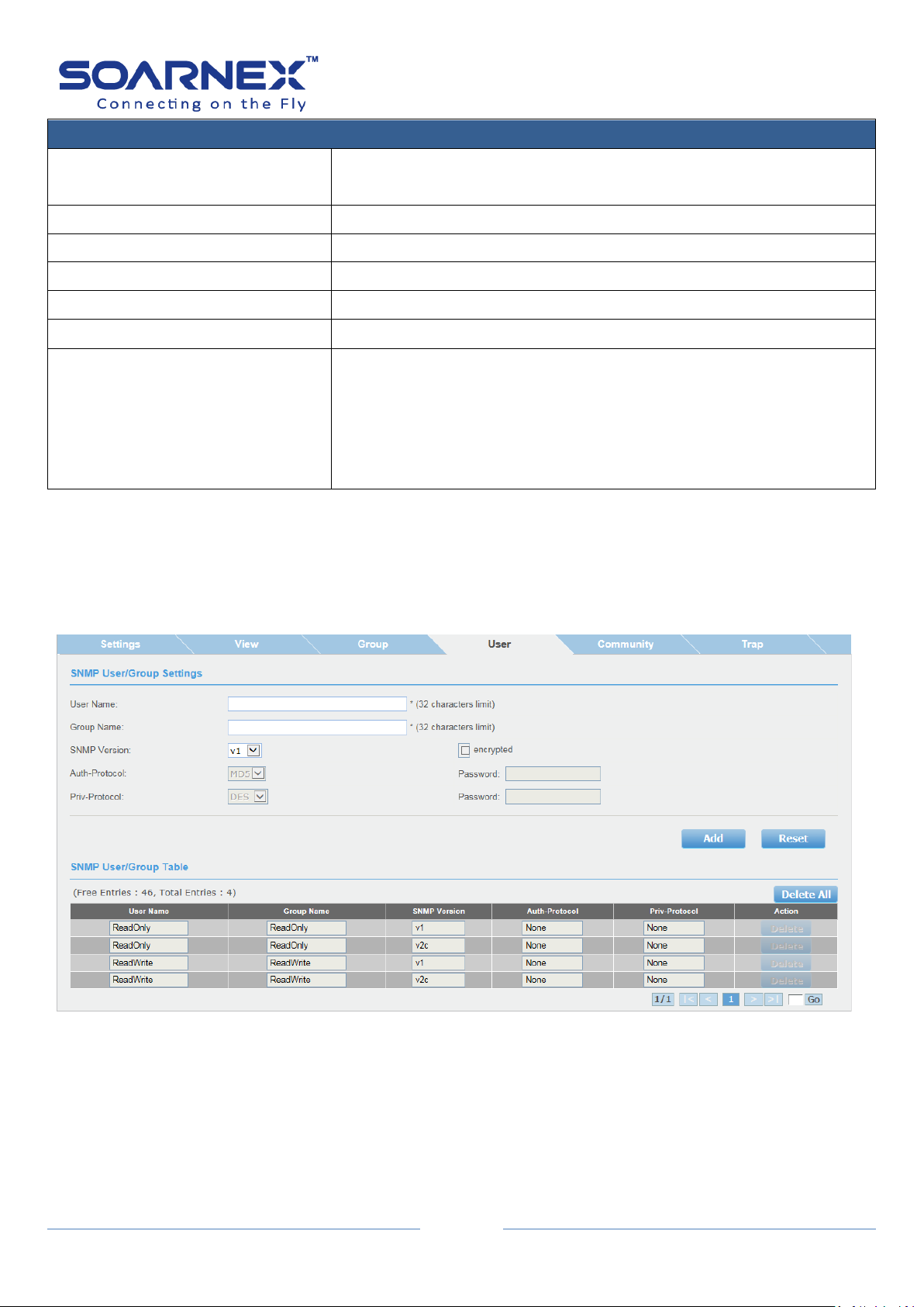
2-13-4. User
An SNMP User Name and Group Name definition are the basic information
for all SNMP tables.
Figure 5-2-13-4 SNMP – User/Group Settings

EG210 Series L2+ Smart Managed Switch
42
SNMP User/Group Settings
User Name
Enter a User Name which range is from 1 to 32 characters.
Group Name
Enter a Group Name which range is from 1 to 32 characters.
SNMP Version
Click pull-down list to select SNMP version (v1, v2c or v3).
The encryption check-box becomes active when user has selected
SNMP version to v3.
Auto-Protocol
When user has selected SNMP version of v3 and enable encrypted,
the Auth-Protocol can be chose either MD5 or SHA.
MD5:
SNMP User is authenticated with the MD5 authentication protocol
after a piece of message is received.
The password range is from 1 to 46.
SHA:
User is authenticated with the SHA authentication protocol after a
piece of message is received.
The password range is from 1~46.
Priv-Protocol
When user has selected SNMP version of v3 and enable encrypted,
the Priv-Protocol can be chose either DES or None.
DES:
Specify DES encryption scrambles the SNMP data so that outside
observers are prevented from seeing the data content.
None:
Specify no encryption is applied to SNMP data.
The password ranges is 1~46.
SNMP User/Group Table
User Name
To display each SNMP User Name information.
Group Name
To display each Group User Name information.
SNMP Version
To display each entry SNMP version.
Auto-Protocol
To display each entry SNMP Auto-Protocol type (MD5 or SHA).
Priv-Protocol
To display each entry SNMP Priv-Protocol type (DES or NONE).
Action
User can click Delete button for the User Name and Group Name that
he wants to remove it.
If user needs to modify an entry on the SNMP User/Group page, first
he must delete the entry and after re-enter it.
The ReadOnly and ReadWrite Group Names are default values and
they cannot be removed.
User Manual

EG210 Series L2+ Smart Managed Switch
43
SNMP Community Settings
Community Name
The Name of the community string.
By default, the Switch creates two Community Name, “Public” for
ReadOnly and “Private” for ReadWrite.
The Community Name string range is from 1 to 32 and the maximum
community size is 10.
User Name (View Policy)
Enter the SNMP User Name. Go to SNMP User/Group page to add it.
Note: The User Name must pre-defined on the SNMP User/Group
page
SNMP Community Table
Community Name
Display each Community entry.
User Name (View Policy)
Display each Community entry assigned User Name.
Action
User click “Delete” button to remove each Community entry.
2-13-5. Community
The community name acts as a simple authentication mechanism to restrict
the machines in the network to request data from the SNMP agent. The name
functions as a password, and user’s request was assume to be authorized if
the sender knew the password.
The community name can be in any alphanumeric format. Double quote (") is
not a valid character.
User Manual
Figure 5-2-13-5 SNMP – Community Settings
44
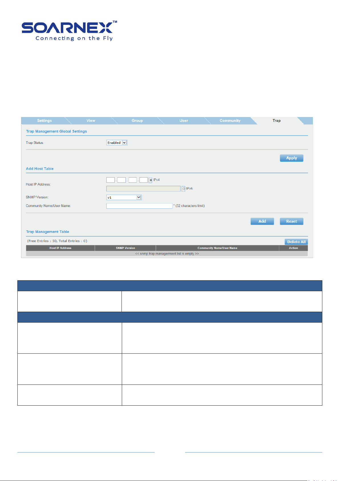
2-13-6. Trap
Trap Management Settings
Trap
User can Enable or Disable Trap management here.
By default, trap management is Enabled.
Add Host Table
Host IP Address
Enter the Host IP Address to receive the SNMP traps, the Host IP
Address supports IPv4 Address, Global IPv6 Address or IPv6 Link-Local
Address.
SNMP Version
Click pull-down list to select SNMP version (v1, v2c, v3-NoAuthNoPriv,
v3-AuthNoPriv and v3-AuthPriv)
That is configured for the host management device.
Community Name/User Name
Enter a Community Name that user has added in the SNMP
Community table. (32 characters limit)
A Host IP address is used to specify a management device that needs to
receive SNMP traps sent by the Switch. This IP address is associated with the
SNMP Version and a valid Community Name in the Host table of the Switch.
Please specify whether the device can send SNMP notifications or not
EG210 Series L2+ Smart Managed Switch
User Manual
Figure 5-2-13-6 SNMP – Trap Management Global Settings
45
Trap Management Table
Host IP Address
Display each Trap Management entry assigned Host IP Address.
SNMP Version
Display each Trap Management entry assigned SNMP version.
Community Name/User Name
Display each Trap Management entry assigned Community Name.
Action
User can click Delete button to remove Trap Management entry.
If user needs to modify an SNMP Trap entry, first he must delete the
entry and then re-enter it with the modification by creating a new
SNMP trap.
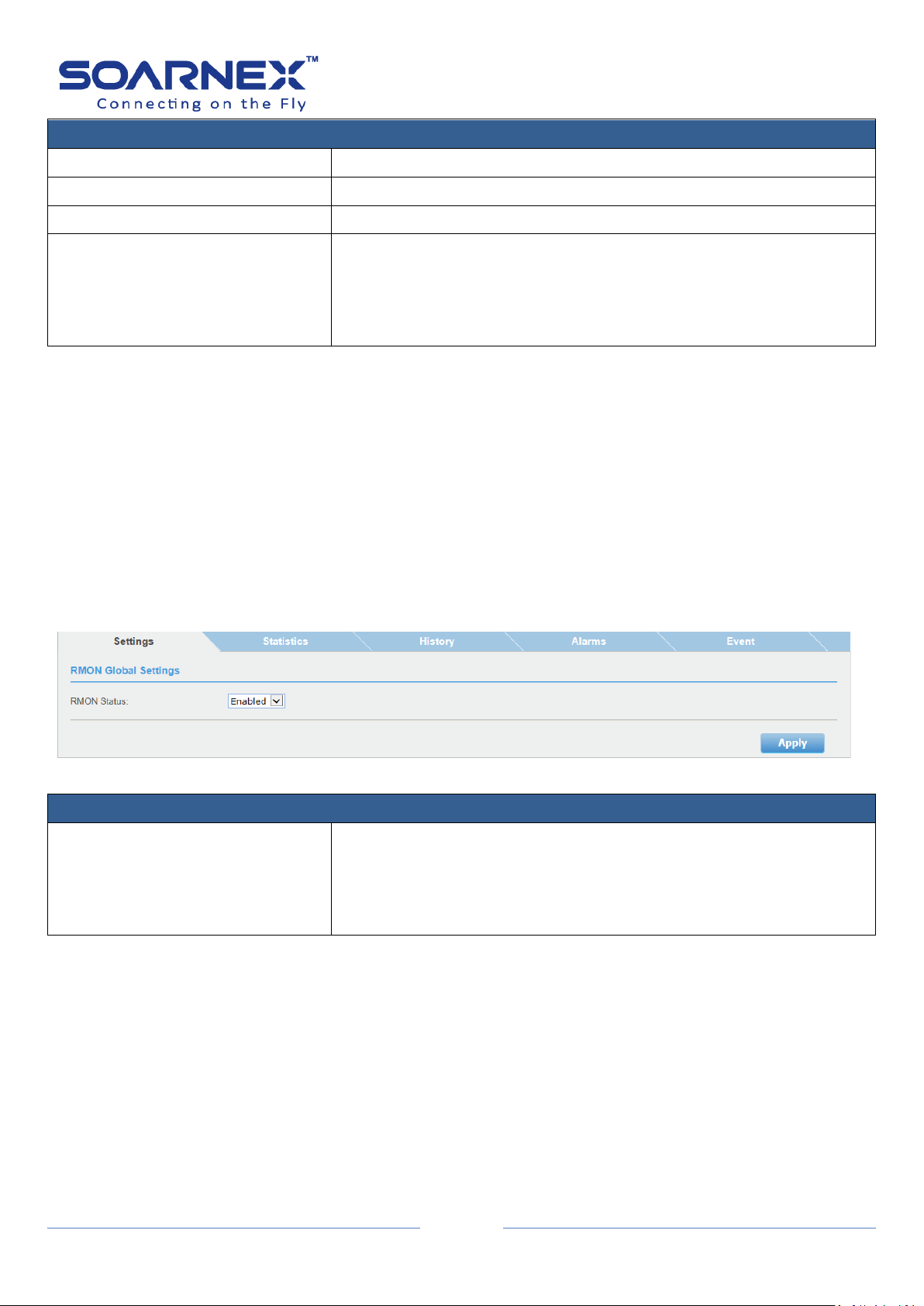
RMON Global Settings
RMON Status
Click pull-down list to enable or disable RMON feature.
The default value is Disabled.
Note: User has to enable the SNMP agent. If he would like to use the
RMON function.
2-14. RMON
EG210 Series L2+ Smart Managed Switch
User Manual
The RMON (Remote Monitoring) is used with SNMP applications to support monitoring and
protocol analysis of LANs. User can use SNMP management tools and RMON section of the
MIB tree to view the RMON statistics, history and alarm associated with switch ports.
2-14-1. Settings
Figure 5-2-14-1 RMON – Global Settings
EG210 Series L2+ Smart Managed Switch
46
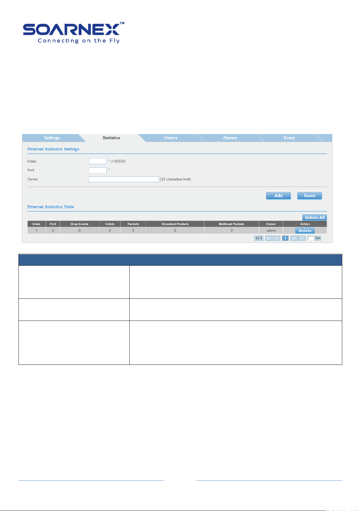
Ethernet Statistics Settings
Index
Enter an ID number for the special port to view an individual port
statistics.
Its range is from 1 to 65535
Port
Enter the port number that user wants to monitor the statistical
information in the Ethernet traffic.
Owner
Enter an owner’s name which can be one or many (e.g. IP address,
management station name, network manager’s name, location, or
phone number). The owner is an optional field.
Its range is from 0 to 32.
2-14-2. Statistics
User can set a special port to view an individual port statistics on the RMON
Ethernet Statistics Settings page.
The RMON Ethernet statistics have measured by the probe for each
monitored Ethernet interface on this switch.
This group consists of the RMON Ethernet Statistics Table.
User Manual
Figure 5-2-14-2 RMON – Ethernet Statistics Settings

EG210 Series L2+ Smart Managed Switch
47
Ethernet Statistics Table
Index
Display Index number of the special port that you’ve created to
monitor the statistical information in the Ethernet traffic.
Port
Display the port number.
Drop Events
Display port ethStatsDropEvents information on the special port
which user has assigned it
User also could use SNMP management utility to monitor the
RMON-MIB tree to get “ethStatsDropEvents” information.
Octets
Display port ethStatsOctets information on the special port which
user has assigned it
User also could use SNMP management utility to monitor the
RMON-MIB tree to get “ethStatsOctets” information.
Packets
Display port ethStatsPkts information on the special port which user
has assigned it.
User also could use SNMP management utility to monitor the
RMON-MIB tree to get “ethStatsPkts” information.
Broadcast Packets
Display port ethStatsBroadcastPkts information on the special port
which user has assigned it.
User also could use SNMP management utility to monitor the
RMON-MIB tree to get “ethStatsBroadcastPkts” information.
Multicast Packets
Display port ethStatsMulticastPkts information on the special port
which user has assigned it
User also could use SNMP management utility to monitor the
RMON-MIB tree to get “ethStatsMulticastPkts” information.
Owner
Display an owner’s information which he has created it.
Action
User can click Delete button to delete created entry.
User Manual

EG210 Series L2+ Smart Managed Switch
48
History Control Settings
Index
Enter an ID number for the RMON History Control Settings.
Its range is from 1 to 65535.
Port
Enter the port number that you want to control the statistics history.
Buckets Requested
The number of snapshots of the statistics for the special port. Each
bucket can store one snapshot of RMON statistics.
Different ports can have different numbers of buckets.
Its range is from 1 to 50 buckets.
Interval
The interval is how frequently the switch has been taken the
snapshots of the port’s statistics.
Its range is from 1 to 3600 seconds (1 hour).
Owner
Enter the owner’s name.
2-14-3. History
User can use the RMON history to modify and to see how many of these
historical entries are saved in buckets as well as how often their intervals are
taken. He can modify the sampling interval and the buckets (the number of
entries saved before overwrite).
Note: User also needs to enable SNMP agent, RMON feature and set RMON
Ethernet Statistics for the special port assigned.
User Manual
Figure 5-2-14-3 RMON – History Control Settings

49
History Control Table
Index
Display Index number of RMON History Control entry that user has
added it.
Port
Display the port number.
Buckets Requested
Display the number of buckets requirements that user has created
in RMON History Control entry.
Buckets Granted
Display the number of buckets allocated by the Switch for the history
group.
Interval
Display the polling interval in seconds that user has configured in
RMON History Control entry.
Owner
Display an owner’s information that user has created.
Action
User can click Delete button to delete created entry.
2-14-4. Alarm
EG210 Series L2+ Smart Managed Switch
User Manual
The RMON Alarm Settings allows user to configure the network alarms, the
Switch generates alarm message when packet activity on designated ports
rises above or falls below specified threshold values. The alarm messages can
enter in the event log on the switch or send SNMP traps to your SNMP
management utility.
The RMON statistic (The frequency with which the switch samples the
thresholds) is controlled by a time interval parameter.
There are two thresholds for the RMON alarm settings: A Rising threshold and
a Falling threshold.
The alarm is triggered if the value of the monitored RMON statistic of the
designated port exceeds the rising threshold.
The alarm would reset if the value of the monitored statistic dropped below
to the falling threshold.
The RMON alarm has three different components: RMON Ethernet Statistics,
RMON Alarm and RMON Event.
Follow up the listed steps to complete a port RMON alarm setting:
1. Create an entry for the special port on RMON Ethernet Statistics page.
2. Create an entry for the special port and configure the alarm settings.
3. Create an index number on the RMON Event page, the index number for
Rising Event or Falling Event index that user has configured in RMON alarm
entry.

EG210 Series L2+ Smart Managed Switch
50
RMON Alarm Settings
Index
Enter an ID number for the RMON alarm Settings.
Its range is from 1 to 65535.
Interval
Enter the time period (in seconds) which data is sampled
Alarm interval range should be from 1 to 2147483647 seconds.
Variable
Specify the SNMP MIB object Identifier (OID) to monitor the switch
events.
Sample Type
This parameter defines what type of changes would trigger the alarm
to monitor the statistics. There are two types of the Sample Type
filed: One is the Delta value and the other is the Absolute value. The
default is Absolute value.
Delta value:
Setting compares a threshold against the difference between the
current and previous values of the statistic.
Absolute value:
Setting compares a threshold against the current value of the statistic
Click pull-down list to choose the Delta value or the Absolute value.
Rising Threshold
Specify a special value of the Rising threshold to monitor statistics,
when the monitored statistics become bigger than the threshold and
then an alarm event will be triggered.
The range of the Rising Threshold should be from 1 to 2147483647
User Manual
Figure 5-2-14-4 RMON – Alarm Settings

EG210 Series L2+ Smart Managed Switch
51
seconds
Falling Threshold
Specify a special value of the Rising threshold to monitor statistics,
when the monitored statistics become smaller than the threshold,
and then an alarm event will be triggered.
The range of the Falling Threshold should be from 1 to 2147483647
seconds
Note: The Falling Threshold value should be smaller than the Rising
Threshold value
Rising Event Index
Specify the Event Index for the Rising Threshold.
You must create the Event Index number before you add an RMON
Alarm entry. Its range is from 1 to 65535.
Falling Event Index
Specify the Event Index for the Falling Threshold.
You must create Event Index number before you add an RMON Alarm
entry. Its range is from 1 to 65535.
Owner
Enter the owner’s name. (32 characters limit)
RMON Alarm Table
Free Entries
Display free entries that you’ve created for the RMON alarm.
Total Entries
Display created entries in the RMON alarm.
Action button
Delete All:
User can click “Delete All” button to delete created entries at the
same time.
Delete:
User can click “Delete” button to delete created entry.
Index
Display the index ID number.
Interval
Display the alarm interval value in second.
Variable
Display the SNMP MIB object Identifier (OID).
Sample Type
Display the sample type.
Rising Threshold
Display the Rising Threshold value in second.
Falling Threshold
Display the Falling Threshold value in second.
Rising Event Index
Display the Rising Event Index number.
Falling Event Index
Display the Falling Event Index number.
Owner
Display the owner’s name.
Action
User can click “Delete” button to delete created entry.
User Manual

52
2-14-5. Event
RMON Event Settings
Index
Enter an ID number for the RMON Event Index.
Its range is from 1 to 65535.
Description
Enter a text description of the Event that you configure.
Type
Click pull-down list to select where and what type of events which need to be sent
when the trigger is occurred. User can set log a message in the Event Log of the
switch, generator a SNMP trap to SNMP management utility, or both (Log and Trap).
Community
Specify the Community Name that you want to send the SNMP Trap.
Owner
Enter the owner’s name.
Figure 5-2-14-5 RMON – Event Settings
EG210 Series L2+ Smart Managed Switch
User Manual

53
RMON Event Table
Free Entries
Display free entries that you’ve created for the RMON Event Index.
Total Entries
Display created entries in the RMON Event Index.
Action button
Delete All:
User can click “Delete All” button to delete created entries at the
same time.
Delete:
User can click “Delete” button to delete created entry.
2-15. Statistics
Traffic Information
Port ID
Display port number on the Switch.
InOctets
Display Inbound Octets (Bytes/s), number of inbound octet bits in
bytes per second.
InUcastPkts
Display Inbound Unicast Packets (Pkts), number of inbound Unicast
packets in packets per second.
Statistics provide detailed information for counter at the port level; and the administrator
can check this information to troubleshooting the connection problems.
Besides, the Switch can offer two statistics charts. One is Traffic Information and the other is
Error Information.
EG210 Series L2+ Smart Managed Switch
User Manual
2-15-1. Traffic
Figure 5-2-15-1 Statistics – Traffic Information
EG210 Series L2+ Smart Managed Switch
54
InNUcastPkts
Display Inbound Non-Unicast Packets (Pkts), number of inbound
non-Unicast packets (such as broadcast and multicast packets) in
packets per second
InDiscards
Display Inbound Discards (Pkts), number of inbound discarded
packets in packets per second.
OutOctets
Display Outbound Octets (Bytes/s), rate of outbound octet bits in
bytes per second.
OutUcastPkts
Display Outbound Unicast Packets (Pkts), number of outbound
Unicast packets in packets per second.
OutNUcastPkts
Display Outbound Non-Unicast Packets (Pkts), number of outbound
non-Unicast (such as broadcast and multicast packets) packets.
OutDiscards
Display Outbound Discards (Pkts), number of outbound discarded
packets.
Clear
User can click Apply button for Clear this port counter information.
Refresh
User can click Refresh button to renew the values.
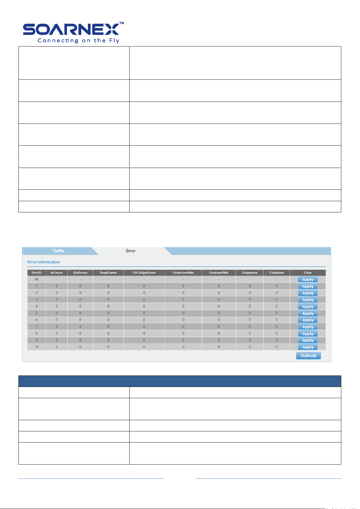
Traffic Information
Port ID
Display port number on the switch.
InErrors
Display Inbound Errors (Pkts), number of inbound errors in packets
per second.
OutErrors
Display Outbound Errors (Pkts), number of outbound error packets.
DropEvents
Display Drop Events, number of packets dropped.
CRCAlignErrors
Display CRC and Align Errors, number of CRC and Align errors when
occurred.
User Manual
2-15-2. Error
Figure 5-2-15-2 Statistics – Error Information
EG210 Series L2+ Smart Managed Switch
55
UndersizePkts
Display Undersize Packets (Pkts), number of undersized packets (less
than 64 octets) received.
OversizePkts
Display Oversize Packets (Pkts), number of oversized packets (over
2000 octets) received.
Fragments
Display Number of fragments (packets with less than 64 octets,
excluding framing bits, but including FCS octets) received.
Collisions
Display Number of collisions received. If Jumbo Frames are enabled,
the threshold of Jabber Frames is raised to the maximum size of
Jumbo Frames.
Clear
User can click Apply button to Clear this port counter information.
Refresh
User can click Refresh button to renew the values.
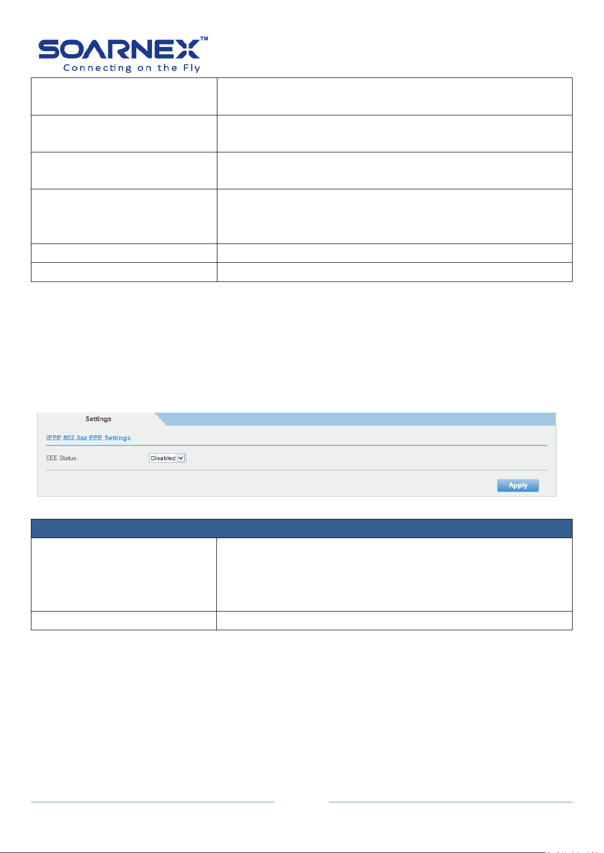
IEEE 802.3az EEE Settings
EEE Status
Click pull-down list to Enable or Disable IEEE 802.3az Energy Efficient
Ethernet feature.
By default, the Switch has disabled the IEEE 802.3az EEE function.
User can enable this feature via the IEEE802.3az EEE setting page.
Apply button
User can click Delete button to delete created entry.
2-16. IEEE 802.3az EEE
The IEEE 802.3az Energy Efficient Ethernet (EEE) standard has intended to reduce the energy
User Manual
used by an Ethernet device during low utilization period, by transitioning interfaces into a
low-power state without interrupting the network connection.
Note: The transmitted and received sides should be IEEE 802.3az EEE compliance.
Figure 5-2-16 IEEE 802.3az EEE

56
3. Network
Physical Interface
Port
This column shows the port numbers.
The All value indicates all the ports on the Switch.
For the combo ports (RJ-45/SFP) only one interface will be activated
at the same time. Three are medias will be displayed as
Port_number(1), Port_number(2) and port_number(3) ,which 1, 2, 3
is indicated to media type:
(1) =copper; (2)=100-fiber and (3)=1G-fiber and they are able to set
individually.
Trunk
This column shows the trunk status with trunk group number.
A number in this column shows which port number has been added
to a trunk using static or dynamic 802.3ad LACP link aggregation.
3-1. Physical Interface
This Physical Interface page allows user to configure the physical port settings including
admin status, network speed, duplex mode, jumbo frames, flow control, EAP setting and
BPDU packet forwarding.
This page also shows current trunk status, link status and negotiated type information. On
each port
Additionally, user will be able to set up his BPDU ports for Spanning Tree, Configuration and
EAP ports for 802.1X port-based authentication configuration.
EG210 Series L2+ Smart Managed Switch
User Manual
Figure 5-3-1 Physical Interface

EG210 Series L2+ Smart Managed Switch
57
Type
This column shows the port type.
For example, On the Switch, the port type is:
1000TX for 10/100/1000Base-T twisted-pair ports (1-48)
100FX or 1000X for the SFP ports (45F-48F) for copper or fiber SFP
type.
Link Status
This column shows the network link status on each port.
The possible values are:
Up: This value indicates a valid link exists between the port and the
end node.
Down: This value indicates the port and the end node have not
established a valid link.
Admin. Status
Use the drop-down menu to specify the port to be enabled or
disabled.
Note:
User may want to disable a port and to prevent packets from
being forwarded if a problem occurred with the node or cable
connected to the port.
User can enable the port to resume it to normal operation after
the problem has been fixed.
User also can disable an unused port for security reason to
secure no link from unauthorized connections.
All Ports:
If user selects Ignore and clicks on Apply for all ports, the Admin
Status is not changed.
If user selects Enabled then clicks on Apply for all ports, the Admin
Status on all ports will be set to be Enabled.
Each Port:
Enabled: This port is enabled to send and receive Ethernet frames.
Disabled: This port is disabled and cannot send and receive
Ethernet frames.
Note: Click Apply to apply for the changes.
User Manual

EG210 Series L2+ Smart Managed Switch
58
Mode
Use the drop-down menu to specify the auto-negotiation
configuration
All Ports:
If user selects Ignore and clicks on Apply for all ports, the Mode is not
changed.
If user sets to Auto mode then clicks on Apply for all ports, the Mode
on all ports will be set to the same value.
Each Port:
Auto: This parameter indicates the port is using Auto-Negotiation to
set the operating speed and duplex mode. The actual operating speed
and duplex mode of the port are displayed in parentheses (for
example, “1000F”for 1000 Mbps full duplex mode) after a port
establishes a link with an end node.
Auto: This parameter indicates the port is configured to operate
Auto-Negotiation mode.
1000/Full: This parameter indicates the port is configured to
operate 1000Mbps full-duplex mode.
100/Full: This parameter indicates the port is configured to
operate 100Mbps full-duplex mode.
10/Full: This parameter indicates the port is configured to
operate 10Mbps full-duplex mode.
100/Half: This parameter indicates the port is configured to
operate 100Mbps half-duplex mode.
10/Half: This parameter indicates the port is configured to
operate 10Mbps operation in half-duplex mode.
Note:
When user selects a Mode setting, the following points need to be
applied for:
When a twisted-pair port is set to Auto-Negotiation, the end
node should also be set to Auto-Negotiation to prevent a duplex
mode mismatch.
The only valid setting for the SFP ports is Auto-Negotiation.
Note: Click Apply to apply for the changes.
User Manual

EG210 Series L2+ Smart Managed Switch
59
Jumbo
Use the drop-down menu to enable or disable the Jumbo Frame
function on the Switch.
The default is Disabled. Max. Jumbo frame size = 10000 bytes if this is
enabled.
This parameter indicates whether the jumbo frames can be accepted
by the Switch or not.
All Ports:
If user selects Ignore and clicks on Apply for all ports, the Jumbo
setting is not changed.
If user selects Enabled or Disabled then clicks on Apply for all ports,
Jumbo setting on all ports will be set to the same value on Enabled or
Disabled.
Each Port:
Enabled: This port is enabled to send and receive Jumbo frames.
Disabled: This port is disabled and cannot send and receive Jumbo
frames.
Note:
Click Apply to apply for the changes.
When QoS is enabled the Jumbo frame parameter cannot be
enabled.
Flow Control
Use the drop-down menu to enable or disable the Flow Control
function on the Switch.
Note:
Ports stay in full-duplex use 802.3x flow control (PAUSE frame)
Ports stay in half-duplex ports use backpressure flow control
All Ports:
If user selects Ignore and clicks on Apply for all ports, the Flow
Control setting is not changed.
If user selects Enabled or Disabled then clicks on Apply for all ports,
Flow Control setting on all ports will be set to the same value on
Enabled or Disabled.
Each Port:
Enabled: This port is enabled the flow control function.
Disabled: This port is disabled and won’t run the flow control
function.
Note: Click Apply to apply for the changes.
User Manual

EG210 Series L2+ Smart Managed Switch
60
EAP PassThrough
Use the drop-down menu to enable or disable the Extensible
Authentication Protocol (EAP) setting on the port.
All Ports:
If user selects Ignore and clicks on Apply for all ports, the EAP setting
is not changed.
If user selects Enabled or Disabled then clicks on Apply for all ports,
EAP setting on all ports will be set to the same value on Enabled or
Disabled.
Each Port:
Enabled: This port is enabled to send and receive EAP packets.
Disabled: This port is disabled and will not send and receive EAP
packets.
Note: Click Apply to apply for the changes
BPDU PassThrough
Use the drop-down menu to enable or disable the current BPDU
setting on the port.
All Ports:
If user selects Ignore and clicks on Apply for all ports, the BPDU
setting is not changing.
If user selects Enabled or Disabled then clicks on Apply for all ports,
BPDU setting on all ports will be set to the same value on Enabled or
Disabled.
Each Port:
Enabled: This port is enabled to pass BPDU frames through the
Switch and broadcast them through all other ports.
Disabled: This port is disabled and the Switch will not pass BPDU
frames through the Switch.
With RSTP or STP enabled, the Switch will receive BPDU frames and
process them by the spanning tree protocol.
Note: Click Apply to apply for the changes.
Port Description
Enter the description for this port (32 characters limit)
User Manual

61
3-2. Spanning Tree
There are three versions of the Spanning Tree Protocol: 802.1d STP, 802.1w RSTP, 802.1s
MSTP.
Spanning Tree Protocol (STP): Provides a single path between end stations, and to avoid and
to eliminate the network loops.
Rapid Spanning Tree Protocol (RSTP): Detects and uses of network topologies that provides
faster spanning tree convergence without creating any forwarding loops.
Multiple Spanning Tree Protocol (MSTP): Defines an extension to RSTP to further develop
the usefulness of virtual LANs (VLANs). This "Per-VLAN" Multiple Spanning Tree Protocol
configures a separate Spanning Tree for each VLAN group and blocks all but one of the
possible alternate paths within each Spanning Tree.
3-2-1. Protocol
EG210 Series L2+ Smart Managed Switch
User Manual
The Spanning Tree – Protocol Settings page allows users to enable/disable Global
STP Status, to select STP Protocol version (STP, RSTP or MSTP), and to set up Bridge
Priority and other parameters of STP (Maximum Age, Hello Time, Forward Delay,
Transmit Hold Count and Max Hop Count).
Figure 5-3-2-1 Spanning Tree – Protocol

EG210 Series L2+ Smart Managed Switch
62
Spanning Tree Protocol Settings
Global STP Status
Use the drop-down menu to select the STP state on the device.
Disable: Disables STP on the device. This is the default value.
Enable: Enables STP on the device.
Note. To Enable Global STP status, BPDU should be disabled (Bridge
-> Go to Physical Interface page to enable/disable BPDU).
Protocol Version
Use the drop-down menu to select the Spanning Tree Protocol (STP)
mode.
STP: Enables STP 802.1D on the device.
RSTP: Enables Rapid STP 802.1w on the device. This is the default
value.
MSTP: Enables Multiple STP 802.1s on the device.
Bridge Priority
Use the drop-down menu to select the Bridge Priority which has a
range from 0 to 61440 in increments of 4096. The default value is
32768. Specify the Priority value assigned to the bridge that is used to
be the Root Bridge. Control the bridge priority: the lower numeric
values have higher priority.
Maximum Age
The Maximum Age defines how long that a port will wait for STP/RSTP
information. MSTP uses this parameter when it’s interacting with
STP/RSTP domains on the boundary ports.
Its range is from 6 to 40 seconds
Hello Time
The Hello Time is frequency with which the root bridge sends out a
BPDU. Its range is from 1 to 10 seconds
Forward Delay
The Forward Delay defines the time that the bridge spends the
listening and learning states.
Its range is from 4 to 30 seconds.
Transmit Hold Count
The Transmit Hold Count specifies the maximum number of BPDUs
that the bridge can send per second. When exceeded, transmission of
the next BPDU will be delayed.
Its range is from 1 to 10 BPDU's per second..
Max Hop Count
This defines the initial value of remaining Hops for MSTI information
generated at the boundary of an MSTI region. It defines how many
bridges can distribute its BPDU information. When the Hop Count
value reaches zero, the bridge drops the BPDU packet.
Its range is from 6 to 40 hops.
User Manual
Note, The STP Global Settings must follow standard rule: 2*(Forward Delay -1) >= Max Age >= 2*(Hello
Time+1)
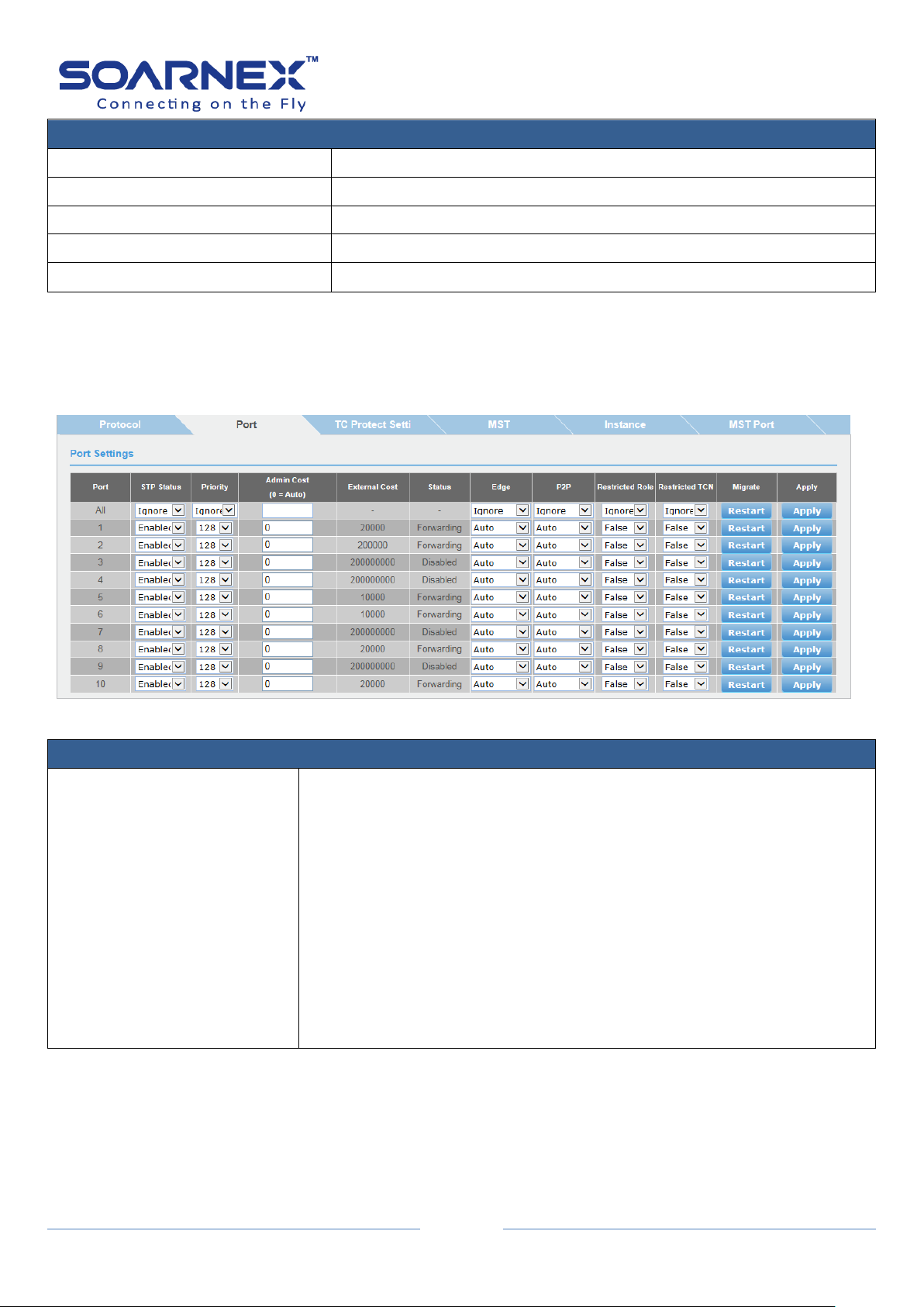
63
Root Information
Root Bridge
The root bridge ID in the spanning tree.
Root Cost
The connection cost on the root port Root.
Root Maximum Age
The aging timeout for the root port.
Root Forward Delay
The forward delay timer before packet forwarding.
Root Port
The port number has been assigned as root port.
3-2-2. Port
Port Settings
STP Status
Use the drop-down menu to select spanning tree protocol and to active
or inactive it on each port.
All Ports: If you select Ignore and click on Apply for all ports, the STP
Status setting is not changed.
If you select Enabled or Disabled then click on Apply for all ports, STP
Status setting on all ports will be set to the same value on Enabled or
Disabled.
Each Port: Enable: The spanning tree protocol is enabled on the port.
Disabled: The spanning tree protocol is disabled on the port.
Note: Click Apply to apply for the changes.
STP can be set up based on each port.
EG210 Series L2+ Smart Managed Switch
User Manual
Figure 5-3-2-2 Spanning Tree - Port

EG210 Series L2+ Smart Managed Switch
64
Priority
Use the drop-down menu to select port priority.
Its range is from 0 to 240. Port bridge priority setting number is multiple
of 16
All Ports: If you select Ignore on All Ports and click on Apply for all ports,
the Admin Cost setting is not changing.
If you set up the value and then click on Apply for Enter a value between
0 and 240 to set the priority for the port interface.
This can be used to control priority of ports having identical port cost
Indicates the port priority.
If two paths have the same port cost, the bridge must select a preferred
path. In this case, it can involve with the use of the port priority
parameter which is used as a tie breaker when two paths have the same
cost.
A higher priority is designated to let the interface to forward the packets
first. The lower number means the higher priority.
Note: Click Apply to apply the change.
User Manual

EG210 Series L2+ Smart Managed Switch
65
Admin Cost
(0 = Auto)
The Admin Cost controls the path cost incurred by the port. The
default values is 0 = Auto.
Writing a value of '0' = Auto setting will set the path cost as
appropriate by the physical link speed, using the 802.1D
recommended values.
Link speed Recommended value
100Kb/s 200,000,000
1 Mb/s 20,000,000
10 Mb/s 2,000,000
100 Mb/s 200,000
1 Gb/s 20,000
10 Gb/s 2,000
100 Gb/s 200
1 Tb/s 20
10 Tb/s 2
Using the Specific setting, a user-defined value can be entered.
The path cost is used when establishing the active topology of the
network. Lower path cost ports are chosen as forwarding ports in
favor of higher path cost ports.
Its range is 0 - 200000000
External Cost
This defines a metric that indicates the relative cost of forwarding
packets to the specified port list.
Port cost can be set automatically or as a metric value.
Define a value between 1 and 200,000,000 to determine the external
cost.
The default value is 20000.
User Manual

EG210 Series L2+ Smart Managed Switch
66
State
Displays the current port spanning tree state.
Discarding:
A discarding state does not allow network traffic to be sent or
received on the port except for BPDU data.
A port with a higher path cost to the root bridge than another on the
switch causes a switching loop and is placed in the discarding state by
the Spanning Tree algorithm. The port’s state may change to the
forwarding state if the other links in use fail and the Spanning Tree
algorithm determines the port may transition to the forwarding state.
Learning:
While the port does not yet forward frames (packets), in this state the
port does learn source addresses from frames received and adds
them to the filtering (switching) database.
Forwarding:
A port that both receives and sends data. This indicates normal
operation. STP continues to monitor the port for incoming BPDUs
that indicate the port should return to the blocking state to prevent a
loop. Disabled:
A port with STP disabled does not participate in STP. A network
administrator can manually disable a port.
Edge
Indicates the port which is connected to an edge device in the
network topology or not.
Selecting the Auto parameter indicates that the port has edge port
status or not has edge port status automatically.
The default setting for this parameter is Auto.
Selecting the ForceTrue to assign the port as an edge port. Edge ports
cannot create loops, however an edge port can lose edge port status
if a topology change creates a potential for a loop.
An edge port normally should not receive BPDU packets.
If a BPDU packet is received, it automatically loses edge port status.
Selecting the ForceFalse indicates that the port does not has edge
port status.
If you select Ignore on All Ports and click on Apply for all ports, the
Admin Cost setting is not changing.
If you set the value then click on Apply for all ports, The Admin Cost
will be set to the same value.
Note: Click Apply to apply for the changes.
User Manual

EG210 Series L2+ Smart Managed Switch
67
P2P
Choosing the Auto parameter, allows the port to has P2P status
whenever possible and operates as if the P2P status were true.
The default setting for this parameter is Auto.
Choosing the Forcetrue parameter indicates a point-to-point (P2P)
shared link. P2P ports are similar to edge ports however they are
restricted in that a P2P port must operate in full-duplex. Like edge
ports, P2P ports transition to a forwarding state rapidly thus
benefiting from RSTP.
Choosing the Forcefalse parameter indicates that the port cannot has
P2P status.
If the port cannot maintain this status, (for example if the port is
forced to half-duplex operation) the P2P status changes to operate as
if the P2P value were Forcefalse.
Restricted Role
Toggle between True and False to set the restricted role state of the
packet.
If set to True, the port will never be selected as the Root port.
The default value is False.
Restricted TCN
Topology Change Notification (TCN) is a BPDU that a bridge sends
out a topology signal changes to its root port.
Toggle between True and False to set the restricted TCN of the
packet.
If set to True, it stops the port from propagating received TCN and to
other ports.
The default value is False.
Migrate
Indicates the port which is configured to accept RSTP and STP BPDUs.
Click Reset button is set the ports to send out BPDU packets to other
bridges, requesting information on their STP setting.
If the Switch is configured for RSTP, the port will be capable to
migrate from 802.1d STP to 802.1w RSTP.
Migration should be Reset on ports connected to network stations or
segments that are capable of being upgraded to 802.1w RSTP on all
or some portion of the segment.
User Manual
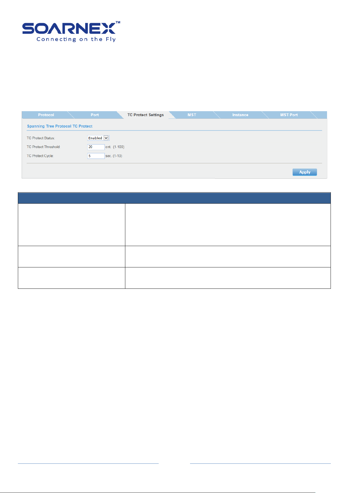
EG210 Series L2+ Smart Managed Switch
68
Spanning Tree Protocol TC Protect Settings
TC Protect Status
Use the drop-down menu to select the TC Protect status on the
device.
Disable: Disables TC Protect on the device. This is the default value.
Enable: Enables TC Protect on the device.
TC Protect Threshold
Enter the maximum number of TC-BPDUs are received in a TC protect
cycle. Its range is 1 – 100. Default value is 20.
TC Protect Cycle
Enter a value of the seconds for a TC protect cycle.
Its range is 1 – 10 second. Default value is 5 seconds.
3-2-3. TC Protect Settings
The TC protect as a spanning tree security function. The TC protect function to
prevents received lot of TC-BPDUs to affecting the network in a short time and
prevents frequent flushing the forwarding table.
Figure 5-3-2-3 Spanning Tree – TC Protect
User Manual
3-2-4. MST
Multiple Spanning Tree Protocol(MSTP) that allows one or multiple VLANs maps to
a single Spanning Tree Instance (STI), the MSTP provides load balancing and faster
convergences.
For example, a switch port might be dynamically blocked in one Spanning Tree
Instance, but the same port can be placed in forwarding state in other Spanning
Tree Instance.
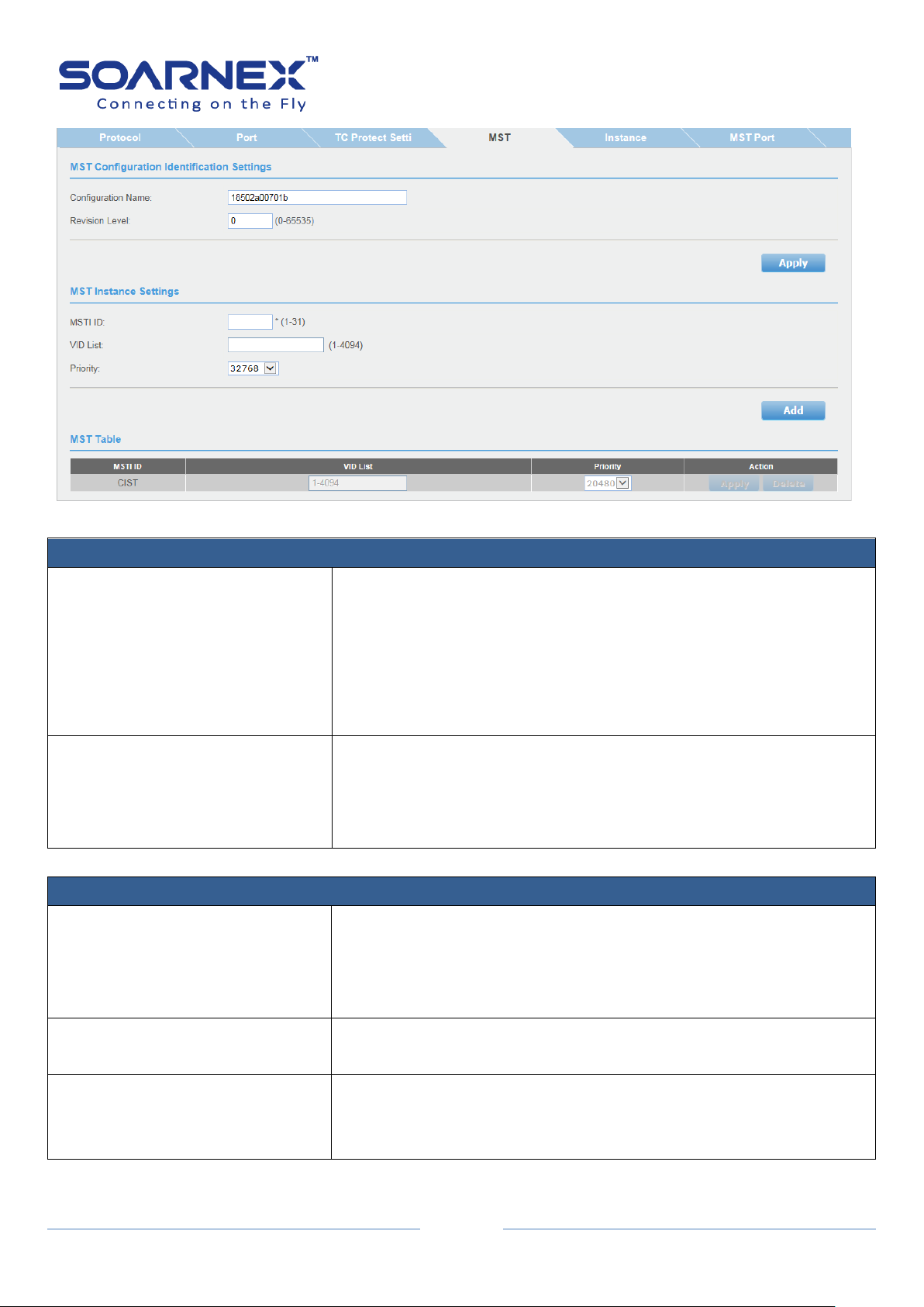
EG210 Series L2+ Smart Managed Switch
69
MST Configuration Identification Settings
Configuration Name
The Bridges must share the name and Revision, as well as the
VLAN-to-MSTI mapping configuration in order to share spanning trees
for MSTI's.
The name is at most 32 characters.
If a configuration name is not set, this field shows the MAC address of
the device running MSTP.
Revision Level
This value, together with the configuration name, and identical VLAN
mapped for STP instance IDs identifies the MST region configured on
the switch.
This must be an integer between 0 and 65535.
MST Instance Settings
MSTI ID
An MSTI ID will classify these instances
The MSTI IDs currently set on the Switch, the MSTI ID is associated
with the VLAN ID.
Its range is from 1 to 31.
VID List
The VLAN IDs is associated with the specific MSTI.
Its Range is from 1 to 4094.
Priority
Use the drop-down menu to select the Bridge Priority which has a
range from 0 to 61440 in increments of 4096.
The user may set a priority value between 0 and 61440.
Figure 5-3-2-4 Spanning Tree - MST
User Manual
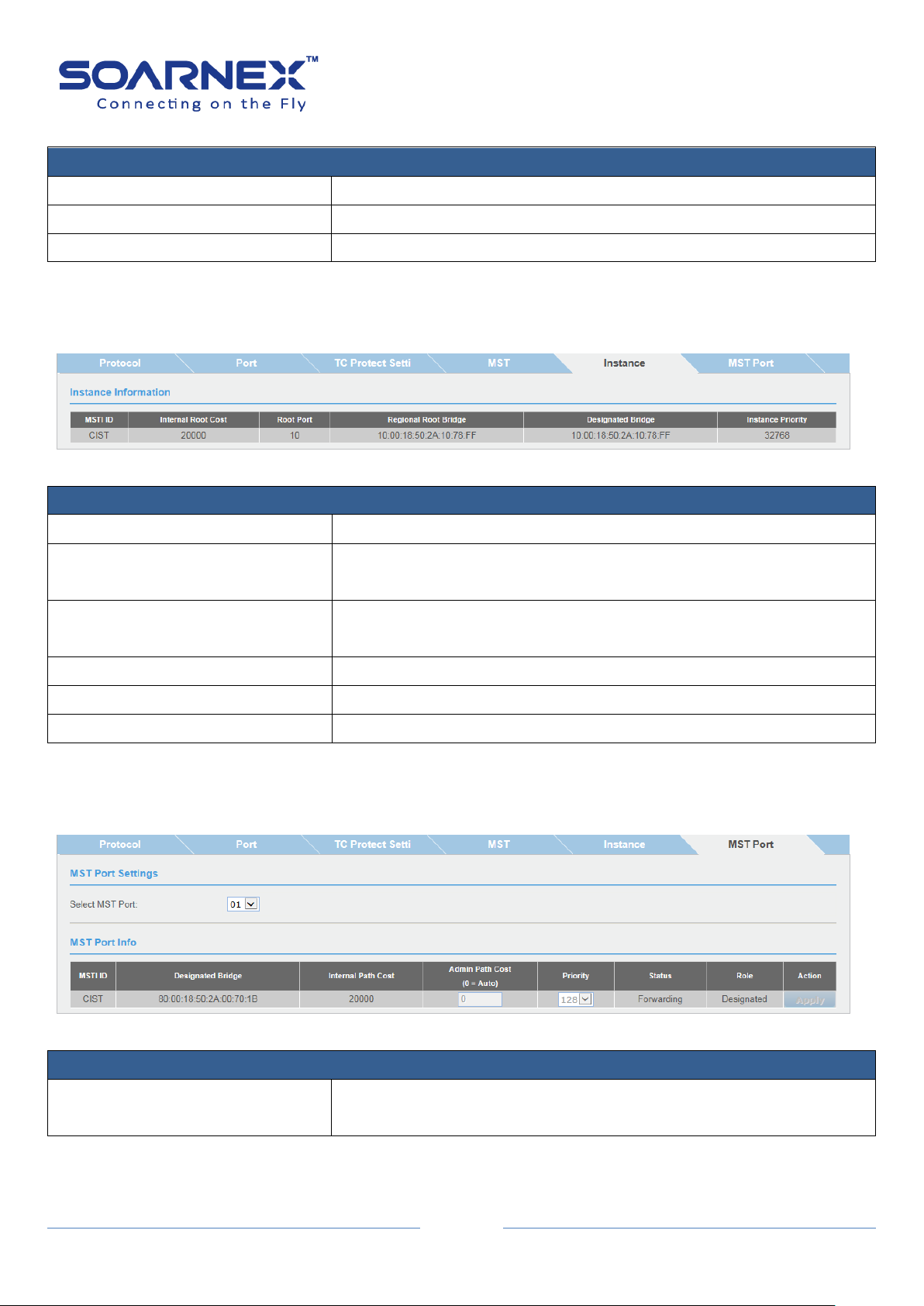
EG210 Series L2+ Smart Managed Switch
70
MST Table
MSTI ID
Displays the MSTI ID associated with the VLAN ID.
VID List
Displays the VLAN ID associated with MSTI.
Priority
Displays the Bridge Priority.
Instance Information
MSTI ID
Specifies the ID of MSTI.
Internal Root Cost
Root cost to the root bridge Root Port: Root port of the specific
instance.
Root Port
The bridge connected with root port.
Designated Bridge: The bridge has connected with designated port.
Regional Root Bridge
The bridge has connected with root port.
Designated Bridge
The bridge has connected with designated port.
Instance Priority
Priority of the instance.
MST Port Settings
Select MST Port
Use the drop-down menu to select the port which you want to
display.
User Manual
3-2-5. Instance
Figure 5-3-2-5 Spanning Tree - Instance
3-2-6. MST Port
Figure 5-3-2-6 Spanning Tree – MST Port

71
MSTI Port Info
MSTI ID
MSTI identification number.
Designated Bridge
The bridge has connected to the designated ports.
Internal Path Cost
The path cost to the designated bridge.
Admin Path Cost (0 = Auto)
This is the port cost used by MSTP when calculating path cost to the
root bridge.
Priority
This is the port priority used by MSTP in calculating path costs when
two ports on the switch have the same port cost.
State
STP port forwarding stat.
Role
The port role in the STP: root port, designated port, backup port, or
disabled port.
3-3. Trunk
EG210 Series L2+ Smart Managed Switch
User Manual
The Trunk is used to create port trunking groups on the Switch; and user can aggregate two
or more links to a single combined link with larger total bandwidth.
There are up to 8 trunk groups can be created (EG210-20-185W, EG210-28-185W,
EG210-28-370W, EG210-52-370W, EG210-52-740W, EG210-28-4C and EG210-52-4C). There
are up to 4 trunk groups can be created (EG210-10-75W, EG210-10-123W and EG210-10-2F).
Each static trunk (manual mode) group can aggregate from 2 to 8 ports, and LACP dynamic
negotiation (Active, Passive mode) group can aggregate from 2 to 10 ports.
Select a trunking group and tick the ports which need to be combined together, and then
click Apply to set Active, Passive or Manual mode for the selected group.
Note: Before user has configured the trunk ports, please do not connect the cables to the
trunk ports till he has configured the ports on both switch and the end nodes.

72
3-3-1. Settings
Trunking Settings
For each Trunk ID (Group), user can select the port numbers and add them into each trunk group.
Active:
Active LACP ports are capable of processing and sending LACP control frames.
Passive:
Passive LACP ports are designated to be passive and cannot initially send LACP control frames.
The LACP dynamic negotiation (Active, Passive mode) group can select 2 to 10 ports in the same Trunk ID.
Manual:
The static trunk (manual mode) group can select 2 to 8 ports in the same Trunk ID.
Disable:
User can select Disable and then clicks Apply to clear all selected ports for a Trunk ID.
EG210 Series L2+ Smart Managed Switch
User Manual
Figure 5-3-3-1 Trunk – Settings

73
3-3-2. Status
LACP Group Status
System Priority
Its pre-assigned setting to the Switch.
This value cannot be modified (gray out).
System ID
The MAC address value is assigned to the Switch.
This value cannot be modified (gray out).
Group ID
The trunk group ID (1~8).
Aggregator: One Group ID has only one aggregator.
Active Port List: Both devices must support LACP and configured
LACP dynamic negotiation (Active, Passive mode) group, those
connected ports are Active ports.
Standby Port List: The LACP dynamic negotiation (Active, Passive
mode) group can select 2 to 10 ports in the same Trunk ID. When
LACP is configured on the Switch, user can try to configure the
maximum number of compatible ports in a trunk group -. The
maximum number is 10 ports.
To set LACP dynamic negotiation Active mode with ports 1~10 in the
same group ID, the port 1~8 are active ports and the port 9~10 in hot
standby state, the standby ports will change to active ports if ports
1~8 has port fail.
EG210 Series L2+ Smart Managed Switch
User Manual
Figure 5-3-3-2 Trunk – Status

EG210 Series L2+ Smart Managed Switch
74
This group isn't LACP mode: If those ports are set to static trunk
(manual mode) group and connected, that is display “This group isn't
LACP mode”
Port Priority Status
System Priority
Display LACP System Priority (32768).
System ID
Display The MAC address value assigned to this switch.
Port Priority Settings
Port
List of port number.
Priority (0-65535)
The port priority determines which ports should be put in standby
mode But there is still a hardware limitation, caused the Switch only
allows maximum 8 ports to be “Active” status at a specified trunk
group. To assign a port with higher priority in a trunk group, users can
find the port number in the priority column, and then enter a priority
value. Its range is from 0 to 65535 (65535 represents the lowest
priority).
3-3-3. Port Priority
The Switch allows user to configure LACP port priority.
User Manual
Figure 5-3-3-3 Trunk – Port Priority
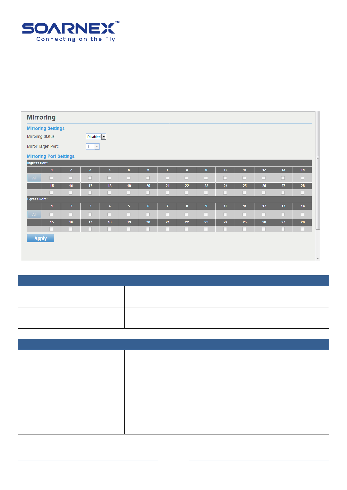
75
3-4. Mirroring
Mirroring Settings
Status
Click the drop-down menu to Enable or Disable Port Mirroring
feature.
Mirror Target Port
Click the drop-down list to select the ports which can receive the copy
of ingress/egress packets from Mirroring Port(s).
Mirroring Port Settings
Ingress Port
Select a specified port number(s) under the Ingress Port section, and
to copy the packets received from specified port(s) to Mirror Target
Port.
User also could click ALL to select all ports as Ingress port.
Egress Port
Select a specified port number(s) under the Egress Port section, and
to copy the packets transmitted from specified port(s) to Mirror
Target Port.
User also could click ALL to select all ports as Egress port.
Port Mirroring allows user to monitor network traffic that forwards copy of each Ingress
(incoming) and/or Egress (outgoing) packets from Mirroring Port(s) to Target Port. A
computer or device can capture the packets for monitoring and troubleshooting purpose.
EG210 Series L2+ Smart Managed Switch
User Manual
Figure 5-3-4 Mirroring

EG210 Series L2+ Smart Managed Switch
76
Loopback Detection Settings
State
Use the drop-down menu to Enable or Disable loopback detection.
The default is Disabled
Select Enabled to enable the loopback detection feature.
Select Disabled to disabled the loopback detection feature.
Interval
Defines the interval (in seconds) that Switch would check for any
loops occurred.
Its range is from 1 to 32767.
Recover Time
Time allows (in seconds) for recovery when a Loopback is detected.
The Loopback detection Recover Time can be set at 0 second, or 60 to
1000000 seconds, entering 0 means NO recovering.
The default is 60 seconds
Its range is 0 or is from 60 to1000000, 0 is Disabled.
3-5. Loopback Detection
The Loopback Detection function is used to detect the loop created by a specified port,
When the Switch detects a loop from a port, the Switch will automatically block the port.
And the Loopback detection port will restart (change to discarding state) when the Loopback
Detection has recovered from the “Recover Time".
Note, Cannot enable Loopback Detection when Spanning Tree is enabled.
User Manual
Figure 5-3-5 Loopback Detection

EG210 Series L2+ Smart Managed Switch
77
Loopback Detection Table
Loopback Detection State
Disable the Loopback Detection State:
Ignore:
This parameter indicates that the setting in the All row do not apply
to the Loopback Detection State field.
Enabled:
This selection enables the Loopback Detection feature for each port.
Disabled:
This selection disables the Loopback Detection feature on the
selected port.
Loop Status
Display the current loopback status.
Normal: The port works normally (none loop).
Loop: The port detects the loop.
Static Unicast Address Settings
802.1Q VLAN
Enter the VLAN ID (1-4094) to create Static Unicast MAC Address
entry. VLAN ID should be existed in 802.1Q VLAN.
Note:
The 802.1Q VLAN filed only can be modified when the Forwarding
Table Mode Settings - learning mode - is IVL.
MAC Address
Enter the MAC Address.
Port Member Settings
User can select a port with MAC Address and VLAN ID to create a Static Unicast forward table.
User Manual
3-6. Static Unicast
User can set up Static Unicast forwarding table on the Switch.
Figure 5-3-6 Static Unicast

78
Static Unicast Table (Free entries: 256)
VLAN Index
Display created VLAN ID entry.
Note:
If 802.1Q VLAN Forwarding Table Mode – learning mode- is SVL the
VLAN Index display is N/A (Not Available).
MAC Address
Display created MAC Address entry
Action
Modify:
User can click the Modify button to change the port mapping
information on the created Static Unicast forward entry.
Delete:
Delete the created Static Unicast forward entry.
Static Unicast Address Settings
802.1Q VLAN
Enter the VLAN ID (1-4094) to create Static Multicast MAC Address
entry, VLAN ID should be existed in 802.1Q VLAN.
Note:
The 802.1Q VLAN filed only can be modified when the Forwarding
Table Mode Settings - learning mode - is IVL.
Group MAC Address
Enter the Multicast MAC Address.
Group Member
User can select more than one port (also can click ALL button to select all ports) with Multicast MAC
Address in the same VLAN ID to create a Static Multicast forward table.
3-7. Static Multicast
EG210 Series L2+ Smart Managed Switch
User Manual
User can set up Static Multicast forwarding table on the Switch.
Figure 5-3-7 Static Multicast

EG210 Series L2+ Smart Managed Switch
79
Static Multicast Table (Free entries: 256)
VLAN Index
Display created VLAN ID entry.
Note,
If 802.1Q VLAN Forwarding Table Mode – learning mode- is SVL, the
VLAN Index display is N/A (Not Available).
MAC Address
Display created Multicast MAC Address entry
Group Members
Display members list on each Group port.
Action
Modify:
User can click the Modify button to change the port mapping
information on the created Static Multicast forward entry.
Delete:
Delete the created Static Multicast forward entry.
User Manual
3-8. IGMP Snooping
The IGMP Snooping enables the Switch to create lists of nodes which belong to the multicast
group’s members.
3-8-1. Settings
If there is no multicast router in the VLAN to initiate the queries, the Administrator
should enable IGMP snooping Querier to send membership query packets. When
the IGMP snooping Querier is enabled, the Switch transmits periodic IGMP query
packets to attached interfaces that trigger IGMP report messages from hosts. The
Switch listens to these IGMP reports to lists of nodes which belong to the multicast
group’s members.

EG210 Series L2+ Smart Managed Switch
80
IGMP Snooping Settings
IGMP Snooping Status
Click drop-down list to Enable or Disable the IGMP snooping feature.
The Default is disabled.
Aging Timeout
The maximum amount of time in seconds to wait a host transmit a
host membership report packets,
After the Switch transmit an IGMP query packets to a host, the Switch
wait the maximum amount of time in seconds for the host transmit a
host membership report packet. Before the time expires the Switch
reminds this host in a multicast group.
Its range is from 130 to 153025 seconds, the default is 260 seconds.
Note, when Querier state enable, the Aging Timeout is calculated as
below formula: (Aging Timeout= Robustness Variable * Query
Interval + Max Response Time). When Query state disable, Aging
Timeout is getting from users' setting."
Querier State
Click drop-down list to Enable or Disable the Switch transmitting
IGMP Query packets. The Default is Disabled.
Fast Leave Status
This feature is used when the Switch receives an IGMP Leave report
without sending an IGMP query message. This feature is can be used
for IGMPv2 hosts. The Default is Disabled.
Figure 5-3-8-1 IGMP Snooping – Settings
User Manual

EG210 Series L2+ Smart Managed Switch
81
Query Interval
The Query Interval is the interval between General IGMP Query
packets. Its range is from 60 to 600 seconds, the default value is 125
seconds.
Note, Host Timeout= Robustness Variable * Query Interval + Max
Response Time
Max Response Time
The amount of time in seconds to allowed before sending an IGMP
response report. Adjusting this value effect the “leave latency” (the
moment of last host leaves a group and when the routing protocol is
notified that there are no more members).
Its range is from 10 to 25 seconds, the default value is 10 seconds.
Robustness Variable
The Robustness Variable value wills changes certain IGMP message
intervals; the Administrator should increase this value if the VLAN is
expected to have packet loss.
Its range is from 2 to 255, the default value is 2.
Note, Host Timeout= Robustness Variable * Query Interval + Max
Response Time
Last Member Query Interval
The amount of time between group-specific query packets. The Last
Member Query Interval is to verify that no IGMP clients want to
receive a particular multicast group on the VLAN. If no IGMP clients
reply IGMP join packets before the last member query interval
expires, the Switch removes the multicast group from the associated
VLAN.
Its range is from 1 to 25 seconds, the default is 1 second.
Router Timeout
The maximum amount of time in seconds to wait a learned router
port received an IGMP query packet. If no IGMP query packet is
receives from the router port before the timeout value, the learned
router port entry will be cancel.
Its range is from 120 to 1200 seconds, the default is 250 seconds.
Multicast Group Entry
VLAN ID
Display this VLAN ID information.
Multicast MAC address
Display the Multicast Group MAC address.
Member Ports
Display the Switch port(s) was learned to a multicast group member.
User Manual
Click Previous Page to return the IGMP Snooping Global Settings page.
Click Apply to apply for the changes.
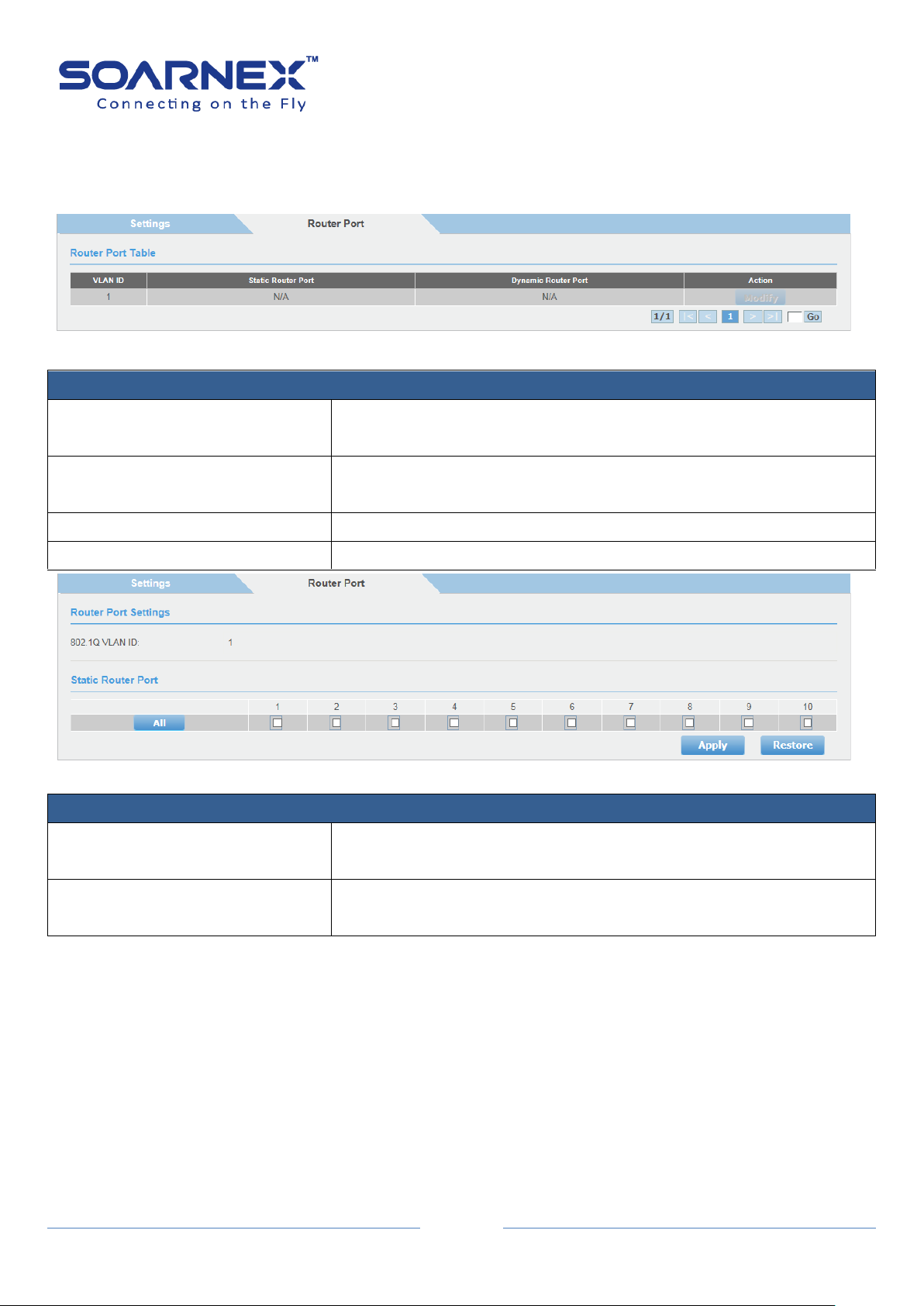
EG210 Series L2+ Smart Managed Switch
82
Router Port Settings
VLAN ID
Display this VLAN ID information, that is identifies the VLAN of the
user wishes to modify the Router Ports Settings
Static Router Ports
Click this option to set the port as being connected to a multicast
enabled router.
Dynamic Router Ports
Display learned Dynamic Router Port for each VLAN.
Action
To modify the router port setting
Router Port Settings
VLAN ID
Display this VLAN ID information, that is identifies the VLAN of the
user wishes to modify the Router Ports Settings
Static Router Ports
Click this option to set the port as being connected to a multicast
enabled router.
3-8-2. Router Ports
Figure 5-3-8-2-1 IGMP Snooping – Router Ports
User Manual
Figure 5-3-8-2-2 IGMP Snooping – Modify IGS Static Router Port
Click All to select all ports. Click Restore to reset all previous selected.
Click Apply to apply for the changes.
3-9. MLD
The MLD Snooping enables the Switch to create lists of nodes which belong to the IPv6
multicast group's members.

83
3-9-1. Settings
MLD Snooping Settings
MLD Snooping Status
Click drop-down list to Enable or Disable the MLD snooping feature.
The Default is disabled.
If there is no multicast router in the VLAN to initiate the queries, the Administrator
should enable MLD snooping Querier to send membership query packets. When
the MLD snooping Querier is enabled, the Switch transmits periodic MLD query
packets to attached interfaces that trigger MLD report messages from hosts. The
Switch listens to these MLD reports to lists of nodes which belong to the multicast
group’s members.
EG210 Series L2+ Smart Managed Switch
User Manual
Figure 5-3-9-1 MLD – Settings

EG210 Series L2+ Smart Managed Switch
84
Aging Timeout
The maximum amount of time in seconds to wait a host transmit a
host membership report packets,
After the Switch transmit an MLD query packets to a host, the Switch
wait the maximum amount of time in seconds for the host transmit a
host membership report packet. Before the time expires the Switch
reminds this host in a multicast group.
Its range is from 130 to 153025 seconds, the default is 260 seconds.
Note, when Querier state enable, the Aging Timeout is calculated as
below formula: (Aging Timeout= Robustness Variable * Query
Interval + Max Response Time). When Query state disable, Aging
Timeout is getting from users' setting."
Querier State
Click drop-down list to Enable or Disable the Switch transmitting MLD
Query packets. The Default is Disabled.
Fast Leave Status
This feature is used when the Switch receives an MLD Leave report
without sending an MLD query message. This feature is can be used
for MLD hosts. The Default is Disabled.
Query Interval
The Query Interval is the interval between General MLD Query
packets. Its range is from 60 to 600 seconds, the default value is 125
seconds.
Note, Host Timeout= Robustness Variable * Query Interval + Max
Response Time
Max Response Time
The amount of time in seconds to allowed before sending an MLD
response report. Adjusting this value effect the “leave latency” (the
moment of last host leaves a group and when the routing protocol is
notified that there are no more members).
Its range is from 10 to 25 seconds, the default value is 10 seconds.
Robustness Variable
The Robustness Variable value wills changes certain MLD message
intervals; the Administrator should increase this value if the VLAN is
expected to have packet loss.
Its range is from 2 to 255, the default value is 2.
Note, Host Timeout= Robustness Variable * Query Interval + Max
Response Time
User Manual
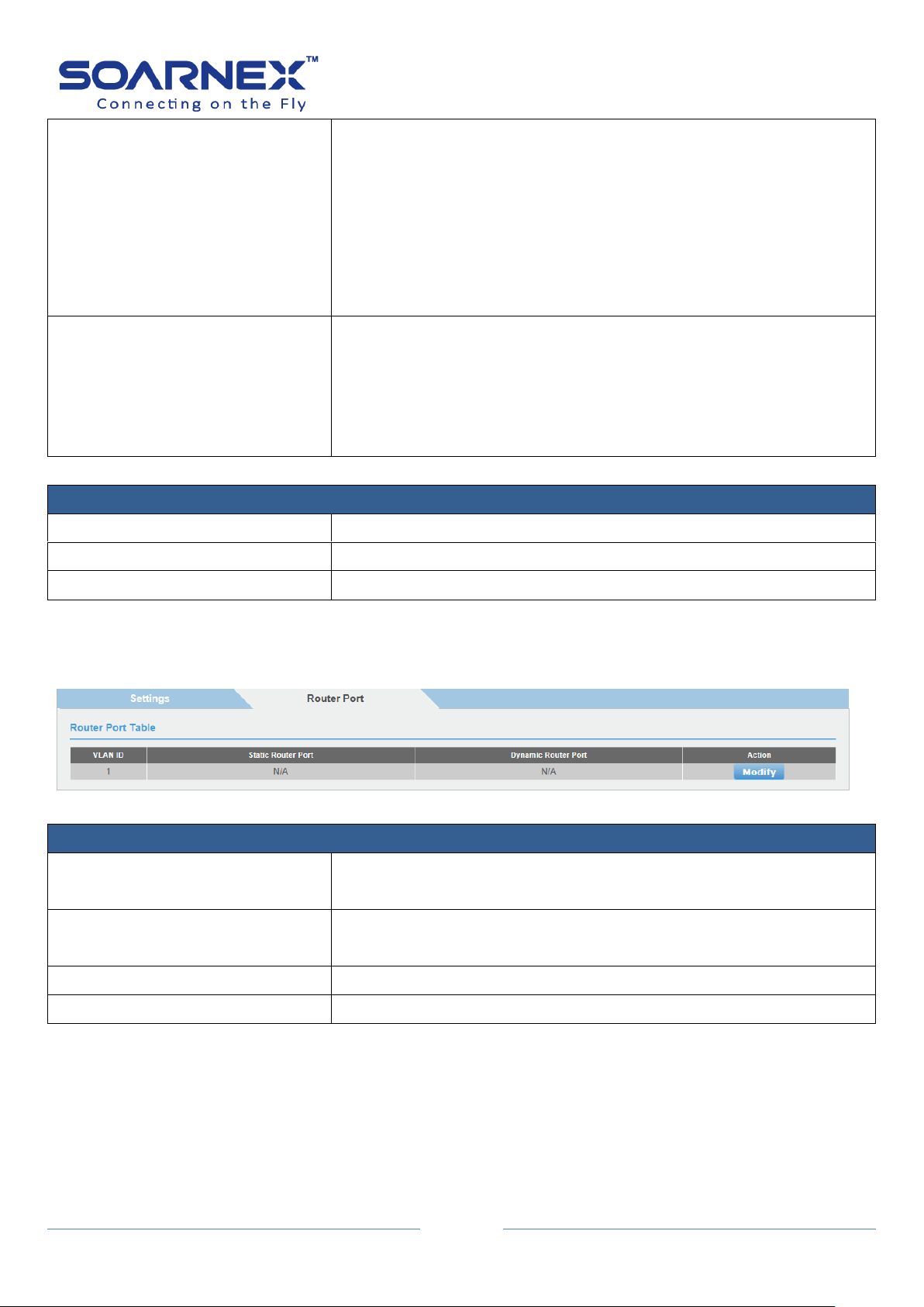
EG210 Series L2+ Smart Managed Switch
85
Last Member Query Interval
The amount of time between group-specific query packets. The Last
Member Query Interval is to verify that no MLD clients want to
receive a particular multicast group on the VLAN. If no MLD clients
replies MLD join packets before the last member query interval
expires, the Switch removes the multicast group from the associated
VLAN.
Its range is from 1 to 25 seconds, the default is 1 second.
Router Timeout
The maximum amount of time in seconds to wait a learned router
port received an MLD query packet. If no MLD query packet is
receives from the router port before the timeout value, the learned
router port entry will be cancel.
Its range is from 120 to 1200 seconds, the default is 250 seconds.
Multicast Group Entry
VLAN ID
Display this VLAN ID information.
Multicast MAC address
Display the Multicast Group MAC address.
Member Ports
Display the Switch port(s) was learned to a multicast group member.
Router Port Settings
VLAN ID
Display this VLAN ID information, that is identifies the VLAN of the
user wishes to modify the Router Ports Settings
Static Router Ports
Click this option to set the port as being connected to a multicast
enabled router.
Dynamic Router Ports
Display learned Dynamic Router Port for each VLAN.
Action
To modify the router port setting
User Manual
Click Previous Page to return the MLD Snooping Global Settings page. Click Apply to apply for the changes.
3-9-2. Router Port
Figure 5-3-9-2-1 MLD Snooping – Router Ports

EG210 Series L2+ Smart Managed Switch
86
Router Port Settings
VLAN ID
Display this VLAN ID information, that is identifies the VLAN of the
user wishes to modify the Router Ports Settings
Static Router Ports
Click this option to set the port as being connected to a multicast
enabled router.
Figure 5-3-9-2-2 IGMP Snooping – Modify IGS Static Router Port
Click All to select all ports. Click Restore to reset all previous selected.
Click Apply to apply for the changes.
User Manual
3-10. Multicast VLAN
The multicast VLAN to create shared VLANs used for multicasting. The multicast VLAN allow different VLAN
port member using the multicast VLAN for multicast streams. The multicast client may join and leave the
multicast group.
3-10-1. Multicast VLAN Settings
Figure 5-3-10-1-1 Multicast VLAN Settings

EG210 Series L2+ Smart Managed Switch
87
Multicast Global Settings
Multicast IPv4 state
Click pull-down list to Enable or Disable multicast IPv4 state.
By default, the multicast IPv4 state is disabled.
Multicast IPv6 state
Click pull-down list to Enable or Disable multicast IPv6 state.
By default, the multicast IPv6 state is disabled.
Apply
To click Apply button to Enable or Disable multicast VLAN state.
Multicast VLAN Settings
VLAN ID
Enter the VLAN ID (2-4094) to create multicast VLAN interface.
VLAN Name
Enter the VLAN name (32 characters limit).
Add and Delete button
After enter the VLAN ID then click Add button to create the multicast
VLAN interface.
After enter the VLAN ID then click Delete button to delete the
multicast VLAN interface.
Multicast VLAN interface max entry is 5.
The Port Setting of Multicast
VLAN ID
Display the multicast VLAN ID number.
VLAN Name
Display the multicast VLAN name.
State
User also can manual Enable or Disable the created multicast VLAN
state by the pull-down list and click Apply button.
Receiver Ports
Click the Edit button to setup the receive port for receive multicast
stream, the receive port is connected to the multicast client.
Select the multicast
receiver ports
(untagged or tagged
port) then click Apply
button. User can
delete all receiver
ports settings by click
Clear button.
Click Previous page button to back "Multicast VLAN Settings" page.
Note, A receiver port can belong to multiple multicast VLANs.
User Manual
Figure 5-3-10-1-2 the Port Setting of Multicast
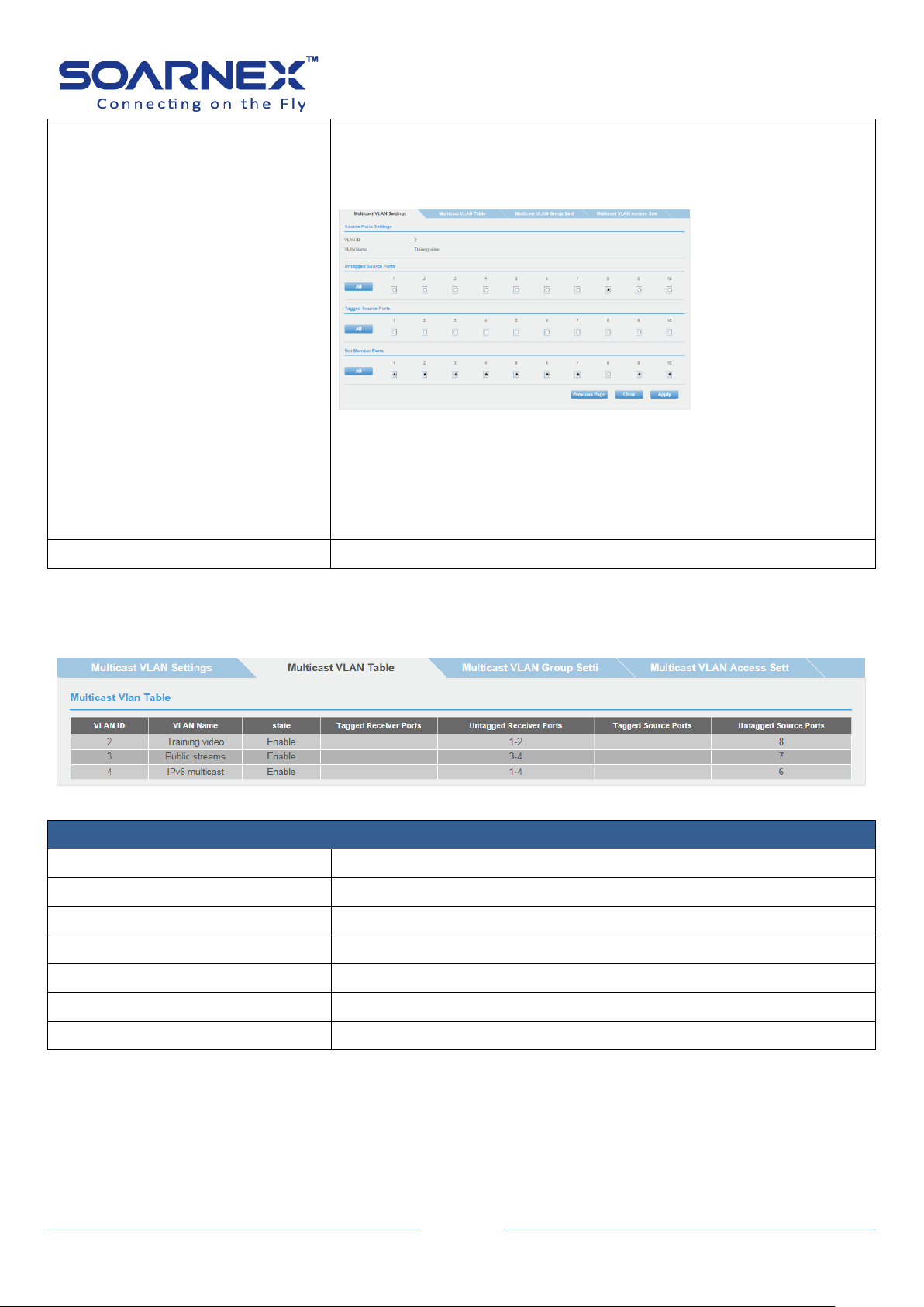
EG210 Series L2+ Smart Managed Switch
88
Source Ports
Click the Edit button to setup the source port for transmit/receive
multicast traffic, the source port is connected to multicast server or
multicast router device.
Select the multicast
source ports
(untagged or tagged
port) then click Apply
button. User can
delete all receiver
ports settings by click
Clear button.
Click Previous page button to back "Multicast VLAN Settings" page.
The source ports in a single Multicast VLAN must all be either tagged
members or untagged members.
Note, the same source port cannot set to in different multicast VLAN.
Action
Click Apply button to accept this multicast VLAN settings.
Multicast VLAN Table
VLAN ID
Display the multicast VLAN ID.
VLAN Name
Display the multicast VLAN name.
State
Display the multicast VLAN state.
Tagged Receiver Ports
Display the multicast tagged receiver ports number.
Untagged Receiver Ports
Display the multicast untagged receiver ports number.
Tagged Source Ports
Display the multicast tagged source ports number.
Untagged Source Ports
Display the multicast untagged source ports number.
User Manual
3-10-2. Multicast VLAN Table
Figure 5-3-10-2 Multicast VLAN Table

EG210 Series L2+ Smart Managed Switch
89
Profile Create
Profile Create
Enter the multicast VLAN profile name (32 characters limit).
Group Profile Settings
Profile Name
Enter the multicast VLAN profile name that you crated before.
IP Address Range
Choice “IPv4” to setup IPv4 multicast address range for this multicast
VLAN profile. Or choice “IPv6” to setup IPv6 multicast address range
for this multicast VLAN profile.
The profile entry must less than 80.
Multicast Profile Table
Profile Name
Display the multicast profile name.
Multicast Profile Groups
Display the multicast profile group addresses.
Action
User can click Delete button to remove created multicast VLAN
profile entry.
3-10-3. Multicast VLAN Group Settings
User Manual
Figure 5-3-10-3 Multicast VLAN Group Settings

EG210 Series L2+ Smart Managed Switch
90
Associate Group Settings
VLAN ID
Enter the multicast VLAN ID (number) that you created before.
For Assign the multicast profile name (with its multicast groups) to
dedicated multicast VLAN ID.
Profile Name
Enter the multicast VLAN profile name that you create before.
For Assign the multicast profile name (with its multicast groups) to
dedicated multicast VLAN ID.
Multicast Associate Group Table
Multicast VLAN ID
Display the multicast VLAN ID.
Multicast Profiles Name
Display the multicast VLAN profile name.
3-10-4. Multicast VLAN Access Settings
Figure 5-3-10-4 Multicast VLAN Access Settings
User Manual
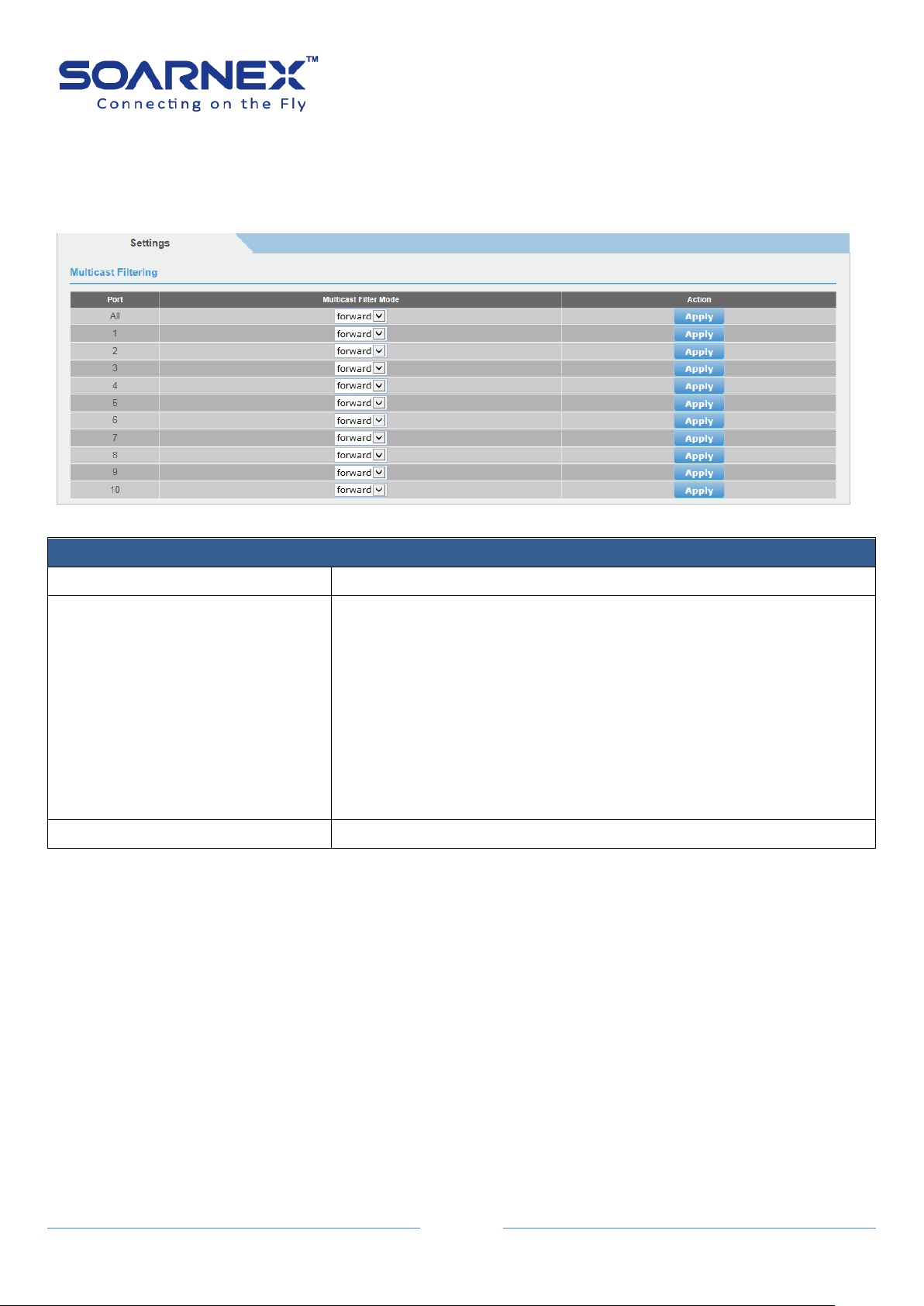
EG210 Series L2+ Smart Managed Switch
91
Multicast Settings
Port
Display the port number.
Multicast Filter Mode
Click drop-down list to select the Multicast Filter Mode.
There are two types of Multicast Filter Mode:
Forward:
When filter mode is Forward, all multicast groups including
unregistered and registered will be forwarded.
Filter:
When filter mode is Filter, all unregistered multicast groups will be
dropped and not forward anymore.
Action
Click Apply button to accept this port multicast filtering settings.
3-11. Multicast Filter
3-11. The Switch forwards Multicast packets to all ports by default.
Figure 5-3-11 Multicast Filtering Settings
User Manual

EG210 Series L2+ Smart Managed Switch
92
Storm Control Settings
Port
The port number user wants to implement the storm control on a
port.
DLF
Click the drop-down list to Enable or Disable DLF (Destination Lookup
Failure) storm control. Note: When the Switch receives a packet, it
will scan the forwarding database and look for a match to the
destination MAC address from the received packet, if the received
packet (Destination Unicast MAC Address) cannot been found in the
forwarding database, that also means Destination Lookup Failure.
Broadcast
Click the drop-down list to Enable or Disable Broadcast storm control
on a port.
Multicast
Click the drop-down list to Enable or Disable Multicast storm control
on a port.
Threshold
Enter the pps (packets per second) threshold to limit the amount of
DLF, Broadcast and Multicast packets accepted and forwarded by the
device on a port. Its range is from 1 to 4096.
Action
Click Apply to apply the changes on a port.
3-12. Bandwidth Control
3-12-1. Storm Control
The Switch provides the ability to control received rate of DLF (Destination Lookup
Failure), Broadcast and Multicast packets. When a packet storm type has been
detected over the threshold that user has configured, the Switch will drop packets
till the storm has been suppress.
User Manual
Figure 5-3-12-1 Bandwidth Control – Storm Control

EG210 Series L2+ Smart Managed Switch
93
Ingress Rate Limiting Settings
Port
The port number that user wants to implement the Ingress Rate
Limiting on a port.
Bandwidth
Enter the ingress rate limit value on a port.
Note: the GE ports have a maximum speed of 1000000 kilobits per
second (64kbps x 15625 = 1000000 kilobits)
Status
Click the drop-down list to Enable or Disable ingress rate limiting on a
port.
Action
Click Apply to apply the changes on a port.
3-12-2. Ingress Rate Limiting
Figure 5-3-12-2 Bandwidth Control – Ingress Rate Limiting
User Manual
3-12-3. Egress Rate Limiting
Figure 5-3-12-3 Bandwidth Control – Egress Rate Limiting

94
Egress Rate Limiting Settings
Port
The port number that user wants to implement the Egress Rate
Limiting on a port.
Bandwidth
Enter the Egress rate limit value on a port.
Note: the GE ports have a maximum speed of 1000000 kilobits per
second (64kbps x 15625 = 1000000 kilobits)
Status
Click the drop-down list to Enable or Disable Egress rate limiting on a
port.
Action
Click Apply to apply the changes on a port.
3-13. VLAN
A Virtual Local Area Network (VLAN) is a network topology configured according to a logical
scheme rather than the physical layout.
VLAN also logically segment the network into different broadcast domains so that packets
EG210 Series L2+ Smart Managed Switch
User Manual
are forwarded only between ports within the VLAN.
VLAN can enhance performance by conserving bandwidth, and improve security by limiting
traffic to specific domains.
A VLAN is a collection of end nodes grouped by logic instead of physical location. End nodes
that frequently communicate with each other are assigned to the same VLAN, regardless of
where they are physically on the network. Logically, a VLAN can be equated to a broadcast
domain, because broadcast packets are forwarded to only members of the VLAN on which
the broadcast was initiated. User can be easily organized to reflect department groups (such
as R&D, Marketing), usage groups (such as e-mail), or multicast groups (multimedia
applications such as video conferencing), and therefore help to simplify network
management by allowing users to move devices to a new VLAN without having to change
any physical connections.
The Switch’s default is to assign all ports to a single 802.1Q VLAN named “default.”, the
“default” VLAN has a VID = 1 as untagged ports.

EG210 Series L2+ Smart Managed Switch
95
Tagged VLAN Settings
VLAN ID
The VLAN ID is the VLAN identifier and is used by the 802.1Q
standard. The VID is 12 bits long, 4094 unique VLANs can be
identified. The Switch default VLAN ID is 1, you can set VID range is 2
to 4094.
VLAN Name
Enter the VLAN name (32 characters limit)
3-13-1. Tagged
You can add ports to the new VLAN (Tagged or Untagged) and assign ports
that are Not Members (Forbidden) of the new VLAN.
User Manual
Figure 5-3-13-1 VLAN – Tagged
Every port on an 802.1Q compliant switch can be configured as tagging or untagged.
EG210 Series L2+ Smart Managed Switch
96
Static Tagged
Tagged VLAN ports can be included as members for multiple VLANs. Computers and other edge devices are
not typically connecting to tagged VLAN ports unless the network interface on these devices can be
enabled to be VLAN aware.
Static Untagged
Untagged VLAN ports are used to connect edge devices (VLAN unaware) such as computers, laptops, and
printers to a specified VLAN.
It is required to modify the Port VID settings accordingly for untagged VLAN ports under Bridge > VLAN >
Port Settings. (e.g. If the VID for the VLAN is 2, the PVID should also be set to 2)
Not Member
Allow an individual port to be specified as a non-VLAN member
Tagged VLAN Table
VLAN ID
Display current VLAN ID table.
Name
Display current VLAN Name for each VLAN.
VLAN Type
Display current VLAN Type for each VLAN.
The default VLAN is Permanent.
The manual created VLAN is Static.
VLAN Action
Modify:
Click Modify to modify a VLAN, and user can modify VLAN Name and
changes each port as Tagged, Untagged or Not Member.
Delete:
Click Delete to delete the VLAN.
User Manual
Note, If the transmitting port is connected to a tag-unaware device, the packet should be untagged.
If the transmitting port is connected to a tag-aware device, the packet should be tagged.
Modify button:
If user clicks Modify button in Tagged VLAN table then he can modify VLAN name, Static Tagged, Static
Untagged or Not member port.
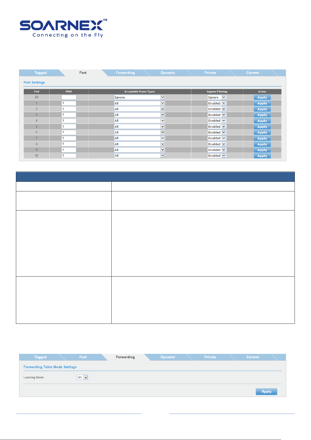
97
3-13-2. Port
Port Settings
Port
Display the port number.
PVID
Enter the port VLAN ID
Note: Require for untagged VLAN ports.
Acceptable Frame Type
Use the drop-down list to select which type of frames can be
accepted.
All: The port can accept all frame type.
Tagged: The port can accept tagged frames only, which are means
untagged frames are discarded.
Untagged with Priority Tagged: The port can accept untagged frames
and frames with tagged priority information only such as 802.1p.
Ingress Filter
Use the drop-down list and select Enabled to enable ingress filtering
or Disabled to disable ingress filtering.
Note:
To enable Auto Detection function in Voice VLAN, the ingress filtering
of VLAN should be disabled.
Figure 5-3-13-2 VLAN – Port
EG210 Series L2+ Smart Managed Switch
User Manual
3-13-3. Forwarding
Figure 5-3-13-3 VLAN – Forwarding

EG210 Series L2+ Smart Managed Switch
98
Forwarding Table Mode
Learning Mode
Use the drop-down list and select VLAN learning mode: IVL or SVL
Independent VLAN Learning, IVL: Each VLANs have its own logical
source address table.
Shared VLAN Learning, SVL (or Asymmetric VLAN mode): There are
two or more VLANs share common source address information. This
is useful for configuration of more complex traffic (Asymmetrical
VLAN).
It is recommended to use the standard 802.1Q VLAN mode (IVL) when possible.
Please note the following when switching Learning Mode between forwarding table modes:
FDB (Forwarding Database) will be cleared.
Static Unicast Address entries will be cleared.
Static Multicast Address entries will be cleared.
802.1X authenticated records will be cleared.
IGMP Snooping multicast group addresses will be cleared
User Manual
When using SVL mode, Voice VLAN will not be supported.
When using SVL mode, the VID field on 802.1Q-VLAN mode will be
displayed as "N/A".
User can find the change in Bridge -> VLAN -> Dynamic Forwarding
Table page.
3-13-4. Dynamic
Figure 5-3-13-4 VLAN – Dynamic

EG210 Series L2+ Smart Managed Switch
99
Dynamic Forwarding Table Settings
Port
User can select the port number for display this port’s dynamic
forwarding table.
Default is display All ports dynamic forwarding table.
Dynamic Forwarding Table
ID
Display the forwarding table ID.
VID
Display the VID of the port when the Forwarding Table Mode is IVL.
If the Forwarding Table Mode is SVL, this field display N/A.
Port
Display the port number.
MAC Address
Display the MAC Address.
Type
Display the forwarding table learned type.
3-13-5. Private
User Manual
The Private VLAN is used to limit traffic flow from a single port (source port)
to a group of ports (forwarding port).
Figure 5-3-13-5 VLAN – Private
 Loading...