


MY2004
Set-up, Service
and Shop Manual
SNOW HAWK 600HO
FOREWORD
Congratulations, and thank you for buying an A.D.
Boivin design inc. Snow Hawk™ vehicle. We
appreciate the confidence in our product that you
have demonstrated by making this purchase
Several years of design, tests and improvements
were necessary to produce this vehicle which
combines performance, driving pleasure and safety.
Proper maintenance on a regularly-scheduled basis is
essential in order to obtain the performance you have
the right to expect from your machine. In this manual,
you will find all the information needed for adjustments
to and the maintenance of this vehicle.
We sincerely hope that you will have many years of
enjoyment with your Snow Hawk™.
.
AD Boivin design Inc.
All the information, illustrations, photographs and
specifications found in this manual are based on the
latest available data at the time of publication. Due to
improvements or other changes, it is possible that
you will note a few differences. AD Boivin design Inc.
reserves the right to make changes at any time.
WARNING /CAUTION / NOTICE
●
NOTICE:
The information in the NOTICES is designed to
explain maintenance procedures and to ensure the
best possible use of the vehicle.
IMPORTANT REMARKS
Using this vehicle can be a very pleasurable
experience and we wish you all the enjoyment that it
can bring you. However, if certain rules are not
respected, this sport can become a source of
environmental problems and of interpersonal
conflicts.
Adopting a responsible attitude and behaving in a
responsible manner at all times will help avoid such
problems and conflicts.
PROTECT THE FUTURE OF YOUR SPORT. BE
RESPONSIBLE AND RESPECT LOCAL LAWS AT
ALL TIMES. DEMONSTRATE AN AWARENESS
OF THE IMPORTANCE OF THE ENVIRONMENT
AND RESPECT THE RIGHTS OF OTHERS.
WARRANTY
1. All the parts of this vehicle are covered by the
warranty for a period of one winter season
against any problem related to its assembly
or construction.
Please read this manual and follow the instructions
carefully. Pay particular attention to the boxes
entitled WARNING and CAUTION as well as to the
paragraphs preceded by the word NOTICE.
◆ WARNING
This symbol is designed to call attention to
particular instructions and procedures, which,
if not followed to the letter, could cause injury
and even fatal accidents.
▼ CAUTION
This symbol is designed to call attention to
particular instructions and procedures, which,
if not followed to the letter, could cause
damage to or even destruction of the vehicle.
2. The labour costs of repairs covered by the
warranty are the responsibility of the vehicle
owner.
3. The company reserves the right to require
that the dealer carrying out the repairs send
back any parts declared or suspected to be
defective.
LOCATION OF THE V.I.N.

IMPORTANT MAINTENANCE WARNINGS:
◆ WARNING
Never have the motor running inside a building.
The exhaust fumes contain carbon monoxide, a
colourless, odourless gas which can cause
death or severe injuries.
Allow the motor to run only in a well-ventilated
area.
◆ WARNING
When hot, a motor, an exhaust system or a
drive system can cause burns.
Wait until they have cooled before carrying out
maintenance.
◆ WARNING
The gas tank can catch fire if it is not handled
correctly. Gas vapours can burst into flames
easily.
◆ WARNING
Carrying out maintenance of this vehicle while
the motor is running can be dangerous.
Injuries could result from contact with moving
parts.
Make sure you turn off the motor before
working on the vehicle.
◆ WARNING
Working on this vehicle without wearing the
appropriate clothing can be dangerous.
Injuries could result if you are not adequately
protected.
Always wear the necessary equipment when
working on the vehicle: shoes, goggles, gloves
and/or mask if necessary.
Important information concerning maintenance
o Replace any joints, brake shoes, pins and clips
by new ones.
Do not smoke while carrying out vehicle
maintenance.
Do not carry out maintenance anywhere near
exposed flames or sparks.
◆ WARNING
Brake fluid can be dangerous for people and
animals. These fluids are harmful or fatal if
swallowed and must not come into contact with
the skin or eyes.
o Use special tools when so indicated.
o Use original parts as well as recommended
products.
o After reassembling the vehicle, inspect the parts
and verify the torque on the nuts and bolts.
Replacement parts
Use only A D Boivin parts or their equivalent. A D
Boivin’s original high-quality parts are designed and
manufactured especially for your vehicle.
●
NOTICE:
Using replacement parts that are not equivalent or
are of inferior quality could mean your vehicle will not
be able to perform as it should and could damage
your machine.
MANDATORY SERVICE PRODUCTS
Loctite RC/609, 10 ml
Retaining compound
P/N 413 703 100
Loctite 271, 10 ml
High strength
threadlocker
P/N 293 800 005
Loctite 243, 10 ml
Medium-strength
threadlocker
P/N 293 800 015
Sealing compound, 30 ml
P/N 420 297 905
Loctite Primer, 128g
P/N 413 708 100
Loctite 515, 50 ml
Paste gasket
P/N 413 702 700
MANDATORY SERVICE PRODUCTS (continued)
Loctite chisel, 510g
Gasket/paint remover
P/N 420 899 763
Molykote G-n plus. 50g
P/N 711 297 433
Molykote PG 54, 10g
P/N 420 899 763
Isoflex Grease, 50g
P/N 293 550 021
Petamo Grease
P/N 420 899 271
Loctite 518, 50 ml
Gasket Paste
P/N 293 800 038

RECOMMENDED SERVICE PRODUCTS
Bombardier injection oil
3 x 4 litres P/N 413 803 000
Pre-mix oil
12 x 500ml P/N 413 803 100
Premixed coolant 50/50
16 x 1 litre P/N 293 600 038
Synthetic injection oil
Bombardier Formula XP-S II
3 x 4 litres P/N 293 600 046
Synthetic injection oil
Bombardier Formula XP-S II
12 x 1 litre P/N 293 600 045
Fuel stabilizer
12 x 8 oz P/N 413 408 600

RECOMMENDED SERVICE PRODUCTS (continued)
Storage oil 12 x 350 g
Canada P/N 413 711 600
USA P/N 413 711 900
Synthetic Grease 400 g
P/N 413 711 500
LMZ Grease No 1, 400 g
P/N 413 707 500
Molykote 111, 50 g
P/N 413 707 000
Bombardier lube
12 x 14 oz P/N 293 600 016
Silicone dielectric grease, 3 oz
P/N 293 550 004

RECOMMENDED SERVICE PRODUCTS (continued)
Anti-seize compound, 236 ml
P/N 293 800 070
Pulley flange cleaner, 320 g
P/N 413 711 809
Brake fluid SRF ( DOT 4 )
P/N 293 600 063
Heavy Duty Cleaner
400 g P/N 293 110 001
4 litres P/N 293 110 002
Brake fluid GTLMA (DOT 4)
P/N 293 600 062
Shock oil 32 oz
P/N 293 600 035

RECOMMENDED SERVICE PRODUCTS (continued)
Loctite 592, 50 ml
Pipe sealant
P/N 293 800 018
Loctite 648, 5 ml
High temperature and strength
retaining compound
P/N 413 711 400
Plastic and vinyl cleaner
P/N 413 711 200
Loctite Ultra Copper, 80 ml
High temperature RTV sealant
P/N 293 800 090
Loctite 5150, 300ml
P/N 293 800 066

TABLE OF CONTENTS
GENERAL INSTRUCTIONS
PERIODIC MAINTENANCE
FUEL SYSTEM
ENGINE REMOVAL
REWIND STARTER
COOLING SYSTEM
ENGINE (CYLINDERS / HEAD / BASE)
PRIMARY TRANSMISSION SYSTEM
SECONDARY TRANSMISSION SYSTEM
1
2
3
4
5
6
7
8
9
HYDRAULIC BRAKE SYSTEM
FRONT FORK AND TWIN-AXIS SKI
REAR SUSPENSION, SHOCKS AND TRACK
CHASSIS AND STEERING
ELECTRICAL SYSTEM
DIMENSIONS AND TOLERANCES
WIRE, CABLE AND HOSE ROUTING
10
11
12
13
14
15
16

FIRST CONTACT
The SNOW HAWK™ is a completely new type of vehicle.
Technically speaking, it is a cross between a snowmobile and a
motorcycle. However, its behaviour depends on the conditions in
which it is used. Sometimes, it will react more like a bike while
at other times, it will react more like a snowmobile or a jetski.
Describing exactly how the SNOW HAWK™ behaves is difficult.
This is why we recommend that you take the time to become
acquainted with your machine in an area free of any obstacle.
This first contact should take place at low speed, with a series of
basic manoeuvres that will allow you to learn about the reactions
of the vehicle.
A good exercise is to follow a "figure 8" trajectory because this
will allow you to experiment with right- and left-hand turns
followed by accelerating and braking.
Turning can be done by steering right or left, keeping in mind the
speed of the vehicle, the snow conditions and how quickly you
want to change direction.
GENERAL INSTRUCTIONS 1 - 1
◆ WARNING
Some people enter a turn by stretching out a leg on the
inside of the turn and letting the foot slide over the
ground (a technique used in motocross). We advise
against this practice which could cause severe injuries if
your foot should sink into the snow. We rather suggest
keeping both feet on the footpegs as much as possible.
An upright position, with the knees clutching the gas tank and
the elbows pointing away from the vehicle, will give a sense of
security and provide greater freedom of movement while
accelerating or slowing down.
◆ WARNING
The greatest danger in using this vehicle is the perception
you may have of how competent you are. Overestimating
how competent you are can result in hazardous situations
both for yourself and for other trail users.
Do not forget to take all the time that is necessary for you to
practice and feel comfortable at low speeds before attempting
high-speed manoeuvres. You will then be able to fully
appreciate the joy of driving.

GENERAL INSTRUCTIONS 1 - 2
LOCATION OF MECHANISMS AND CONTROLS (503 SHOWN, 600HO IDENTICAL)
8
6
1
1. Throttle control
2. Brake lever
4
5
3
2
9
7
3. Parking brake lever
4. Engine-cutoff (tether)
5. Gas tank cap
6. Dimmer switch
7. Choke control
8. Emergency-stop button
9. Temperature Light
14
10
15
10. Hood latches (4)
11. Rear module latches (4)
12. Bellypan latches (6)
11
13. Kick stand
14. Headlight
13
15. Stop and tail light
12
18
16
17
16. Recoil starter handle
17. Hood latches (4)
18. Rear module latches (4)
19. Bellypan latches (6)
19
FUEL
(
)
(
)
0
This vehicle is powered by a two-stroke engine that uses a premixed gasoline and oil mixture.
Gasoline: Regular unleaded gas with a minimum octane
rating of 89 (R+M)/2
GENERAL INSTRUCTIONS 1 - 3
Motor oil: Bombardier / ROTAX Formula XPS Synthetic
Pre-mix oil (P/N 293600045)
Mixture ratio: 40 : 1 (32 : 1 for break in and CAN safely be
used thereafter if desired)
Fuel tank capacity: 30 L (9.5 gallons)
▼ CAUTION
A mixture in which the proportion of oil is too low will
cause piston failure. On the other hand, a mixture in
which the proportion of oil is too high will cause
excessive carbon deposits that will result in fouled spark
plugs and will affect performance.
Always mix in a proportion of 40 parts of gasoline for
each part of oil.
●
NOTICE:
o The use of isop[ropyl alcohol (commonly known as “gas-
line antifreeze) is recommended in a ratio of 150 mL per
fuel tank in very cold temperatures.
Gasoline
L
Oil
ml
5125
10 250
15 375
20 500
25 625
30 75
o Avoid mixing oils of different brands.

GENERAL INSTRUCTIONS 1 - 4
OPERATING INSTRUCTIONS
Pre-driving inspection
◆ WARNING
A pre-driving inspection is of the utmost importance
before using the vehicle. Do not start the machine until
you are sure all mechanisms and controls are functioning
properly. Failing to proceed in the prescribed manner may
result in severe injuries or even death.
o Make sure the track and the idler wheels are not frozen and
that they move freely.
o Depress the brake lever and make sure the brake is fully
engaged before the end of the lever touches the handlebar.
The lever must return to its original position as soon as it is
released.
o Turn the twist throttle control a few times to make sure it
functions properly. The control must return automatically to
the idle position as soon as it is released.
o Make sure the engine cutoff switch, the stop light, the
headlight (high and low beams) and the tail light are in good
working order.
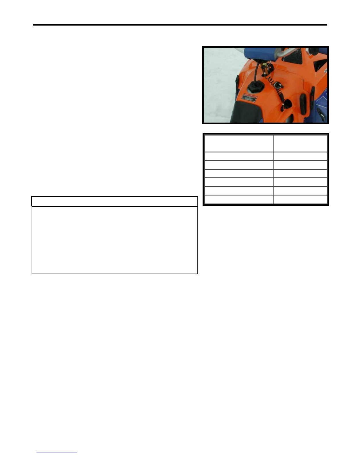
Starting the engine
o Put the cap of the engine cutoff (tether) switch in place. The
other end of the cord must be securely attached to the
driver.
o If the engine is cold, use the choke control.
0. Normal position (not activated)
1. Intermediate choke position
2. Full choke position
o Start the engine by firmly pulling the handle of the rewind
starter.
◆ WARNING
Do not touch the throttle control while starting the engine.

Stopping the engine
o While the engine is idling, remove the engine cutoff cap
(tether) or press the emergency-stop button.
BREAK-IN PERIOD
Engine
▼ CAUTION
A cautious break-in period of 10 to 15 hours is essential
before using the vehicle at full power. Failure to provide a
sufficient break-in period could result in severe engine
damage.
▼ CAUTION
The timing of all Snow Hawk 600HO’s is retarded by 3o for
a period of 1-hour during the first stages of the break-in
period. You may notice a slight increase in performance
and a reduction in fuel consumption after this time.
GENERAL INSTRUCTIONS 1 - 5
During the break-in period, the throttle control should not be
turned more than ¾ of its range. However, occasional periods
of brief, brisk acceleration and frequent speed variations
contribute to a good break-in. On the other hand, periods of
long, high acceleration, sustained high speed and engine
overheating are harmful during the break-in period.
◆ WARNING
This vehicle is equipped with a liquid cooling system.
ALWAYS ride with the rear deflector pad installed and in
conditions where there is enough snow to properly cool
the engine. If the red temperature light on the steering
column should ever illuminate, stop immediately and let
the vehicle cool down, and then find some snow. NEVER
continue to operate the vehicle with the temperature light
illuminated as severe engine damage will occur.
▼ CAUTION
A fuel : oil mixture of 32 : 1 MUST be used during the
engine break-in period.
◆ WARNING
During the first hour of the break-in period the fluid levels
in the coolant reservoir and the small water pump oil
reservoir will go down slightly. This is perfectly normal.
Be sure to top-up these fluids with proper coolant (P/N
293600038) and proper oil (P/N 293600045).

GENERAL INSTRUCTIONS 1 - 6
Drive Belt
A new drive belt must be submitted to a 5-hour break-in period.
Avoid high-speed driving and brisk accelerations during this
period.
Inspection – 10 hours
A general inspection is recommended after the first 10 hours of
use. This inspection must be carried out by an authorized
SNOW HAWK ™ dealer.
●
NOTICE:
o Most of the wear in this vehicle occurs during the break-in
period.
o Bolts and nuts can easily become loose in a new machine.
Make sure you check them regularly during this period.
REMOVAL OF THE BODY PANELS (HOOD, REAR
MODULE AND BELLYPAN)
In order to work on the vehicle more easily and to access the
anchor ties, we suggest that you remove the rear module from
the vehicle. To do so, you must first remove the hood. Proceed
as follows:
o Disconnect the front headlight.
o Unhook the 4 rubber latches (2 / side).
o Remove the hood.
o Remove the fuel tank cap.
o Set the choke to the full position.
o Unplug the tail light connector located under the light
itself, underneath the rear fender.
o Release the rear module from its four rubber latches,
slip the rewind starter handle through the space
provided and remove the rear module.

Roll the two O-rings down and pull the two white plastic
collars down over the fork legs. To ensure that they will not
interfere, let them hang loose at the base of the fork leg.
o Remove the circular fork disc
o De-latch the two rubber latches on the sides of the belly
pan (towards the rear of the vehicle)
o De-latch the four rubber latches on the bottom of the
belly pan.
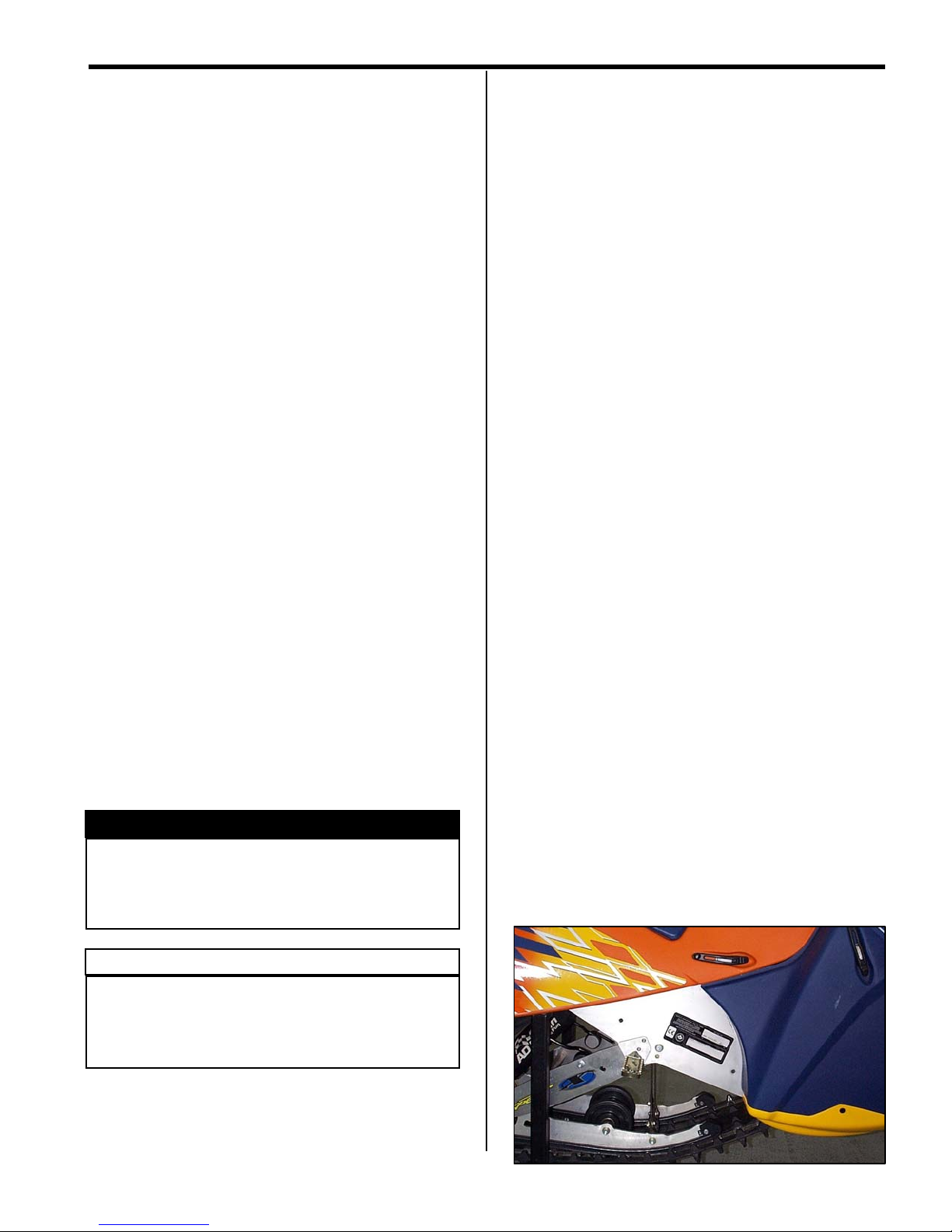
o Descend the belly pan to floor level; most maintenance
can be performed with the belly pan in this position.
However, if it is required to completely remove the belly
pan, remove the single bolt attaching the ski to the fork.
At this point, a second person can lift the front of the
vehicle slightly and the belly pan can be slid out from
underneath.
GENERAL INSTRUCTIONS 1 - 7

PERIODIC MAINTENANCE 2 - 1
V
V
V
V
V
V
V
V
V
V
V
V
V
V-V
V
V
V
V
(
)
V
V
V
y
V
V-V
y
V-V
V
y
V
V
y
)
V
V
V
V
V
V
V-V
V
V-V
V
V
V
V
V
g
V
V
V
V-V
V-V
V
V
V-V
V
g
V
V
V
g g
V
V
V
V
V
●
NOTICE:
Regular inspection and maintenance of the Snow Hawk is of utmost importance. Follow the guidelines in the table
below for optimum vehicle performance. Suggested intervals must be reduced if the vehicle is subjected to severe
usage conditions.
65 Hrs
(yearly)
- A
- F
- R
- C
- R
- A
- A
-
F
- A - R
- A
- A
Item
2.1 Carburetion
2.2 Motor
2.3 Primary transmission
system
2.4 Secondary
transmission system
2.5 Brake system
2.6 Front suspension and
ski
2.7 Rear suspension and
track
2.8 Chassis
2.9 Electrical system
Interval (Hrs)
Fuel lines and connections
Carburetor adjustment
Throttle cable
Air Intake Filter
Carburetor support bracket
Starter cord
Cylinder head bolts
Engine support bolts
Exhaust system
Coolant level
Oil level
Cooling System (hose connections)
Primar
Primar
Primar
Secondary clutch pre-tension
Secondar
Cog sprockets
Torque Limiter
Taper Locks
Brake fluid
Brake pads
Brake microswitch
Front Fork
Fork rubber cushion and bolt
Fork air bleeder screw
Twin axis ski bushin
Ski and runners
Suspension
Shocks
Track
Handlebar bolts
Steering components
Assembly bolts / nuts
Spark plu
Spark plu
Fuse
Headlight projection/aim
Lighting system, stop lamp and
emergency stop switch
water pump oil reservoir
drive belt
and secondary clutch
clutch bolt
drive belt (cog belt
s / nuts
s
ap
Break-in
( ~ 10 Hrs. )
- A - -
---V
- A -
- A V--V
V - A - - V - A
V--V
V--V
F-FF
- A
- A VV - R
V - A - V - A V - A
V--V - C
- A - R -
- A - -
---
VV-V
5 Hrs
--
--
--V - C
--
--
--
--
--
--
--V - A
--F
- A
V - R as needed
--
--
15 Hrs
- R
- A
- A
- A - R
●
NOTICE:
V = Verify, A = Adjust, C = Clean, R = Replace one or several part(s), F = Replace fluid

PERIODIC MAINTENANCE 2 - 2
2.1. CARBURETION
Fuel lines and connections
Check all hoses and connections in order to find and fix leaks
and/or to help prevent them.
Carburetor adjustment
For carburetor adjustment, refer to Chapter 3 - Fuel system
section.
Throttle cable
The throttle cable can be adjusted by setting the adjustment
mechanism on the throttle end of the throttle cable.
Air intake filter
The air intake filter must be cleaned at least once a year, or
more often under severe usage conditions. Clean the filter in a
solution containing a non-flammable cleaning solvant (such as
hot soapy water). Once dry, apply some light engine to the filters
to prevent the infiltration of water and dust.
2.2. ENGINE
Recoil starter cord
Pull gently on the handle to unwind the full length of the cable.
Inspect the cable visually to detect any wear or other damage
that could eventually cause the cord to break.
Cylinder head bolts
Refer to the appropriate procedure in Chapter 7 – Engine
(Cylinders/Head/Base).
Engine support bolts
To carry out this operation, refer to the appropriate procedure in
Chapter 7 – Engine (Cylinders/Head/Base).

Exhaust system
Using a torque wrench, check the torque of the retaining bolts of
the exhaust manifold. Apply a torque of 10 N-m (1 kg-m, 7.4 lbf-
ft).
Then, proceed to a visual inspection of the system to detect any
leak or abnormality in the gasket material.
PERIODIC MAINTENANCE 2 - 3
Cooling system
Inspect the coolant level in the coolant reservoir located on the
MAG side of the vehicle. If the coolant level is below the “Cold”
coolant mark when the vehicle is not warm or has not been
ridden within 30mins or more, add coolant until this line. Check
all of the hoses / hose connections and ensure that there are no
fluid leaks in the system.
Cold
Level

PERIODIC MAINTENANCE 2 - 4
2.3. PRIMARY TRANSMISSION
Primary and secondary clutches
Remove the belt and verify that the sliding half-pulleys of the two
clutches is in good working condition.
To take the belt off, first use the special tool provided to open
the secondary clutch (P/N 529 008 700). Then, slip the belt over
the pulley from rear to front as illustrated. To reinstall the belt,
proceed in the reverse order.
Primary clutch bolt
Check the torque on the primary clutch retaining bolt.
Recommended torque: 90 - 100 N-m (9–10 kg-m, 70 lbf-ft).
For more information, refer to Chapter 8 - Primary
Transmission System.
Pre-tension of the secondary clutch spring
For more information, refer to Chapter 8 - Primary
Transmission System.
Primary transmission belt
Examine the belt. Make sure it is not cracked, frayed or worn in
an abnormal way (uneven wear, wear on one side only, missing
cogs, or cracked material). Abnormal wear of the belt is often
due to mis-alignment of the pulleys, excessive throttle when the
track is frozen, quick acceleration without a preliminary warmup, a scratched or rusted pulley, oil on the belt, or a twisted
replacement belt. If need be, ask an authorized SNOW
HAWK™ dealer for advice.
Measure the width of the belt. Replace if it is less than 31.6 mm
(1.245 in) wide.
For more information, refer to Chapter 8 - Primary
Transmission System.

2.4. SECONDARY TRANSMISSION
Secondary transmission cog belt
Examine the cog belt. Make sure it is not cracked, frayed or
worn in an abnormal way. If in doubt as to the condition of the
belt, replace it with a new one.
Verify the tension of the secondary transmission belt according
to the instructions found in Chapter 9 - Secondary
Transmission System.
PERIODIC MAINTENANCE 2 - 5
Cog Sprockets
Check the appearance of the cog sprockets. Make sure all the
sprockets are there and are free of any accumulated dirt. Clean
if necessary.
Taper-locks
Refer to Chapter 9 - Secondary Transmission System.
2.5. BRAKE SYSTEM
Brake fluid
Check to see if the brake fluid level is above the "mimimum"
mark (see illustration). If not, add fluid.
▼ CAUTION
MIN
Use only DOT 4 brake fluid from a sealed container. Do
not use any other type of brake fluid.

PERIODIC MAINTENANCE 2 - 6
Brake pads
Verify the thickness of the brake pad linings as illustrated. Brake
pads must both be replaced if either one of them shows a
clearance of less than 1 mm (1/32 in.).
●
NOTICE:
For the replacement of brake fluid, refer to Chapter 10 –
Hydraulic Brake System.
2.6. FRONT SUSPENSION AND SKI
Front fork
The air pressure inside the fork legs must be as close as
possible to atmospheric pressure. Therefore, it is advisable to
remove the bleeder screws after every ride to re-establish the
pressure. It should be done more frequently when temperature
variations are greater and more frequent (such as when the
vehicle is stored in a heated garage).
A visual inspection of the fork legs can reveal oil leaks that might
indicate broken main seals. If excessive oil is presest on the
lower fork leg, a seal replacement may be required.
It is recommended to replace the fork oil after the break-in
period and, from then on, after every 15 hours of use. For
details, refer to Chapter 11 – Front Fork and Twin-Axis Ski.
▼ CAUTION
It is advisable to change the fork fluid when preparing the
vehicle for storage. The presence of condensation in the
suspension fluid could cause corrosion during the
storage period.
Twin-Axis Ski and Runners
Verify the torque of all the bolts holding the ski, as well as all the
studs and nuts retaining the runners. Also inspect the
appearance of the runners to detect any wear, distortion, or
broken studs.
2.7. REAR SUSPENSION AND TRACK
Suspension
Verify that all suspension bolts and nuts are well tightened,
especially the four that retain the suspension to the chassis (use
Loctite 243 here) Verify that none of the parts are damaged or
missing.
Verify that the suspension wheel bearings are in good working
order. Check the condition of the suspension limiter straps.
Check the condition of the hyfax.
For more information, refer to Chapter 12 - Rear suspension
and Track.
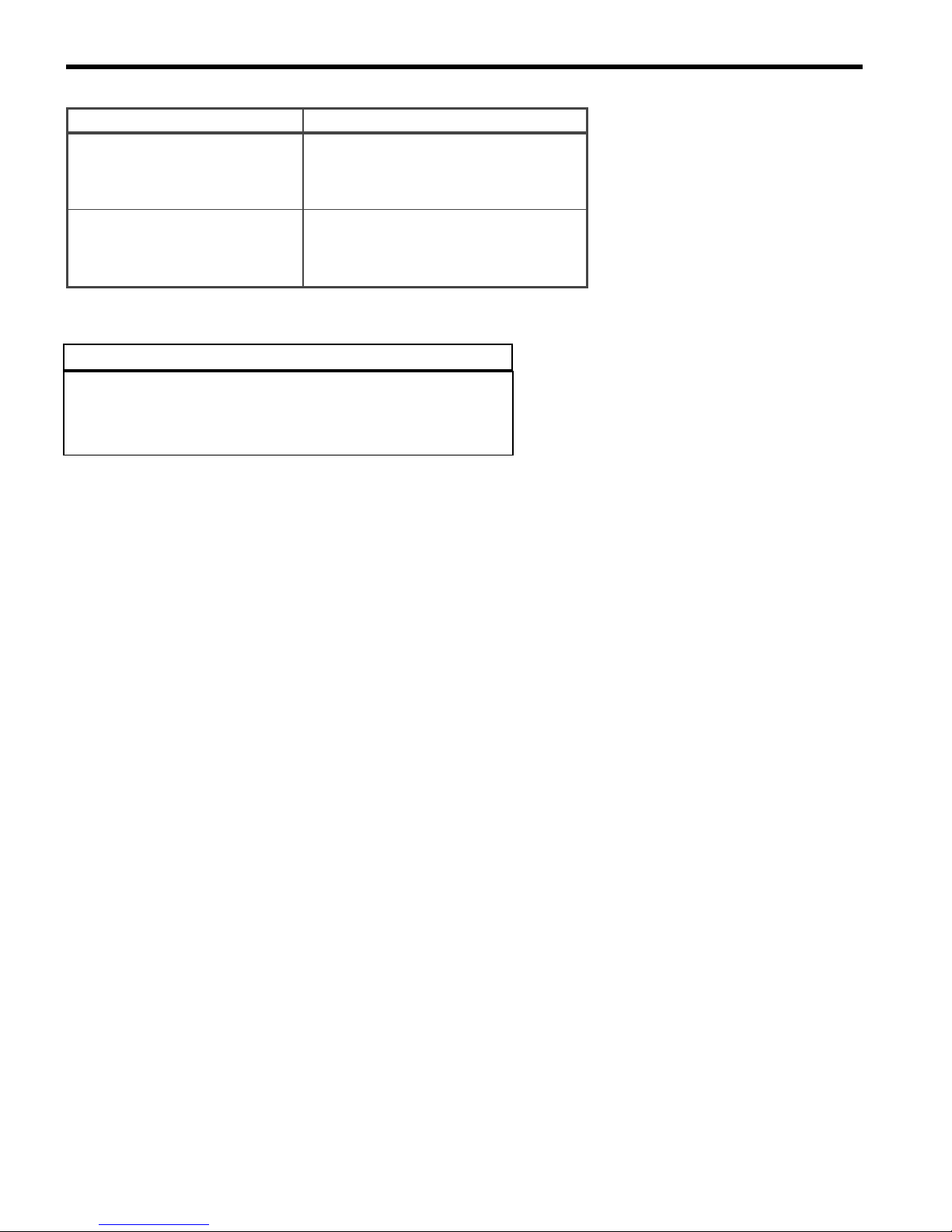
Shock absorbers
Check around the shock guards for the presence of oil leaks.
PERIODIC MAINTENANCE 2 - 7
Shock oil must be replaced once a year. Refer to Chapter 12 Rear suspension and Track.
▼ CAUTION
It is advisable to change the shock fluid when preparing
the vehicle for storage. The presence of condensation in
the suspension fluid could cause corrosion during the
storage period.
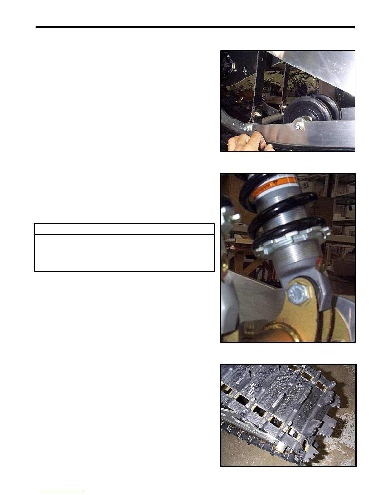
Track
Check the condition, alignment and tension of the track.
With the engine turned off and the rear end of the machine
raised from the ground, rotate the track manually and inspect it
to make sure it is in good working condition. It must not be
cracked and all the lugs must be intact.
●
NOTICE:
For track alignment and tension, refer to Chapter 12 - Rear
Suspension, Shocks and Track.

PERIODIC MAINTENANCE 2 - 8
2.8. CHASSIS AND STEERING
Handlebar mounting bolts
Verify and adjust the torque to 36.5 N-m (3.7 kg-m, 27 lbf-ft),
following a criss-cross order.

Steering mechanism
Verify the condition of the tie rod ends and check for excessive
play in the pivots of the steering system. For alignment, refer to
Chapter 13 – Chassis and Steering.
PERIODIC MAINTENANCE 2 - 9
Assembly
The chassis of the SNOW HAWK is different in that most of the
assembly is done by bolting components rather than welding
them. Therefore, bolts must be checked and tightened as need
be. When doing this, refer to the Torque Table at the end of this
section.
2.9. ELECTRICAL SYSTEM
Spark plug
Check the general condition of the plug, the colour of its
electrodes, carbon deposits, plug gap and possible damage to
the gasket
A NGK BR9ECS spark plug is recommended.
Check the spark plug gap. The suggested gap is 0.45 mm
(0.018").
When tightening the spark plug, the torque must be between 25
and 30 N-m (18 and 21.5 lbf-ft; 2.5 and 3.0 kg-m).
Lean
(light grey)
Normal
(brownish)
Rich
(black)
PERIODIC MAINTENANCE 2 - 10
Porcelain Colour Probable Cause
- Plug Temperature rating is too high
Light Grey (Overheated)
Blackish (Fouled)
- Plug gap too wide
- Air/Fuel mixture too lean
- Stale gasoline
- Plug temperature rating too low
- Plug gap is too small
- Air/Fuel mixture too rich
- Oil/Fuel mixture too rich
▼ CAUTION
The engine may be seriously damaged if the temperature
rating of the spark plug is inadequate.
Refer to the NGK codification on the next page.

Symbols used on the NGK spark plugs
PERIODIC MAINTENANCE 2 - 11

PERIODIC MAINTENANCE 2 - 12
(6)
g
)
g
)
g
y
y
g
g
(4)
Spark plug gap
The suggested gap is 0.45 mm (0.018"). For more information,
refer to Chapter 14 – Electrical System.
Wiring Harness
Electrical wires and connections should be inspected visually to
quickly locate broken wires or faulty connections. For more
information, refer to Chapter 14 – Electrical System.
Headlamp, stop lamp and engine cut-off switch
Before each ride or excursion, it is recommended to verify that
the headlamp, the stop/tail lamp and the engine cut-off switch
are in good working order.
TORQUE TABLE
ITEM N-m kg-m lbf-ft lbf-in
Torque Limiter bolts
Rear Suspension mountin
Rear Suspension lower swin
Recoil starter housin
Primar
Secondar
Taper-Lock installation setscrews
Spark plu
Handlebar mountin
Triple clamp bolts
Fork pivot bolts
Ski runner nuts
Lower clamp nuts
Ski saddle/fork adaptor nut
clutch bolt
clutch bolt
s
bolts
bolts (4
arm bolts (2
bolt
6.20.624.6 55
51 5.1 38 450
90 9 66 792
70.75 62
90 9 66 792
31.7 3.17 23 276
14 1.4 10.4 125
25 2.5 18 216
36.5 3.65 27 324
6.8 0.68 5 60
45 4.5 33 396
19 1.9 14 168
23 2.3 17 204
85 8.5 63 756
For any other bolt or screw that is not mentioned in the list, please refer to the following table.
BOLT
DIAMETER
(MM)
6 101 784151.511132
8 25 2.5 18 216 36 3.6 27 324
10 49 4.9 36 432 72 7.2 53 636
12 85 8.5 63 756 125 12.5 92 1104
N-m kg-m lbf-ft lbf-in N-m kg-m lbf-ft lbf-in
GRADE " 8.8 "
GRADE " 10.9 "

FUEL SYSTEM
FUEL SYSTEM 3 - 1
16
15
12
14
11
11
13
10
9
8
9
8
5
17
35
35
22
24
6
26
19
29
28
3
7
1
27
2
4
21
19
20
34
19
18
23
22
24 25
30
32
33
31
32

FUEL SYSTEM 3 - 2
1 ADB-SH1 1 Fuel tank 31L
2 322111-BKL 1 Gas tank cap
3 907301 1 7/32" gas tank (overflow)
4 SH15 1 Rubber Strap 15"
5ADB-01401Air box
6 508,000,240 1 Intake horn
7 508,000,199 1 Foam
8 508,000,132 2 Intake adaptor
9 508,000,346 2 Gear clamp
10 415,128,729 1 TM40 Carburetors (racked together, as a pair)
11 512,059,835 2 Gear clamp
12 07-0401 1 Throttle cable
13 512,059,110 1 Choke cable
14 512,059,094 1 Plastic nut
15 394,103,300 1 Lock washer (interior tooth)
16 01-0054 1 Twist throttle
17 24-1101 1 Grips (pair)
18 403,901,811 1 Fuel pump
19 414,420,700 3 Spring clamp (green)
20 14-349 1 Tubing
21 415 080 200-1 1 Hose (pump - carburetor)
22 414,415,200 2 Spring clamp (red)
23 415,079,800 1 Impulse hose
24 513,032,979 2 Spring clamp (dark green)
25 513,033,022 1 Hose
26 420,874,370 1 Male connector
27 07-241 1 Fuel filter
28 570,135,100 1 Grommet
29 415 080 200-4 1 Hose (connector - tank)
30 SH 092 1 Short spacer
31 SH 091 1 Long spacer
32 170-103 2 " T " Nut
33 SN328-016 1 Hexagon flange head cap screw ¼-20 x 1 ¼
Fuel System
Part DescriptionsRef. P/N Qty
34 SN328-014 1 Hexagon flange head cap screw ¼-20 x ¾
35 8461k133-1 2 Adhesive rubber pad 1/8" thick x 2" wide

CARBURET0RS (TM 40)
FUEL SYSTEM 3 - 3

FUEL SYSTEM 3 - 4
Carburetors (TM 40)
1 403,138,740 1 TM40 Carburetors (racked together, as a pair)
2 404,162,017 1 Funnel (PTO)
3 404,161,955 2 Screw
4 404,161,945 2 O-ring
5 404,106,200 2 Main jet 380
6 404,161,944 2 Pilot jet 17.5
7 404,162,016 2 Needle 9DHI12-58-3
8 404,162,020 2 Piston Valve 2.0
9 404,137,600 2 Packing
10 404,152,200 2 E-ring
11 404,161,940 2 Gasket
12 404,161,939 2 Cover
13 404,162,006 1 Throttle shaft
14 -XXX- 1 Screw
15 -XXX- 1 Adjustment spring
16 404,161,935 2 O-ring
17 404,161,961 2 O-ring
18 404,161,933 4 Screw
19 404,161,932 2 Float
20 404,161,960 2 Float Body
21 707,200,027 1 E-ring
22 404,162,007 4 Plate
23 404,162,008 2 Holder
24 404,161,928 2 Screw
25 404,162,009 2 Lever
26 404,161,926 2 Ring
27 404,161,925 1 Ring
28 404,161,924 2 Ring
29 404,161,923 4 Screw
30 404,138,300 2 E-ring
31 404,162,010 2 Spring
32 404,162,011 1 Spring
33 404,161,920 2 Screw
34 404,161,919 2 Plate
35 404,162,012 1 Funnel (MAG)
36 404,161,918 1 Spring (PTO)
37 404,161,917 1 Screw (PTO)
38 404,162,022 1 Bracket (PTO)
39 404,162,014 1 Spring
40 404,162,015 1 Throttle shaft
41 404,137,500 1 Adjustment screw
42 404,161,913 1 Spring
Part DescriptionsRef. P/N Qty

FUEL SYSTEM 3 - 5
Ref. P/N Qty Part Descriptions
43 404,161,912 1 Screw
44 404,136,100 1 Screw
Carburetors (TM 40)
45 404,161,911 2 Screw
46 404,161,910 3 Screw
47 404,161,909 2 Lever
48 404,140,000 2 Cap
49 404,136,900 2 Holder guide
50 404,161,908 2 Spring
51 404,161,907 2 Plunger ass'y
52 404,161,906 2 Screw
53 404,161,905 1 Nipple
54 404,162,001 2 Hose
55 404,161,903 2 Screw
56 404,162,000 1 Bracket
57 404,161,901 1 Starter lever
58 404,161,899 2 Cap
59 404,161,898 2 Adjuster
60 404,161,897 2 Spring
61 404,161,896 2 Washer
62 404,161,895 2 Packing
63 404,153,400 2 Nipple
64 404,154,900 2 Cap
65 404,161,894 3 Packing
66 404,103,500 1 Spring
67 404,161,981 1 Shaft ass'y
68 404,161,956 1 Hose
69 404,161,957 2 Clip
70 404,138,800 8 Screw
71 -XXX- 1 Spring
72 270,500,118 2 Packing
73 270,500,095 2 Closure cap

FUEL SYSTEM 3 - 6
REMOVAL
Loosen clamps # 9 retaining air box # 5 to carburetor assembly
and remove air box.
Disconnect the carburetor support block that is located at the
middle-bottom of the carburetor assembly. Pull rearwards on the
upper portion of the block to disconnect it completely.
Loosen clamps # 11 retaining dual carburetor assembly to
carburetor sockets.
Disconnect throttle and choke cables.
▼ CAUTION
Always loosen the LOWER nut when removing the throttle
or choke cable as to avoid disturbing the settings of
either.
Remove dual carburetor assembly, pinch and disconnect fuel
line. Take care to recuperate fuel.
Clamp
Carburetor
support
◆ WARNING
Fuel is flammable and explosive under certain conditions.
Always wipe off any fuel or oil spillage from the vehicle.
Ensure work area is ventilated. Do not smoke or allow
open flames or sparks in the vicinity.
CLEANING AND INSPECTION
The entire carburetor should be cleaned with an all-purpose
cleaner and dried with compressed air before disassembly.
▼ CAUTION
Heavy duty carburetor cleaner may be harmful to the float
material and to the rubber parts, O-ring, seats, etc.
Therefore, it is recommended to remove those parts prior
to cleaning.
Fuel line
Lower nut
Lower nut

▼ CAUTION
Carburetor body and jets should be cleaned with
carburetor cleaner following manufacturer’s instructions.
When jets are very dirty or coated with varnish and gum,
replace them.
◆ WARNING
Solvents with a low flash point such as gasoline,
naphtha, benzol, etc., should not be used as they are
flammable and explosive.
Inspect the condition of the tip of the fuel inlet valve. If the tip is
worn, replace both the valve and its seat.
FUEL SYSTEM 3 - 7
●
NOTICE:
Install only a snowmobile carburetor inlet valve as it is designed
to function with a fuel pump.
Check to see if the throttle slide is worn and replace it if
required.
Check for fuel that may have soaked into float # 8; replace as
necessary.
Check float for cracks or other damage affecting free movement;
replace as necessary.
Inspect throttle and choke cables and housings for any damage.
Replace as necessary.

FUEL SYSTEM 3 - 8
DISASSEMBLY AND RE-ASSEMBLY
●
NOTICE:
To ease the carburetor disassembly and assembly procedure, it
is recommended to use carburetor tool kit (P/N 404 112 000)
# 20 FLOAT BOWL
Unscrew drain screw # 3 and screw # 52. Remove float bowl.
# 19 FLOAT AND NEEDLE VALVE ASS’Y
Unfasten both screws # 18 then, pull out float and needle valve
assembly # 19.
Upon re-assembly, apply Loctite 243 on screw threads.
# 5 MAIN JET
The main jet installed in the carburetor has been selected for a
temperature of - 20°C (0°F) at sea level. Different jetting can be
installed to suit temperature and/or altitude changes. A service
bulletin will give information about calibration according to
altitude and temperature.
Main jet # 5 may be removed without removing float bowl # 20
by first removing drain screw # 3.
# 6 PILOT JET
Use narrow screwdriver from carburetor tool kit (P/N 404 112
000) to unfasten pilot jet # 6.
◆ WARNING
It is critical to the free operation of the throttle slide that
the 2 connecting plates as assembled in one carburetor
be of the exact same length. Always replace the
connecting plates by a pair of new ones that were
matched at the factory for length and discard the old
ones. Simultaneously replace all the plates of the
carburetors of a same rack.
●
NOTICE:
Do not disassemble throttle slide needlessly.

▼ CAUTION
After throttle slide reassembly, proceed with a leak test.
See below for procedure.
# 7 NEEDLE
FUEL SYSTEM 3 - 9
Remove carburetor cover
Loosen needle retainer screw # 33.
# 12.
Fully open throttle and hold in this position for the following step.
Move aside needle retainer # 34.
1. Needle retainer moved aside.
Turn dual carburetor assembly upside down to free needle # 7.
Take care not to loose plastic washer # 9 under needle circlip #
10.
# 2 INTAKE SPICKET
Unscrew throttle slide cover screws # 70.
Open throttle 3/4 wide and hold it there.
Lift throttle slide covers bottom first until they are free from
carburetor bodies. Then, slide them out.
1. Lift bottom first
2. Slide out
After inserting throttle slide cover in place and be-fore installing
screws, ensure O-ring gasket is properly seated in its groove
especially in the area around vent nipple. See illustration at
right.
1. Needle retainer
2. Ensure O-ring gasket is properly seated in nipple area.

FUEL SYSTEM 3 - 10
CARBURETOR ADJUSTMENTS
Adjustments should be performed following this sequence:
- Pilot screw adjustment
- Carburetor synchronization and throttle slide height
(preliminary idle speed adjustment)
- Throttle cable adjustment
- Choke cable adjustment
- Final idle speed adjustment (engine running).
PILOT SCREW ADJUSTMENT
Completely close the pilot screw (until a slight seating resistance
is felt) then back off as specified.
Turning screw clockwise leans mixture and conversely, turning it
counter-clockwise enriches mixture.
Refer to “DIMENSIONS AND TOLERANCES” for the exact
specifications.
1- Idle speed screw
2- Pilot screw (one on each carburetor)
Mikuni TM 40
Pilot jet 17.5 17.5
Air s crew 1.5 turns 1.5 turns
Sli de cutaw ay 2.0 2.0
Needle 9DHI12-58-3 9DHI12-58-3
Main jet 380 380
Fuel le vel N/A N/A
---
Setting
MAG PTO

CARBURETOR SYNCHRONIZATION AND THROTTLE SLIDE
HEIGHT (PRELIMINARY IDLE SPEED ADJUSTMENT)
FUEL SYSTEM 3 - 11
First proceed on PTO carburetor.
Use a drill bit to measure the throttle slide height (see table at
right) on outlet side of carburetor (engine side).
1- Adjust PTO carburetor first
2- Drill bit used as a gauge to measure throttle height
3- Idle speed screw
Adjust by turning idle speed screw # 41.
Throttle slide height
Model
--
(drill bit size)
± 0.1 mm (±0.004'')
1.6 mm ( 0,063'')Snow hawk 600 HO 2004
For MAG carburetor, proceed using the synchronization screw.
Use the same drill bit used for the PTO carburetor to measure
throttle slide height. Turn synchronization screw to adjust.
1- PTO carburetor adjusted first
2- Drill bit used as a gauge to measure throttle height.
3- Synchronization screw
●
NOTICE:
Make sure that throttle cable does not hold the throttle slide.
Loosen cable adjuster accordingly
Final idle speed adjustment (engine running at idle speed)
should be within 1/2 turn of idle speed screw from preliminary
adjustment.
FUEL SYSTEM 3 - 12
INSTALLATION
▼ CAUTION
Never allow throttle slide(s) to snap shut.
To re-install the carburetor, carry out the removal operations in
the reverse order.
Be sure that the carburetor assembly is properly inserted into
the engine intake sockets before tightening the two hose
clamps. (A small amount of white grease can help here) After
this, be sure to reconnect the black plastic carburetor support
block to the lower shaft at the middle-bottom of the carburetor
assembly.
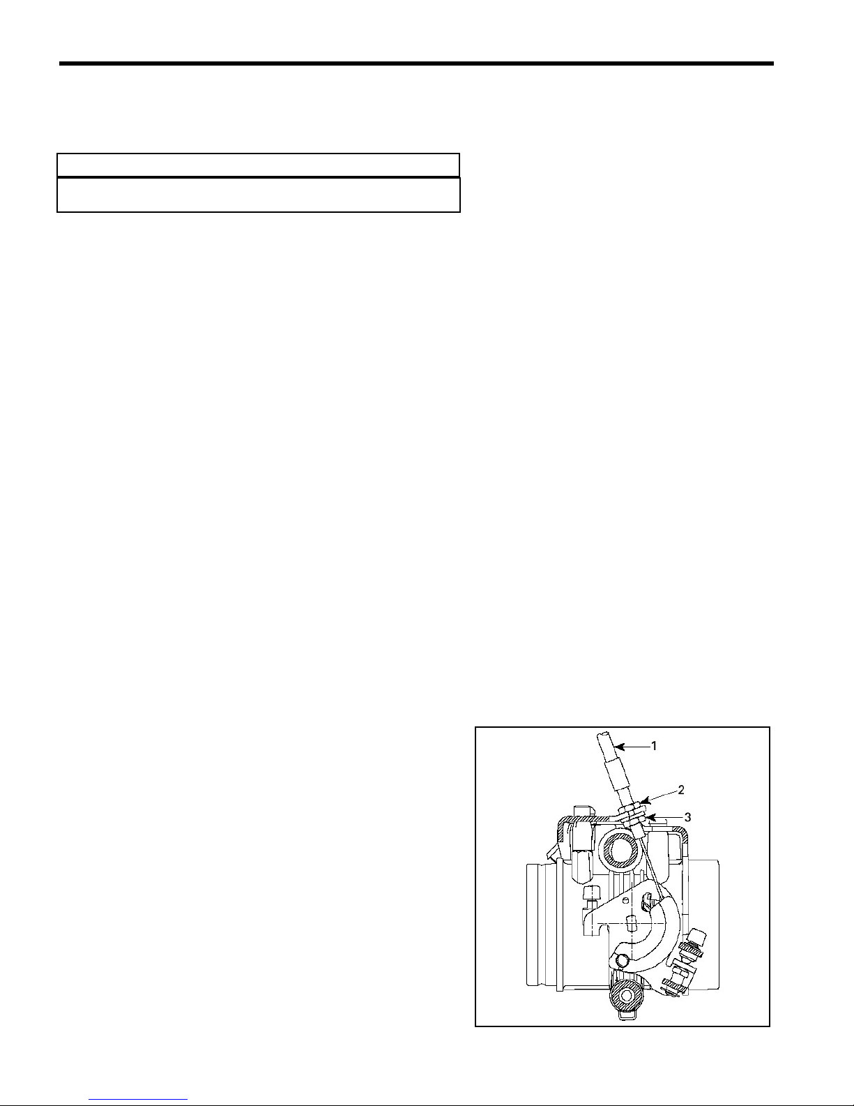
THROTTLE CABLE ADJUSTMENT
Adjust throttle cable as per following procedure:
Loosen throttle cable housing adjusting and locking nuts.
Connect throttle cable barrel to carburetor cam lever # 40.
While holding throttle lever to wide open throttle position, pull on
the throttle cable until mechanism touches the stopper. In this
position, turn cable housing adjusting nut and tighten lock nut.
Also ensure that, when throttle is released to idle position, the
idle adjusting screw end touches its stopper.
1- Throttle cable
2- Adjusting nut
3- Locking nut

CHOKE CABLE ADJUSTMENT
Adjust choke cable as per following procedure:
Loosen choke cable housing adjusting and locking nuts.
Connect choke cable on starter lever # 57.
While choke lever is fully open, pull choke cable until starter
lever reaches the stopper. Tighten cable housing adjusting and
locking nuts in this position.
As a confirmation, the gap between the stopper and the bracket
should be within 0 and 0.5 mm (0 and 1/64 in).
FUEL SYSTEM 3 - 13
A - Within 0 and 0.5 mm (0 and 1/64 in)
Idle Speed Final Adjustment
Start engine and allow it to warm then adjust idle speed to
specifications by turning idle speed screw clockwise to increase
engine speed or counterclockwise to decrease it.
Refer to Chapter 15 – Dimensions and Tolerances for the
specifications.
●
NOTICE:
Do not attempt to set the idle speed by using the pilot screw.
Severe engine dam-age can occur.

FUEL SYSTEM 3 - 14
FUEL PUMP
REMOVAL
Install a hose pincer (P/N 295 000 076) on fuel supply line close
to pump inlet.
Disconnect fuel outlet line(s).
Disconnect impulse line.
Remove screws securing fuel pump to chassis.
PUMP VERIFICATION
Check fuel pump valves operation as follows:
Connect clean plastic tubing to the inlet nipple and alternately
apply pressure and vacuum with pump of leak test kit. The inlet
valve should re-lease with pressure and hold under vacuum.
Repeat the same procedure at the outlet nipple. This time the
outlet valve should hold with pres-sure and also under vacuum.
Check impulse diaphragm and gasket as follows:
Connect clean plastic tubing to the impulse nipple and plug vent
hole on top cover with a finger. Either applies pressure or
vacuum using the pump (P/N 529 021 800) from the Engine leak
tester kit. The diaphragm/gasket must not leak.
1- Pump
2- Plug vent hole

CLEANING AND INSPECTION
Check fuel pump valves operation as follows:
The entire pump should be cleaned with general-purpose
solvent before disassembly.
Fuel pump components should be cleaned in general purpose
solvent and dried with compressed air.
◆ WARNING
Solvent with a low flash point such as gasoline, naphtha,
benzol, etc., should not be used as each is flammable and
explosive.
FUEL SYSTEM 3 - 15
Inspect diaphragm. The pumping area should be free of holes,
tears or imperfections. Replace as needed.
INSTALLATION
Inverse removal procedure.
◆ WARNING
Perform a pressure test to ensure there is no leak in the
fuel system.

ENGINE REMOVAL 4-1
ENGINE REMOVAL
Unfasten or remove the following parts of the vehicle:
Remove the hood, bellypan and rear module from the vehicle.
Removing the bellypan will require that you remove the ski as
well.
Exhaust Pipe
o Remove the hose clamp retaining the exhaust pipe as
well as the two forward brackets (P/N’s SH032L and
SH032R).
o Remove the four springs that hold the exhaust pipe tight
against the Y-manifold.
o Remove the two exhaust springs that hold the exhaust
pipe tight with the exhaust canister.
o Now free, pull the exhaust pipe forward to remove the
pipe completely from the vehicle.
o Plug the outlet of the Y-manifold with a clean cloth.

Front Fork
ENGINE REMOVAL 4-2
o Unfasten the tie rod end which connects the steering
column to the upper triple clamp.
o Unfasten the two fork pivot bolts that retain the fork to
the vehicle. The upper bolt is shown at right, the other
is directly below it.
●
NOTICE:
Use a crate or box to support to support the vehicle just
under the drive sprockets when removing the fork.
Recoil Starter
o Using a flat-head screwdriver, push the knot out of the
recess in the starter handle. Since it is often easier, cut
the cord just before the knot while holding the cord
securely such that it does not slip and go into the recoil
housing. Make a new knot in the cord once the starter
handle has been removed to prevent this from
happening.
Fork Pivot Bolt

ENGINE REMOVAL 4-3
o Make a knot as shown at right.
Secondary Clutch
o Open the secondary clutch using the the spacer tool
(P/N 529 008 700). For more details, see Chapter 8 –
Primary Transmission System.
o Remove the bolt retaining the secondary clutch to the
jackshaft and then slide the secondary off the jackshaft
at the same time removing the drive belt.
o Using the primary clutch holder tool (P/N 529 027 600),
remove the primary clutch bolt.
o Using the primary clutch puller (P/N 529 022 400)
remove the primay clutch from the engine.
Fuel Tank
o Remove the rubber latch retaining the fuel tank and
place it as shown on the right to have free access to the
airbox and carburetors.

Airbox
o Loosen the too hose clamps that fasten the air box to
the rear of the carburetors and remove the airbox
completely.
Carburetors
o Unfasten the black plastic clip that supports the bottom
of the carburetors. Push the top of it forward to snap it
out of place. Rotate it sufficiently to allow clearance.
ENGINE REMOVAL 4-4
o Loosen the two hose clamps that fasten the carburetors
to the engine intake boots and then remove the
carburetors completely, as a pair.
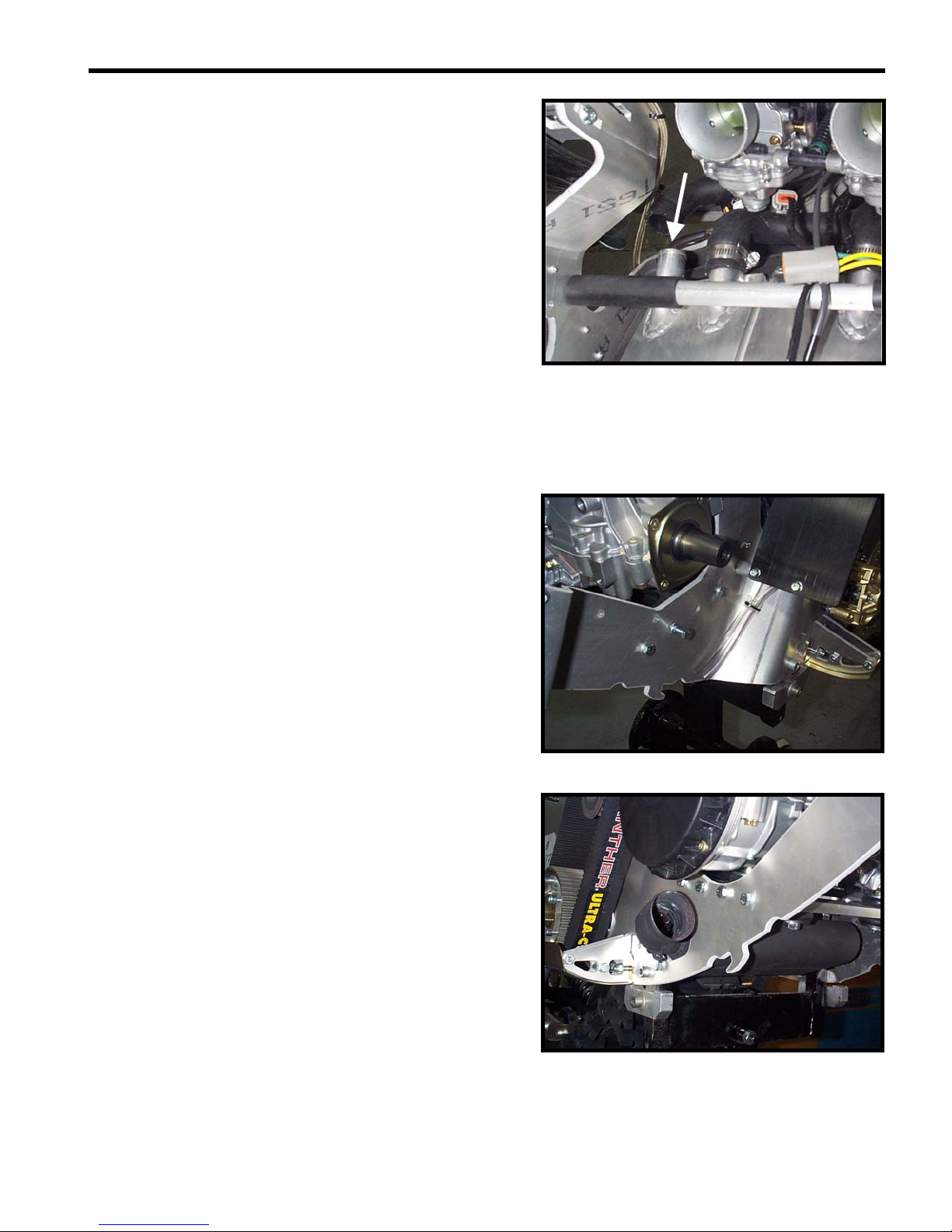
Engine Connector
o Cut the tie-wrap and disconnect the two-place housing
that connects the Crank Position Sensor (CPS) to the
wiring harness (blue and white/yellow wires). This
connector is located just above the jackshaft, near the
ignition coil and the water pump oil reservoir.
o The engine-side of the Crank Position Sensor (CPS)
wire then passes down the height of the chassis –
towards the magneto – and is attached to the tube that
goes from the water pump oil reservoir to the water
pump itself via a tie-wrap. Cut this tie-wrap as well.

ENGINE REMOVAL 4-5
o Cut the tie-wraps that secure the wires from the engine
to the voltage regulator. Then disconnect the four-place
housing (yellow, yellow and yellow wires) and the twoplace housing (green and black wires) that is next to the
four-place housing.
o Unplug the two wires from the two temperature sensors
located at the rear of the head of the engine.
Impulse Hose
o Disconnect the impulse hose from the crankcase of the
engine.

Water Pump Oil Resrevoir
ENGINE REMOVAL 4-6
o Using a drill and a 3/16 in. bit, drill out the two rivets that
secure the water pump oil reservoir to the MAG side
chassis.
o Cut the tie-wrap that secures the choke cable to the oil
reservoir hose.
Cooling System
o Loosen the hose clamp that holds the forward cooling
hose to the water pump housing inlet at the front of the
engine. With a bucket below this point, let the coolant
drain from the system completely.
o Loosen the hose clamp on the reservoir end of the short
hose that runs from the head to the reservoir and
disconnect the hose from the reservoir, as shown at
right.
ENGINE REMOVAL 4-7
o Loosen the hose clamp farthest towards the PTO side
on the PTO side heat exchanger and disconnect the
hose there. This hose runs from the head of the engine
to the inlet of the tunnel-mounted heat exchangers and
should remain connected to the engine when removing.
o Now that all of the peripheral equipment has been
disconnected, unscrew and remove the 4 bolts (per
side) that secure the engine plate to each side of the
chassis.
o PTO side bolts (x 4)
o MAG side bolts (x 4)
o Now the engine can be completely removed from the
vehicle.

Re-Installating Engine
To re-install the engine, follow the instructions above in the
reverse order. However, pay close attention to the following
details :
o Ensure that the 4 (per side) engine plate bolts are well
torqued to 37 N-m (27lbf-ft, 325 lbf-in). Loctite 243 is
recommended here.
o Ensure the correct alignment of the clutches and the
preload/deflection of the drive belt.
o Ensure that each cable, wire and hose is properly
connected and its original routing is used. (See Chapter
17 – Wire, Cable and Hose Routing for more details.)
o Ensure that each coolant line is re-installed using the
original routing and that each hose clamp is well
tightened.
o Re-fill the coolant reservoir to the Cold Level line before
attempting to start the vehicle. It is recommended to
elevate the front of the vehicle about 12 in. off the
ground when adding coolant to the system to ensure
that all of the air bubbles will escape. See Chapter 6 –
Cooling System for more details.
ENGINE REMOVAL 4-8

REWIND STARTER
REWIND STARTER 5 - 1

REWIND STARTER 5 - 2
REWIND STARTER
1 420810865 1 Connecting flange
2 420241236 4 Socket head screw M6 x 16
3-12 420889764 1 Rewind starter
3 420811404 1 Starter housing
4 420939115 1 Rewind spring
5 420852286 1 Rope sheave
6 412500200 1 Starter rope (2200mm)
7 420852297 1 Pawl
8 420852305 1 Pawl lock
9 420847925 1 Stage sleeve
10 420250400 1 O-ring
11 420852520 1 Lock ring
12 420845560 1 Locking element
13 - 1 Positioning pin
14 420941256 4 Hex collar screw M6 x 20
15 420899763 @ Molykote PG 54, 10g
16 293530011 @ Sealant, Sikaflex black # 221
17 572084400 1 Starter grip
Part descriptionsRef. P/N Qty

INSPECTION
●
NOTICE:
Due to dust accumulation, rewind starter must be periodically
cleaned, inspected and re-lubricated.
◆ CAUTION
It is of the utmost importance that the rewind starter spring be
lubricated periodically using Molykote PG 54 (P/N 420 899
763). Otherwise, rewind starter component life will be
shortened and/or rewind starter will not operate properly under
very cold temperatures.
o Check if rope # 6 is fraying, replace if so.
o When pulling starter grip, mechanism must engage
within 30 cm (1 ft) of rope pulled. If not, disassemble
rewind starter, clean and check for damaged plastic
parts. Replace as required, lubricate, reassemble and
recheck. Always replace O-ring # 10 every time rewind
starter is disassemble.
REWIND STARTER 5 - 3
o When releasing starter grip, it must return to its stopper
and stay against it. If not, check for proper spring
preload or damages. Readjust or replace as required.
O When pulling starter grip 10 times in a row, it must
return freely. If not, check for damaged parts or lack of
lubrication. Replace parts or lubricate accordingly.
REMOVAL
o Using a small screwdriver, extract rope knot from starter
grip # 17. Cut rope close to knot. Tie a knot near starter.
o Remove screw # 14 securing rewind starter to engine
then remove rewind starter.
REWIND STARTER 5 - 4
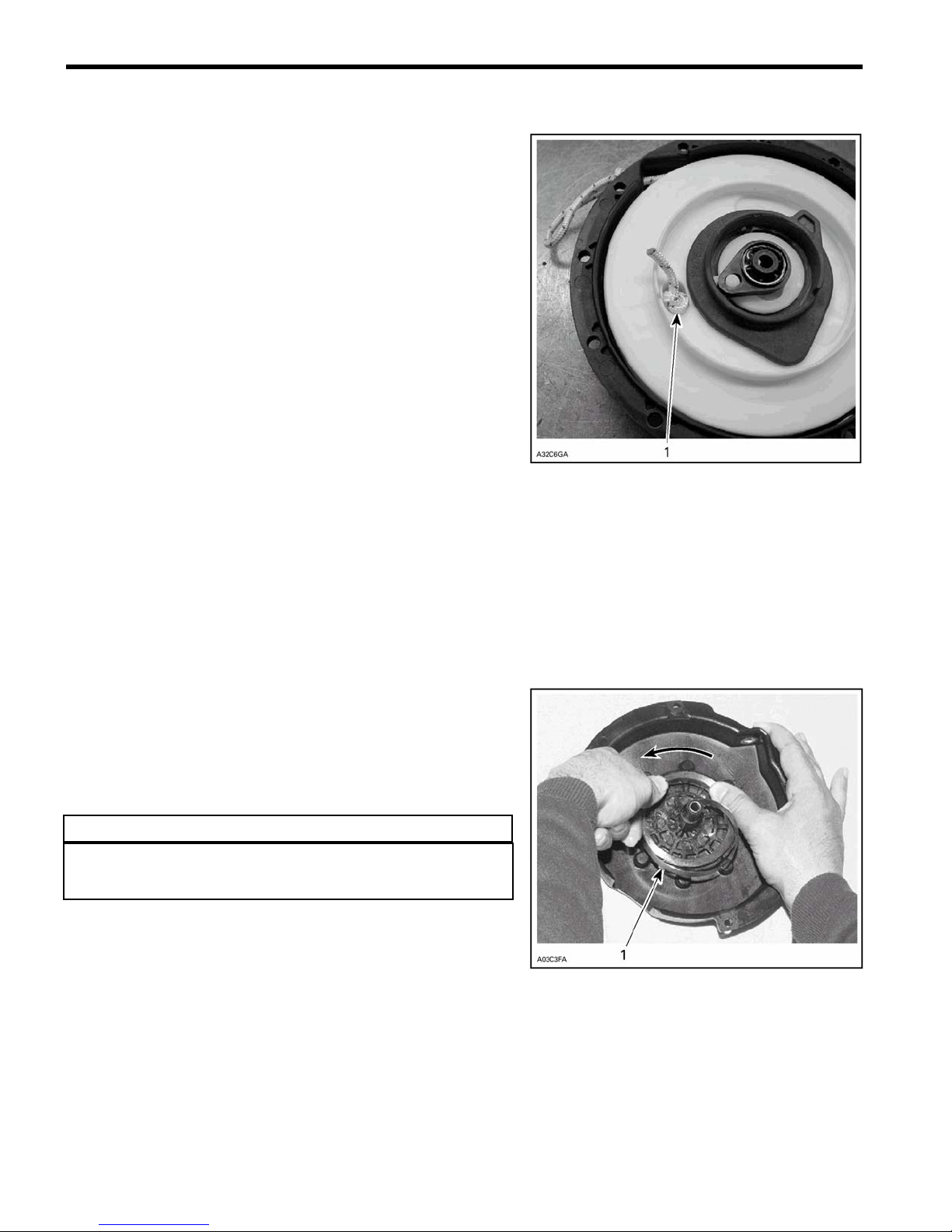
ROPE REPLACEMENT
o Pull out rope. Hold rewind starter in a vise. Slide rope
and untie the knot. Pull out the rope completely.
1) Knot to be untied.
●
NOTICE:
When rope is completely pulled out, spring preload is 4 ½ turns.
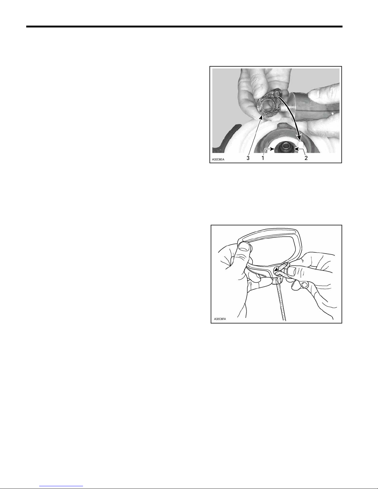
DISASSEMBLY
o Undo knot previously tied at removal. Let sheave get
free to release spring preload.
o Cut locking element # 12 and discard. Remove lock ring
# 11, O-ring # 10, stepped sleeve # 9, Pawl lock # 8 and
Pawl # 7.
o Remove sheave # 5 from starter housing # 3. Hold the
spring with a screwdriver.
o Pull out knot and then pull out rope # 6.
ASSEMBLY
At assembly, position spring # 4 outer end into spring guide
notch then wind the spring counter clockwise into guide.
▼ WARNING
Since the spring is tightly wound inside the guide it may fly out
when rewind is handled. Always handle with care.
1) Outer end into guide notch

◆ CAUTION
It is of the utmost importance that the rewind starter spring be
lubricated periodically using Molykote PG 54 (P/N 420 899
763). Otherwise, rewind starter component life will be
shortened and/or rewind starter will not operate properly under
very cold temperatures.
o Lubricate spring assembly and 1cm (1/2 in) wide on
bottom of housing with Molykote PG 54.
1) Molykote PG 54
◆ CAUTION
REWIND STARTER 5 - 5
The use of standard multi-purpose grease could result in
rewing starter malfunction.
o To install rope # 6, insert rope into sheave # 5 orifice
and lock it by making a knot, leaving behind a free
portion of about 25 mm in length. Fuse rope end with a
lit match and insert it into sheave.
o Free portion inserted into the sheave.
o Lubricate housing post with silicone compound grease.
Install sheave.
To adjust cord tension:
o Wind rope on the sheave and place the rope sheave
into the starter housing making sure that the sheave hub
notch engages in the rewind spring hook.
o Rotate the sheave counter-clockwise until rope end is
accessible through rope exit hole. This will give ½ turn
of preload.
o Pull the rope out of the starter housing and temporarily
make a knot to hold it.
REWIND STARTER 5 - 6
o Lubricate pawl # 7 with Molykote PG 54 (P/N 420 899
763) then install over rope sheave.
o Lubricate pawl lock # 8 with Molykote PG 54. Install
over pawl.
o Instal stepped sleeve # 9 with its sleeve first. Lubricate a
new O-ring # 10 and lock ring # 11 whit Molykote PG
54. Install over pawl lock.
1) Stepped sleeve
2) O-ring
3) Lock ring
o Install the locking element nut # 12.
INSTALLATION
o Fuse rope end with a lit match.
o Thread starter rope # 6 over guide pulleys and through
eye bolt.
o Reinstall rewind starter assembly on engine.
o Pass rope through starter grip # 17 and tie a knot in the
rope end. Insert rope end down and pull the starter grip
over the knot.

COOLING SYSTEM
COOLING SYSTEM 6 - 1
7
12
2
1
12
12
11
10
12
3
12
9
12
4
6
12
5
12
12
8

COOLING SYSTEM 6 - 2
Cooling System
1 509000281 1 Coolant reservoir
2 509000187 1 Closure cap
3 SH-108SA 1 MAG side heat exchanger
4 SH-109SA 1 PTO side heat exchanger
5 SH-093 1 Coolant tube #4
6 SH-094 1 Coolant tube #3
7 SH-095 1 Coolant tube #1
8 SH-096 1 Coolant tube #5
9 SH-097 1 Coolant tube #2
10 - 1 Overflow tube
11 414554800 1 Spring clamp (black)
12 408800400 10 Hose clamp (geared)
- 278001016 1 Temperature sensor (Bosch, Blue, MAG side)
- 512047000 1 Temperature sensor (Indebras, Black, PTO side)
- 420922517 1
- 420931272 1 Thermostat sealing ring
Thermostat (42
Part descriptionsRef. P/N Qty
o
)

◆ WARNING
This vehicle is equipped with a liquid cooling system.
ALWAYS ride with the rear deflector pad installed and in
conditions where there is enough snow to properly cool
the engine. If the red temperature light on the steering
column should ever illuminate, stop immediately and let
the vehicle cool down, and then find some snow. NEVER
continue to operate the vehicle with the temperature light
illuminated as severe engine damage will occur.
COOLING SYSTEM LEAK TEST
o Install special radiator cap (P/N 529021400) included in
engine leak tester kit (P/N 861749100) on coolant tank.
o Install hose pincher (P/N 295000076) on the overflow
hose. Using pump also included in the kit and
pressurize the entire system through the coolant
reservoir to 100 kPa (15 PSI).
o Check all hoses and cylinder/base for coolant leaks.
Spray all connections with a soapy water solution and
look for air bubbles.
INSPECTION
Check the general condition of hoses and clamp tightness.
DRAINING THE SYSTEM
To drain the cooling system:
o Siphon the coolant mixture from the coolant tank.
o Disconnect the hose at the water pump inlet housing to
drain coolant from engine.
o When the coolant level is low enough, lift the rear
of the vehicle to drain the heat exchangers.
COOLING SYSTEM 6 - 3
◆ WARNING
Never drain or refill the cooling system when the engine
is hot.
DISASSEMBLY AND ASSEMBLY
Temperature sensors:
o Apply Loctite 592 (P/N 413 702 300) thread sealant to
temperature sensor threads to avoid leakage.
COOLING SYSTEM 6 - 4
Pressure Cap (No. 2):
o Check if the cap pressurizes the system. If not,
install a new 90 kPa (13 PSI) cap (do not exceed this
pressure).
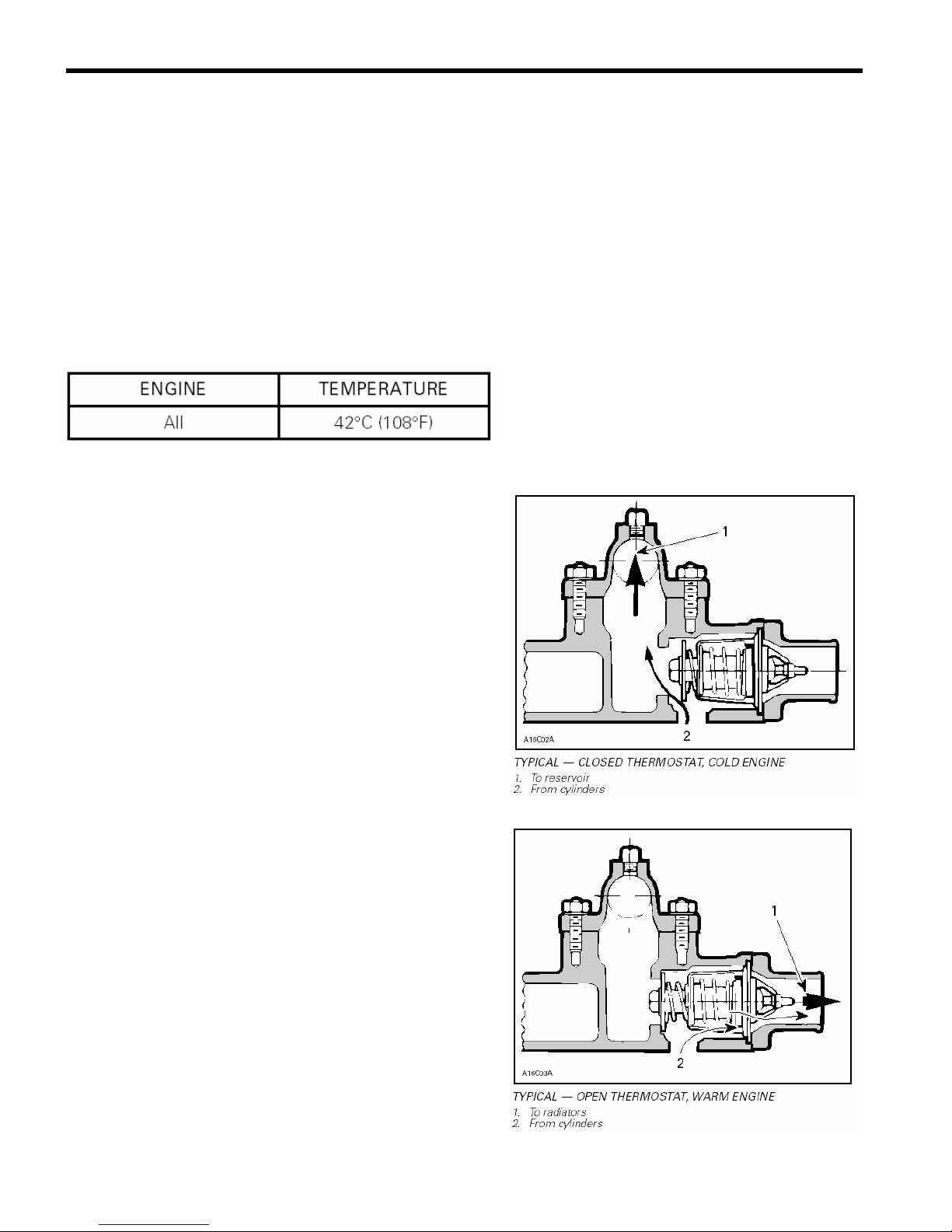
Thermostat:
To check the thermostat, put it in a basin of water and gradually
heat it. The thermostat should start to open when water
temperature nears 42°C (108°F). It will be almost fully open at
50°C (122°F).
The thermostat is a double action type:
(1) Its function is to give faster warm up of the engine by
controlling a circuit; water pump — engine — coolant
tank. This is done by bypassing the heat exchanger
radiator circuit and using what it called a short circuit
during warm up, i.e. before the coolant temperature
reaches 42°C (108°F).
(2) When the liquid is warmed enough, the thermostat
progressively opens the circuit; water pump
— engine — heat exchangers — coolant tank to keep
the liquid at the desired temperature. (See the
diagram of the exploded view on page 6-1).
These 2 functions have the advantage of preventing
a massive entry of cold water into the engine.
COOLING SYSTEM REFILLING PROCEDURE
▼ CAUTION
To prevent the formation of corrosion or freezing, always
re-fill the system with the recommended premixed
coolant.
REFILLING PROCEDURE
●
NOTICE:
Use the 50/50 premixed coolant rated for -37°C (- 35°F) (P/N 293
600 038).
o Do not reinstall pressure cap.
o With engine cold, refill coolant tank up to COLD LEVEL
line.
o Start engine. Refill up to line while engine is idling until
rear heat exchangers are warm to the touch (about 4 to 5
minutes).
o Always monitor coolant level while filling tank to avoid
emptying.
o Install pressure cap.
o Lift rear of vehicle and support it safely.
o Blip the throttle 3 - 4 times to bring engine speed to 7000
RPM.
o Apply the brake to stop the track.
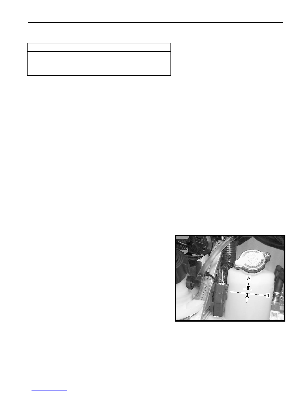
o Lower vehicle back on ground and add coolant up to 15
mm (1/2 in) above the COLD LEVEL line, as shown at
right.
o Lift front of vehicle approximately 60 cm (24 in) and
support it safely. Let the vehicle idle for two minutes like
this
o Put the vehicle back on the ground and add coolant up to
15 mm (1/2 in) above the COLD LEVEL line.
o When the engine has completely cooled down, recheck
coolant level in coolant tank and refill up to the line if
needed.
o Check for coolant mixture freezing point. The
specification is - 37°C (- 35°F). Adjust as necessary.
COOLING SYSTEM 6 - 5
ENGINE / BOTTOM END
ENGINE (CYLINDERS / HEAD / BASE) 7 - 1
49
31
10
45
42
41
9
40
39
44
7
43
47
46
22
36
33
19
26
35
23
21
25
24
18
48
34
13
3
30
6
29
13
29 N-m ( 21.5 lbf-ft
3.0 kg-m, 258 lbf-in)
8
2
28
11
1-12
5
12
4
20
17
8
37
15
16
14-20
38
32

ENGINE (CYLINDERS / HEAD / BASE) 7 - 2
8
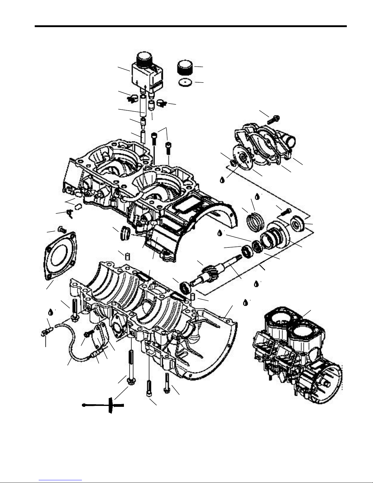
Engine / Bottom End
Ref. P/N Qty Part Descriptions
1-12 420889083 1 Crankcase ass‘y
2 420640836 10 Hex. collar screw M8 x 75
3 420640431 6 Hex. collar screw M8 x 45
4 420640311 2 Hex. collar screw M6 x 45
5 205063044 1 Socket head screw M6 x 30
6 420941925 2 Screw M5 x 16
7 420840401 2 Socket head screw M6 x 22
8 290632010 2 Dowel pin
9 420860965 1 Cable Grommet
10 420960770 2 Cap
11 420960777 1 Cap
12 420232100 1 Ball Bearing
13 420956510 2 Check Valve
14-20 420837421 1 Water Pump Assy
15 - 1 Step Collar
16 420230195 1 Oil Seal
17 420232100 1 Ball Bearing
18 420650370 1 Oil Seal
19 420950890 2 O-Ring
20 - 1 Water Pump Shaft
21 420840511 2 Socket Head Screw M5 x 16
22 420227945 1 Washer
23 420222505 1 Water impeller
24 420931810 1 Gasket
25 420922630 1 Water pump housing
26 420240031 6 Hex screw M6 x 25
27 420230400 1 O-ring
28 420931565 1 Gasket
29 420810825 1 Block-off plate
30 414413800 - Oil Line
31 420938190 1 Clamp
32 420059340 - Short Block Assy 593HO
33 293800060 10mL Loctite 243
34 413711400 10mL Loctite 648
35 413707000 - Molykote 111
36 420899271 400g Petamo Grease, GHY133N
37 420297906 30mL Sealing compound
3
413802900 12 x 1L Injection Oil

ENGINE (CYLINDERS / HEAD / BASE) 7 - 3
Engine / Bottom End
Ref. P/N Qty Part Descriptions
39 420974535 - Oil Line
40 420874370 1 Reducer fitting
41 420956239 - Oil Line
42 420951260 1 Clamp
43 420951240 1 Clamp
44 420960279 1 Cap
45-47 420956240 1 Oil Reservoir Assy
46 420850350 1 Rubber Gasket
47 420956250 1 Oil Cap
48 420812420 1 Oil Seal Cover
49 420941430 4 Countersunk screw M6 x 20

ENGINE (CYLINDERS / HEAD / BASE) 7 - 4
ENGINE / CRANKSHAFT AND PISTONS

ENGINE (CYLINDERS / HEAD / BASE) 7 - 5
Engine / Crankshaft and Pistons
Ref. P/N Qty Part Descriptions
1 - 9 420889090 1 Crankshaft Assy
2 420832635 1 Brg. 6207
3 420832575 1 Brg. 6207
4 420931792 1 Oil Seal
5 420832606 1 Brg.
6 420926190 1 Washer
7 420832600 1 Brg.
8 420931285 1 Oil Seal
9 420246015 1 Woodruff key
10 420945759 1 Lock Washer 22mm
11 420842230 1 Hex Nut M22
12 420832425 2 Needle Brg.
13-14 420889181 2 Piston Assy (71.89mm)
14 420815290 2 Semi-trapez ring
15 420916410 2 Gudgeon pin
16 420845106 4 Piston Circlip
17 420832575 1 Brg. 6207
18 420931455 2 Oil Seal
19 420834355 1 Central Gear (15 teeth)
20 420819709 1 Crankshaft (PTO section)
21 420819739 1 Crankshaft (MAG section)
22 420889093 1 Rod Repair Kit (MAG)
- 420889094 1 Rod Repair Kit (PTO)
23 293800060 10mL Loctite 243
24 293800070 8oz Loctite 767, anti-seize lubricant
25 413711400 10mL Loctite 648
26 420899271 400g Petamo Grease, GHY133N
27 293550021 50g Isoflex Grease
28 413802900 12 x 1L Injection Oil

ENGINE (CYLINDERS / HEAD / BASE) 7 - 6
ENGINE / TOP END

ENGINE (CYLINDERS / HEAD / BASE) 7 - 7
5
5
Ref. P/N Qty Part Descriptions
Engine / Top End
1 420931895 1 Base Gasket 0.8 mm
420931894 - Base Gasket 0.7 mm
420931892 - Base Gasket 0.6 mm
420931893 - Base Gasket 0.5 mm
2 420613710 2 Nicasil Cylinder
3 420854650 2 Exhaust Valve Guillotine
4 420430110 2 O-ring
5 420931542 2 Gasket
6 420854455 2 Valve Housing
7 205062544 4 Socket head screw M6 x 25
8 420260729 2 Bellows
9 420838253 2 Spring Clamp
10 420854449 2 Exhaust Valve
11 290239048 2 Hose Spring
12 420239944 2 Spring
13 290911558 2 Valve Cover
14 420430220 2 O-ring
15 420241221 2 Adjuster Screw
16 420241270 4 Screw M5 X 25
17 420640524 4 Hex collar screw M10 x 80
18 420640534 4 Hex collar screw M10 x 120
19 420931590 2 Rubber Ring Seal
20 293300026 2 O-ring
21 420613700 1 Cylinder Head (Silver)
22 290950320 1 O-ring
23 420430782 2 O-ring
24 420923460 1 Cylinder Head Cover (Silver)
25 420841306 10 Hex collar screw M8 x 65
26 420941621 2 Hex collar screw M8 x 56.5
o
27 420922517 1
Thermostat (42
C)
28 420931272 1 Sealing Ring
29 420922025 1 Outlet Socket
30 420941250 3 Screw M6 x 20
31 420850338 1 Gasket
32 420922062 1 Curved Neck Outlet
33 420240480 1 Plug Screw 1/8-27 NPT
34 420941451 1 Hex collar screw M8 x 40
35-38 420867879 2 Intake Socket Assy
36 420924680 4 Reed Petal
37 420924695 4 Reed Petal Stop
38 42094121
12 Screw M3 x

ENGINE (CYLINDERS / HEAD / BASE) 7 - 8
Engine / Top End
Ref. P/N Qty Part Descriptions
39 420941925 12 Screw M5 x 16
40 420850552 2 Gasket
41 420673070 1 Exhaust Manifold
42 420889920 1 Engine Gasket Set
43 420889925 1 Cyliinder Gasket Set
44 420297906 30mL Sealing Compound
45 293800038 50mL Loctite 518

TOP END
●
NOTICE:
The engine must be removed from the chassis to carry out the
following operations. See Chapter 4 – Engine Removal for
details.
TROUBLESHOOTING
Before completely disassembling the engine, check airtightness.
Refer to the section named LEAK TEST AND ENGINE
DIMENSION MEASUREMENT at the end of this chapter.
CLEANING
o Discard all gaskets and O-rings.
o Clean all metal components in a non-ferrous metal
cleaner.
o Scrape off carbon formation from cylinder exhaust
port cylinder head and piston dome using a wooden
spatula.
●
NOTICE:
The letters “AUS” (over an arrow on the piston dome) must be
visible after cleaning.
o Clean the piston ring groove with a groove cleaner
tool or with a piece of broken ring.
DISASSEMBLY
RAVE System
ENGINE (CYLINDERS / HEAD / BASE) 7 - 9
●
NOTICE:
RAVE stands for Rotax Adjustable Variable Exhaust.
o Remove spring clip or screws no. 16, cover no. 13
and spring no. 12.
o Remove spring no. 11.
o Unscrew valve piston no. 10.
o Remove bellows no. 8 and spring no. 9.
o Remove cylindrical screws. Remove valve housing
no. 13.
o Pull out exhaust valve no. 3. (see right)
2, Cylinder
Remove spark plugs, coolant outlet no. 32. Unscrew
cylinder head cover no. 24 then cylinder
head no. 21.
13, Piston
Place a clean cloth or rubber pad (P/N 529 023 400)
over crankcase. Then with a pointed tool inserted
in piston notch, remove both circlips no. 16 from
piston no. 13.

ENGINE (CYLINDERS / HEAD / BASE) 7 - 10
All engines are equipped with cageless piston pin
Bearings, as shown at right.
Once the head and cylinder(s) has been removed, Use piston pin
puller (P/N 529 035 503) along with 20 mm sleeve kit (P/N 529
035 542). Use also a locating sleeve.
●
NOTICE:
The locating sleeve is the same that contains new cageless
bearing.
Insert piston pin puller (P/N 529 035 503) making
sure it sits squarely against piston as shown at right.
Install sleeve (1) then shouldered sleeve (2) over puller
rod as shown at right.
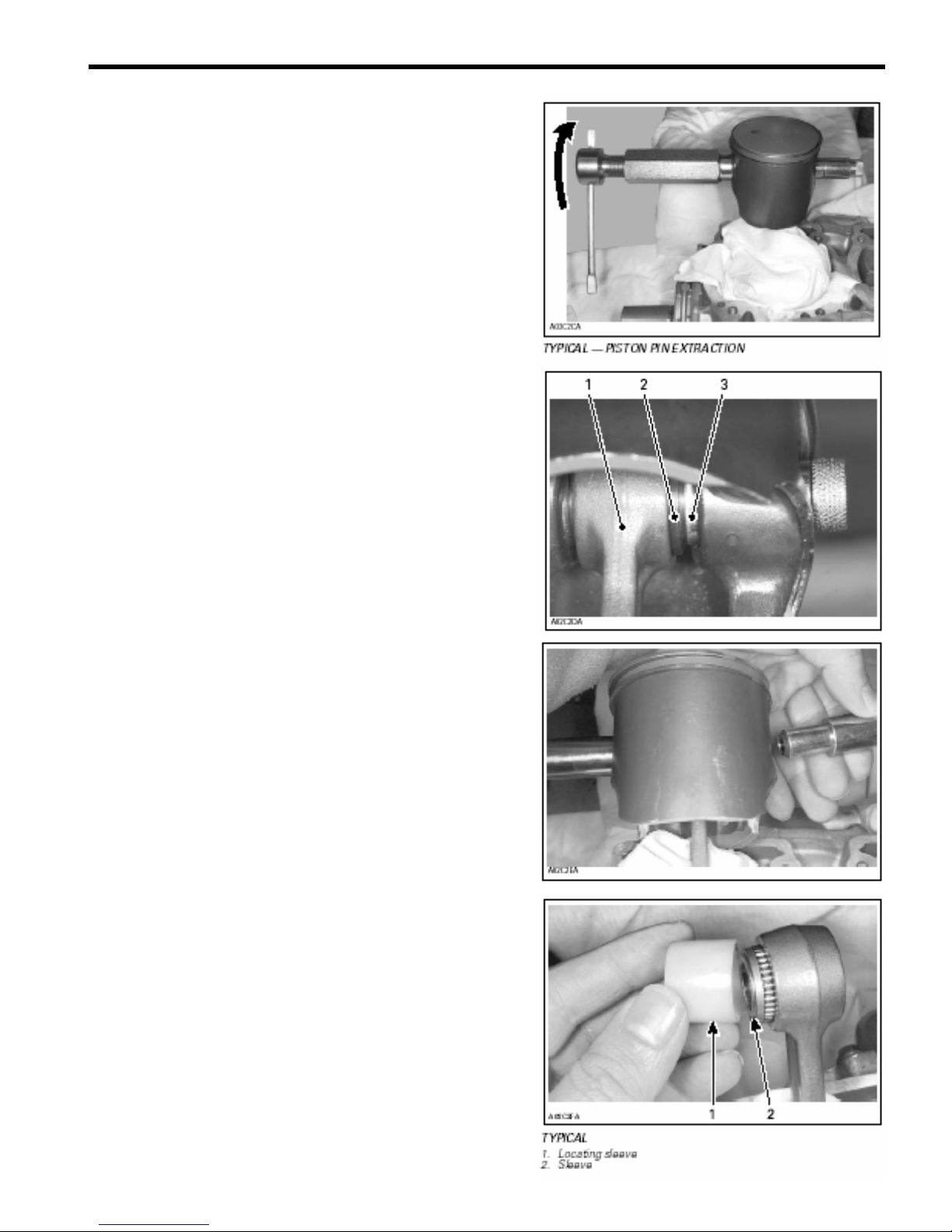
Screw in (LH threads) extracting nut.
Pull out piston pin no. 15 by unscrewing puller until shouldered
sleeve end is flush with thrust washer of piston pin bearing.
Remove puller. Pull out shouldered sleeve carefully.
Remove piston from connecting rod.
Install locating sleeve. Then push the needle bearings, thrust
washers and sleeve into the upper connecting rod journal
ENGINE (CYLINDERS / HEAD / BASE) 7 - 11
ENGINE (CYLINDERS / HEAD / BASE) 7 - 12
INSPECTION
●
NOTICE:
For details, Refer to LEAK TEST AND ENGINE DIMENSIONS
MEASUREMENT AT THE END OF THIS CHAPTER.
RAVE System
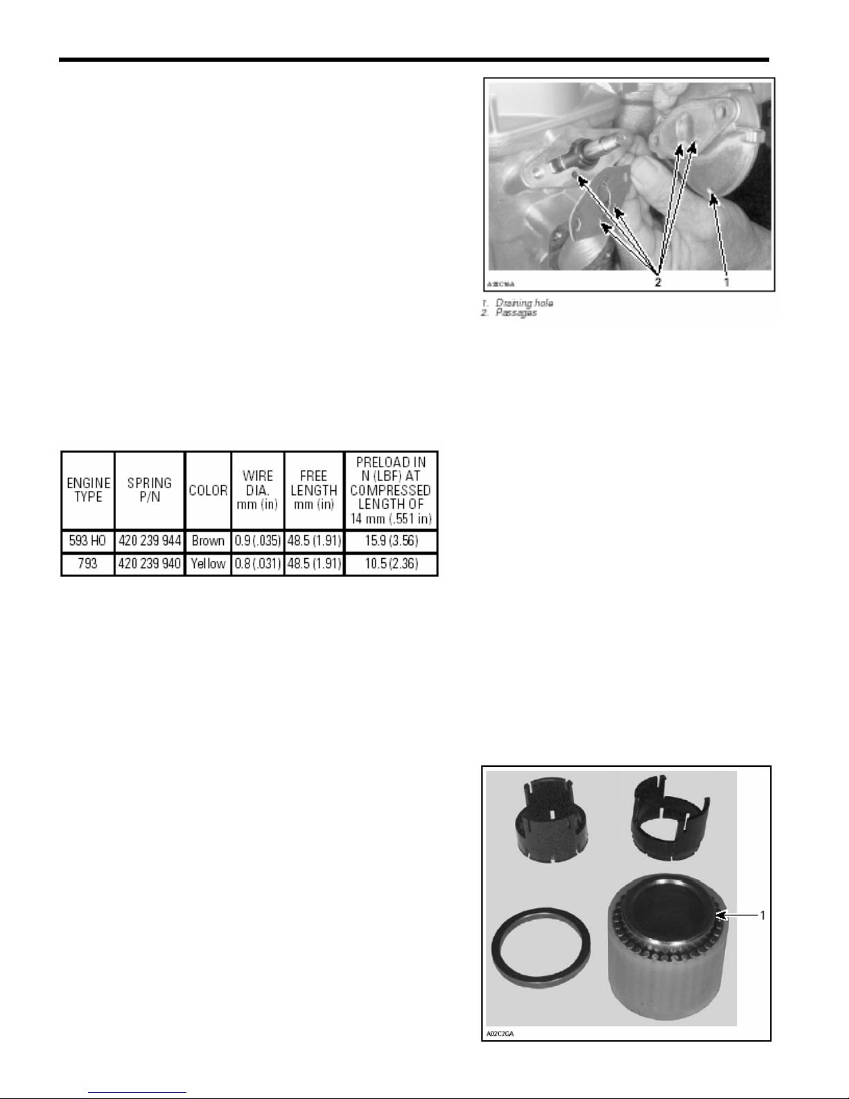
Check valve rod housing and cylinder for clogged
passages.
●
NOTICE:
Oil dripping from draining hole (No. 1) indicates a loose spring or
damaged bellows.
8, Bellows
Check for cracked, dried or perforated bellows.
12, Spring
ASSEMBLY
RAVE System
Install RAVE valve (noting which is the top side when it was
removed) Tighten red cap no. 15 screw to bottom.
2,13, Cylinder and Piston
Before inserting piston in cylinder, lubricate the
cylinder with new injection oil or equivalent.
24,21,2, Cylinder Head Cover, Cylinder Head and Cylinder
Make sure parts sealing surfaces are flat. Refer to LEAK TEST
AND ENGINE DIMENSION MEASUREMENT at the end of this
chapter and look for CYLINDER HEAD WARPAGE.
When installing a new cageless bearing, replace half plastic
cages with sleeve.
●
NOTICE:
All 593 HO engine cageless bearings have 28 needles.

o Oil needle bearing with injection oil.
o Grease thrust washers and install them on each end of
needles. The grease will help to hold them in place.
o Insert cageless bearing into connecting rod.
o Heat piston with a 100 W lamp or a heat gun before
piston installation to make the insertion of the pin much
easier.
▼ CAUTION
Piston temperature must not exceed 46°C (115°F). Never
use direct flame to heat the piston and never freeze the
pin.
At assembly, place the pistons over the connecting rods with the
letters “AUS” (over an arrow on the piston dome) facing towards
the exhaust port.
1. Exhaust
Install shouldered sleeve.
Install piston pin puller and turn handle until piston pin is correctly
positioned in piston.
ENGINE (CYLINDERS / HEAD / BASE) 7 - 13

ENGINE (CYLINDERS / HEAD / BASE) 7 - 14
All Models
▼ CAUTION
Always install new circlips. To minimize the effect of
acceleration forces on circlip, install each circlip so the
circlip break is at 6 o’clock as illustrated. Use appropriate
piston circlip installer.
Use circlip installer (P/N 529 035 686) to install new mono-hook
circlips no. 16. Insert circlip into support so that, when installed
in piston groove, the tab faces upward.
With round end of pusher, position circlip perpendicularly to the
support axis.
With the other end of the pusher, push circlip into the
support groove.

Using a plastic hammer, tap the pusher to put the circlip in place.
Make sure to install new circlips with the tab toward the top as
per the following photos.
▼ CAUTION
Always install new mono-hook circlips. If circlip
installation fails at the first attempt, always retry with a
new one because, on a second attempt, the circlip will
lose its normal retaining capabilities.
▼ CAUTION
Circlips must not move freely after installation; if so,
replace them. Clean cylinders and crankcase mating
surfaces with Loctite Chisel (P/N 413708500). Coat
crankcase mating surface with Loctite 518 (P/N
293800038). Choose the right gasket thickness according
to combustion chamber volume. Refer to LEAK TEST
AND ENGINE DIMENSION MEASUREMENT. Install it on
the crankcase. Coat gasket with Loctite 518.
ENGINE (CYLINDERS / HEAD / BASE) 7 - 15
▼ CAUTION
Always install a gasket of the proper thickness. Failure to
do so may cause detonation and severe engine damage.
Before inserting piston in cylinder, lubricate the cylinder
with new injection oil or equivalent. Install cylinders. Do
not tighten. Install new rubber ring and round O-rings on
each cylinder.
●
NOTICE:
Carefully clean screws before reinstallation, specifically under
screw head.
Install exhaust manifold with gaskets. Do not tighten yet.
Torque cylinder screws in a crisscross sequence as per the
following table:

ENGINE (CYLINDERS / HEAD / BASE) 7 - 16
At assembly, torque cylinder head screws to 29 N-m
(21 Ibf-ft) in the illustrated sequence at right.
Tighten exhaust manifold bolts to 23 N-m (17 lbf-ft) in a crisscross sequence.
Apply Loctite 243 (P/N 293 800 060) on screws threads.
Install outlet socket and tighten screws to 12 N-m (106 Ibf-in).
Note position of longer screw.
1. Longer screw
35, Reed Valve
All Engines
Blades have a curved shape. Install with their curve facing
reed block.
With blade stopper no. 37 removed, check reed valve for
proper tightness. There must not be any play between blade
and valve body when exerting a finger pressure on blade at
blade stopper location.
In case of a play, turn blade upside down and recheck. If there
is still a play, replace blade and/or valve body.
Check distance from blade stopper outer edge and
distance from center of reed valve block.
TYPICAL
A. 18.7 - 0, + 0.75 mm (.736 - 0, + .030 in)
Bend blade stopper as required to obtain the proper distance.
Blade stoppers may slightly interfere with cylinder during
installation. Adjusted distance will be reduced automatically
upon installation.

BOTTOM END
●
NOTICE:
The engine must be removed from the chassis to carry out the
following operations. See Chapter 4 – Engine Removal for
details.
CLEANING
o Discard all gaskets and O-rings.
o Clean all metal components in a non-ferrous metal
cleaner. Use gasket remover (P/N 413708500)
accordingly.
o Remove old paste gasket material from crankcase
mating surfaces with gasket remover (P/N 413708500)
▼ CAUTION
Never use a sharp object to scrape away old sealant as
score marks incurred are harmful to crankcase sealing.
DISASSEMBLY
General
To remove drive pulley, refer to Chapter 8 – Primary
Transmission System. To remove magneto, refer to CDI
SYSTEM in Chapter 14 – Electrical System.
2,3,5,7 Crankshaft Bearings
To remove bearings from crankshaft, use a protective
cap and special puller, as illustrated.
1. PTO side
2. MAG side
This includes the following parts:
P/N Description
420940755 M16x1.5x150 Screw
420840681 M8x40 Screw (4)
420841201 M8x70 Screw (4)
Crankshaft protector PTO All engines
420876552
420876557
420977490
420977475 Half Ring (2) For 72mm OD brgs.
420276025 Half Ring (2) For 62mm OD brgs.
420977480 Puller Ring
420977494
420977479 Half Ring (2) For 80mm OD brgs.
420876330 Half Ring (2) For 52mm OD brgs.
except 247
Crankshaft protector MAG All engines
except 247
Puller Ring (Use with half rings
420977475 or 420276025)
Puller Ring (Use with half rings
420977479)
ENGINE (CYLINDERS / HEAD / BASE) 7 - 17

ENGINE (CYLINDERS / HEAD / BASE) 7 - 18
INSPECTION
NOTE: Refer to LEAK TEST AND ENGINE DIMENSIONS
MEASUREMENT (End of this chapter)
ASSEMBLY
Coat lip of all seals with Petamo grease (P/N 420 899 271).
5, Crankshaft Bearing
Smear anti-seize lubricant (P/N 413 701 000) on part of
crankshaft where bearing fits.
Prior to installation, place bearings into an oil container filled with
injection oil previously heated to 75°C (167°F). This will expand
the bearing and ease installation.
Some bearings must be lubricated with Isoflex grease (P/N 293
550 021).
▼ CAUTION
Use only the recommended Isoflex grease. Make sure not
to push Isoflex grease between outside bearing race and
half crankcase. Use a sharp object to scrape away old
sealant as score marks incurred are harmful to crankcase
sealing.
●
NOTICE:
The 50 g tube corresponds to 50 cc of grease.
Put 50 to 55 mL of grease in a syringe.
▼ CAUTION
Do not exceed the recommended amount of grease.
Fill inner side of PTO side bearing with Isoflex grease (about 10
mL) as shown at right.
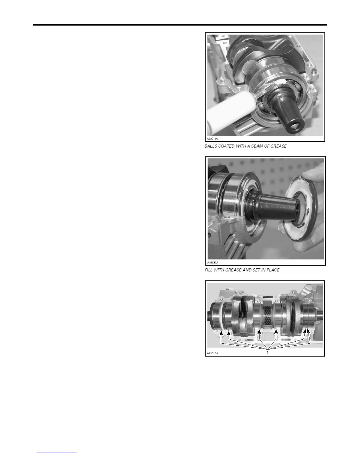
With the syringe, fill the outer ball bearing and inner side of outer
seal with 40 to 45 mL of Isoflex grease as shown at right.
Apply 6 mL of grease to MAG side outer bearing.
●
NOTICE:
If replaced with new bearing, do not apply grease as new
bearings come with grease already applied.
At crankshaft installation, position drive pins as illustrated.
1. Position pins
Pour 50 mL (2 U.S. oz) of injection oil in the pan under central
gear to lubricate pump gearing as per photo.
1. Oil bath
Crankcase Assembly
IMPORTANT: The total assembly sequence, including sealing
compound spreading, screwing and torquing of bolts according to
the proper sequence, must be performed within 10 minutes. Do
not wait between each bolt torquing. All bolts must be
torqued in a row.
ENGINE (CYLINDERS / HEAD / BASE) 7 - 19
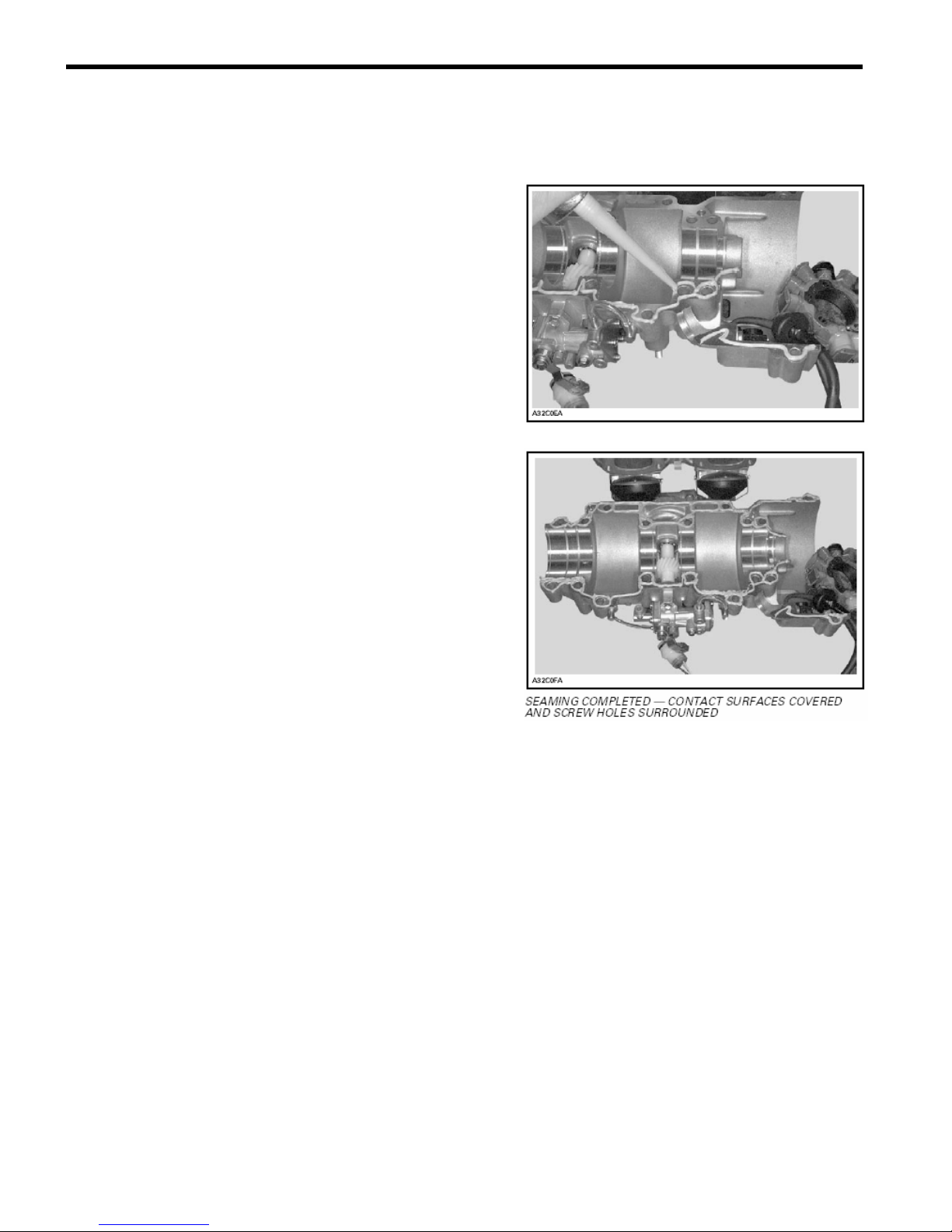
ENGINE (CYLINDERS / HEAD / BASE) 7 - 20
Before screwing together both parts of crankcase, seal it with
sealing compound (P/N 420 297 906). Make sure surfaces are
perfectly clean and degreased before applying sealing
compound.
Spread a seam of 1.2 mm (1/16 in) maximum in diameter on the
surface of lower crankcase half.
As far as possible, sealing compound must be applied in one run
to avoid any risks of leakage through the crankcase.

Screw all crankcase bolts in place in the following sequence and
to the appropriate torque; this must be done in two steps,
torquing: first, screw bolts up to 60% of the final torque (18 N-m
(13.5 lbf-ft) for most of the bolts), then, tighten to the required
torque (i.e. 29 N-m (21 lbf-ft)).
A. Torque bolts 1 through 16 to 29 N-m (21 lbf-ft)
B. Torque bolts 17 through 21 to 9 N-m (80 lbf-in)
BREAK-IN
After rebuilding an engine, always observe a break-in
period as described in Chapter 1 – General Instructions.
ENGINE (CYLINDERS / HEAD / BASE) 7 - 21

ENGINE (CYLINDERS / HEAD / BASE) 7 - 22
LEAK TEST AND ENGINE MEASUREMENT
LEAK TEST
The following gives verification procedures for
593 HO engines.
PREPARATION
1. Remove tuned pipe.
2. Install plug over exhaust manifold.
3. Remove carburetors.
4. Insert plugs in intake rubber boots. Tighten with
existing clamps.
5. Using a hose pincher (P/N 295 000 076), block impulse
hose.
6. Install air pump on exhaust plug.
●
NOTICE:
If necessary, lubricate air pump piston with mild soap.
▼ CAUTION
Using hydrocarbon lubricant (such as engine oil) will
damage rubber seal of pump piston.
7. Activate pump and pressurize engine to 34 kPa
(5 PSI). Do not exceed this pressure.
8. Engine must stand this pressure during 3 minutes.
– If pressure drops before 3 minutes, check tester kit by spraying
a soapy solution on pump cylinder, all plugs and fittings.
– If tester kit is leaking, bubbles will indicate where leak comes
from.
– If tester kit is not leaking, check engine as per the following
procedure.
PROCEDURE
●
NOTICE:
A flow chart has been prepared as a visual reference. Page 7-25
and 7-26 of this chapter.
Using the flow chart and the following text, pressurize area to be
tested and spray soapy solution at the indicated location.
– If there is a leak at the tested location, it is recommended to
continue testing the next item before overhauling the engine.
There is a possibility of more than one leak.

– If there is no leak at the tested location, continue pumping to
maintain pressure and continue with the next item until the leak is
found.
Engine
Check the following:
1. All jointed surfaces and screw/stud threads of engine:
– spark plug base, insulator
– cylinder head
– RAVE valve bellows, piston and housing
– cylinder
– crankcase halves (joint)
– oil injection pump mounting flange (O-ring)
– coolant pump housing
– bleed screws/plugs.
2. Remove cooling system cap.
Check for air bubbles in antifreeze. It indicates defective cylinder
head O-ring or cylinder base gasket.
3. Remove drive pulley then check crankshaft outer seal.
4. Remove rewind starter and magneto system then check
crankshaft outer seal.
5. Check pump shaft gear oil reservoir.
Pump Shaft Oil Gear Reservoir
Install air pump on adapter and pressurize as shown at right. If
pressure drops, it indicates a defective crankshaft inner seal.
CRANKSHAFT INSTALLED IN UPPER HALF CRANKCASE
1. Crankshaft inner seal on PTO side
2. Crankshaft inner seal on MAG side
ENGINE (CYLINDERS / HEAD / BASE) 7 - 23

ENGINE (CYLINDERS / HEAD / BASE) 7 - 24
1. Check weep hole below coolant pump housing with soapy
water.
1. Weep hole
If there is a leak, it indicates that a pump shaft is defective (oil
seal beside coolant ceramic seal).
2. Leaks can be also on the oil pump side, which is blocked off on
the Snow Hawk 600HO. Check this mounting area and the two
mounting bolts for leaks.
3. If leak still persists, it indicates a defective casting somewhere
in the engine.
Disassemble engine and carefully check for defects in castings.
Pay attention to tapped holes which may go through engine
sealed area and thus lead to leakage.
FINALIZING REASSEMBLY
After reassembling engine, always recheck for leakage.

ENGINE (CYLINDERS / HEAD / BASE) 7 - 25
CHECK FOR OIL LEAKS AROUND OIL
PUMP BLOCK-OFF PLATE
OIL LEAKING FROM AROUND
EDGES OF BLOCK-OFF PLATE?
REPLACE GASKET

ENGINE (CYLINDERS / HEAD / BASE) 7 - 26
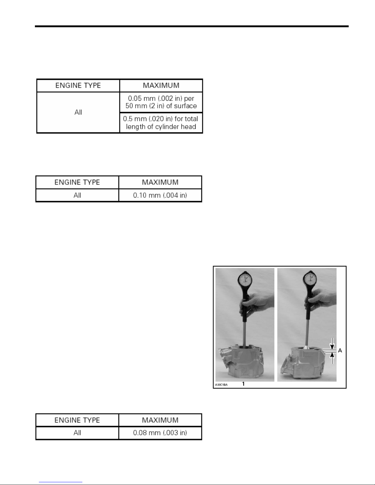
ENGINE DIMENSION MEASUREMENT
This section covers the 593HO engine type.
CYLINDER HEAD WARPAGE
ENGINE (CYLINDERS / HEAD / BASE) 7 - 27
Check gasketed surface of the cylinder head with a straightedge
and a feeler gauge.
CYLINDER TAPER
Compare cylinder diameter 16 mm (5/8 in) from top of cylinder to
just below its intake port area. If the difference exceeds the
specified dimension the cylinder should be rebored and honed or
should be replaced. Nikasil cylinder can be honed using diamond
hone but cannot be rebored.
●
NOTICE:
Be sure to restore the chamfer around all cylinder sleeve port
openings.
1. Below the intake port
A. 16 mm (5/8 in) from top
CYLINDER OUT OF ROUND

ENGINE (CYLINDERS / HEAD / BASE) 7 - 28
Measuring 16 mm (5/8 in) from top of cylinder with a cylinder
gauge, check if the cylinder out of round is more than the
specified dimension. If larger, cylinder should be rebored and
honed or should be replaced. Nikasil cylinder can be honed using
diamond hone but cannot be rebored.
●
NOTICE:
Be sure to restore the chamfer around all cylinder sleeve port
openings.
1. Piston pin position
2. Measures to be compared
A. 16 mm (5/8 in)
COMBUSTION CHAMBER VOLUME MEASUREMENT
The combustion chamber volume is the region in the cylinder
head above the piston at Top Dead Center. It is measured with
the cylinder head installed on the engine.
1. Combustion chamber
●
NOTICE:
When checking the combustion chamber volume, engine must be
cold, piston must be free of carbon deposits and cylinder head
must be leveled.
1. Remove both spark plugs and bring one piston
to Top Dead Center a using a TDC gauge.
1. Bring piston to TDC

2. Remove cylinder head.
3. Seal piston ring gap with a small amount of grease.
4. Reinstall cylinder head.
5. Obtain a graduated burette (capacity 0 - 50 cc) and fill with an
equal part (50/50) of gasoline and injection oil.
1. Graduated burette (0 - 50 cc)
6. Open burette valve to fill its tip. Add liquid in burette until level
reaches 0 cc.
7. Inject the burette content through the spark plug hole until
liquid touches the top spark plug hole.
. Top of spark plug hole
ENGINE (CYLINDERS / HEAD / BASE) 7 - 29
●
NOTICE:
The liquid level in cylinder must not drop for a few seconds after
filling. If so, there is a leak between piston and cylinder. The
recorded volume would be false. Reseal the piston ring gap and
follow the instruction provided above.
8. Let burette stand upward for about 10 minutes, until liquid level
is stabilized.
9. Read the burette scale to obtain the quantity
of liquid injected in the combustion chamber.
●
NOTICE:
When the combustion chamber is filled to top of spark plug hole,
it includes an amount of 2.25cc corresponding to the spark plug
well.
10. Repeat the procedure for the other cylinder.

ENGINE (CYLINDERS / HEAD / BASE) 7 - 30
11. Install a thicker or thinner cylinder/crankcase gasket (refer to
Parts Catalogs) in order to obtain the specified combustion
chamber volume or the nearest.
USED PISTON MEASUREMENT
Note the measurement on the piston dome.
1. Piston dome
2. Piston measurement
Using a micrometer, measure piston skirt at 15 mm (.590 in)
perpendicularly (90°) to piston pin.
1. Measuring perpendicularly (90°) to piston pin axis
A. 15 mm (.590 in)
The measured dimension must not be less than 0.15 mm (.006
in) of the one scribed on piston dome. Otherwise, install a new
piston.
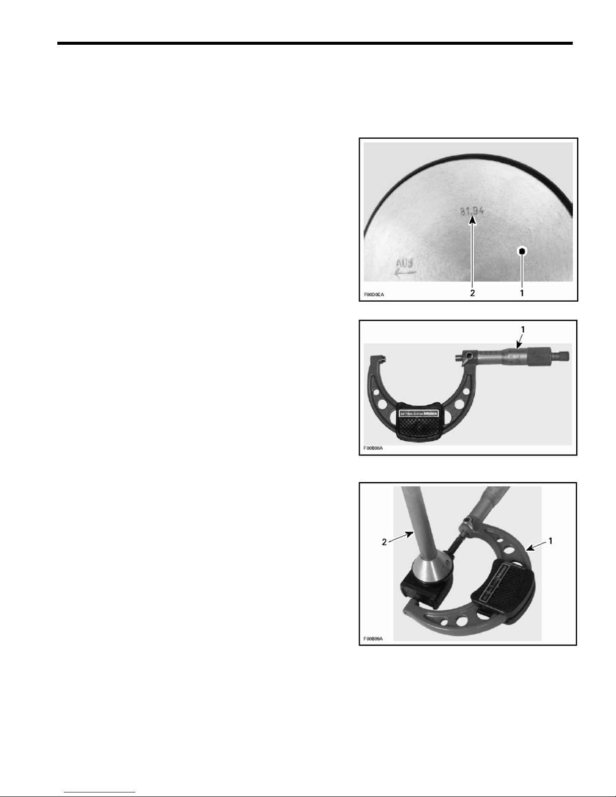
CYLINDER/PISTON CLEARANCE
Used and New Pistons
IMPORTANT: Make sure used piston is not worn more than
specified. See USED PISTON MEASUREMENT above.
Take the measurement on the piston dome.
1. Piston dome
2. Piston measurement
Adjust and lock a micrometer to the specified value
on the piston dome.
1. Micrometer set to the piston dimension
With the micrometer set to the piston dimension, adjust a cylinder
bore gauge to the micrometer dimension and set the indicator to
0.
1. Use the micrometer to set the cylinder bore gauge
2. Dial bore gauge
ENGINE (CYLINDERS / HEAD / BASE) 7 - 31

ENGINE (CYLINDERS / HEAD / BASE) 7 - 32
1. Indicator set to 0 (zero)
IMPORTANT: Always remove cylinders from crankcase before
measuring.
Position the dial bore gauge at 16 mm (5/8 in) below cylinder top
edge.
1. Measuring perpendicularly (90°) to piston pin axis
A. 16 mm (5/8 in)
Read the measurement on the cylinder bore gauge. The result is
the exact piston/cylinder wall clearance. If clearance exceeds
specified tolerance, replace cylinder.
●
NOTICE:
Make sure the cylinder bore gauge indicator is set exactly at the
same position as with the micrometer, otherwise the reading will
be false.
IMPORTANT: The total piston/cylinder clearance (actual cylinder
diameter minus actual piston skirt diameter) should be within 0.30
mm (.012 in).

RING/PISTON GROOVE CLEARANCE
Using a feeler gauge check clearance between
rectangular ring and groove. Replace piston if clearance
exceeds specified tolerance. Refer to Chapter 15 – Dimensions
and Tolerances..
RING END GAP
Position ring half-way between transfer ports and intake port.
●
NOTICE:
In order to correctly position the ring in the cylinder, use piston
as a pusher.
Using a feeler gauge, check ring end gap. Replace ring if gap
exceeds specified tolerance. Refer to Chapter 15 – Dimensions
and Tolerances.
1. Transfer port
2. Intake port
CRANKSHAFT DEFLECTION
Crankshaft deflection is measured with a dial indicator.
Measuring (in crankcase)
First, check deflection with crankshaft in crankcase. If deflection
exceeds the specified tolerance, recheck deflection using Vshaped blocks to determine the defective part(s). See below.
Measuring (on bench)
Once engine is disassembled, check crankshaft deflection on Vshaped blocks. If deflection exceeds the specified tolerance, it
can be worn bearings or a bent crankshaft. Remove crankshaft
bearings and check deflection again on V-shaped blocks
to determine the defective part(s). See measurement A in
following illustration.
1. Measure at mid point between the key and the first thread
A. 3 mm (1/8 in)
ENGINE (CYLINDERS / HEAD / BASE) 7 - 33

ENGINE (CYLINDERS / HEAD / BASE) 7 - 34
●
NOTICE:
Crankshaft deflection cannot be correctly measured between
centers of a lathe.
If the deflection exceeds the specified tolerance, crankshaft
should be repaired or replaced.
Using a feeler gauge, measure distance between thrust washer
and crankshaft counterweight. If the distance exceeds specified
tolerance, repair or replace the crankshaft.

CRANKSHAFT END-PLAY
End-play is not adjustable but it should be between 0.10 - 0.30
mm (.004 - .012 in).
CHECKING CRANKSHAFT ALIGNMENT
o Install a degree wheel (P/N 529 035 607) on crankshaft
end.
o Remove both spark plugs.
o Install a TDC gauge (P/N 414 104 700) in spark plug hole
on MAG side.
o Bring MAG piston to top dead center.
o Rotate degree wheel (not crankshaft) so that 360° mark
aligns with center of crankcase. Scribe a mark on
crankcase.
o Remove TDC gauge and install it on center cylinder.
o Bring PTO piston to top dead center. Degree wheel must
rotate with crankshaft.
Interval between cylinders must be 180° ± 0.5. Any other reading
indicates a misaligned (twisted) crankshaft.
ENGINE (CYLINDERS / HEAD / BASE) 7 - 35

PRIMARY TRANSMISSION SYSTEM 8-1
PRIMARY TRANSMISSION SYSTEM / PRIMARY CLUTCH
10 N-m (1 kg-m ,
7.4 lbf-ft, 125 lbf-in)
90 N-m (9.2 kg-m ,
66 lbf-ft, 797 lbf-in)

PRIMARY TRANSMISSION SYSTEM 8-2
A
y
Ref. P/N Qty Part Descriptions
1-14 0400-0152 1 Primary Clutch Assembly
Primary Transmission System / Primary Clutch
1 0405-0071 1Fixed sheave
2 0410-0022 1 Sliding sheave
3
4
5
6
7
8
9
10
11
12
13
14
15
16
0150-1014
0440-2018 1 Spring Compression Limiter
0151-1007 1 Spring
0440-0005 1 Spring Cover
420-2453-700 3 Lock Washer
0080-0021 3 Socket Head Screw
0130-3006 3 Slider Block
X-81-3 15 Mass (small)
0135-3001 3 Mass (large)
X-7 3 Threaded Cap
0130-0153 3
0115-3042 1 Plated Cover (D1)
0080-0162 1 Machined Washer
V16J1 1 Nut
1
Spring seat
rm Assembl
 Loading...