

SnowEx SP-9300X User Manual

Owner / Operator’s Manual
This Manual Must Be Read Before Operating The Equipment
Madison Heights, Michigan 48071
800-SALTERS
www.snowexproducts.com
© TrynEx International 2014
(REV C) F50718
SP-9300X
Serial No. Q2-100198 and higher
CUSTOMER COPY
1

Table of Contents
General Information ...................................................................................................................................................................................... 3
Introduction .................................................................................................................................................................................................. 4
Safety ........................................................................................................................................................................................................... 5
Warning Decal Positions ............................................................................................................................................................................. 6-7
Operating Instructions .............................................................................................................................................................................. 8-11
Wiring Instructions ...................................................................................................................................................................................... 12
Control Diagram ..................................................................................................................................................................................... 13-15
Electrical Components Diagrams ........................................................................................................................................................... 16-18
Mounting Instructions ................................................................................................................................................................................. 12
Troubleshooting .......................................................................................................................................................................................... 21
Warranty ..................................................................................................................................................................................................... 22
Key to Parts ................................................................................................................................................................................................ 23
Frame Assembly Parts Breakdown ......................................................................................................................................................... 24-25
Auger Drive Assembly Parts Breakdown ................................................................................................................................................. 26-27
Hopper Assembly Parts Breakdown ........................................................................................................................................................ 28-29
Auger Extension Assembly Parts Breakdown .......................................................................................................................................... 30-31
Spinner Drive Assembly Parts Breakdown .............................................................................................................................................. 32-33
Grease Fitting Extension Parts Breakdown .................................................................................................................................................. 34
Notes .......................................................................................................................................................................................................... 35
Have a Question or Need Assistance?
SnowEx Customer Care
(800) SALTERS
or (248) 586-3500
Monday through Friday 8:00 AM to 4:30 PM EST
Fax: (248) 691-8378
E-mail: customercare@trynexfactory.com
Website: www.turfexproducts.com
2 © TrynEx International 2014 (REV C) F50718

General Information
CONGRATULATIONS!
The spreader you have purchased is an example of snow and ice control technology at its nest! Your spreader’s self-contained design is a
trademark of all SnowEx products. Here’s why…
SIMPLICITY: Fewer moving parts manufactured of higher quality means minimal maintenance for your SnowEx spreader.
RELIABILITY: High impact linear low density polyethylene hopper. State-of-the-art electronic dual variable speed control, custom engineered
powder coated frame, maximum torque 12-Volt motor coupled to a custom engineered transmission; found only on SnowEx products.
VERSATILITY: Multi-use capabilities allows spreading of a variety of materials for snow and ice control.
WARRANTY: Best in the industry, hands down! 2 years standard and now 5 year extended (optional).
The benets you are about to recognize are that of time, money and effort.
We welcome you to the world of SnowEx Performance.
Registration
Record the following in this manual for quick reference.
Model Number .................................................................................................................................................................................................
Serial Number ..................................................................................................................................................................................................
Control Board Serial Number ............................................................................................................................................................................
Handheld Control Pendant Serial Number .........................................................................................................................................................
Date of Purchase .............................................................................................................................................................................................
Dealer Where Purchased ..................................................................................................................................................................................
When ordering parts, the above information is necessary. This will help to
ensure that you receive the correct parts.
At the right is a diagram of the ID tag. This tag is located on the frame.
Please register you warranty with all the necessary information to validate
it. This will give us a record so that any safety or service information can be
communicated to you.
Model No. SP-9300X
Model No. Q2-100198
Madison Heights, MI 48071 U.S.A.
1-800-725-8377 trynexfactory.com
Manuf. 2013
3© TrynEx International 2014 (REV C) F50718
Introduction
This manual has been designed for your help. It will assist you and instruct you on the proper set-up, installation and use of this product.
Refer to the table of contents for an outline of this manual.
We require that you read and understand the contents of this manual completely (especially all safety information) before attempting any
procedure contained in this manual. Extra copies of Owner/Operator’s Manuals can be purchased at your SnowEx dealer.
THIS SIGN SHOULD ALERT YOU:
The Society of Automotive Engineers has adopted this Safety Alert Symbol to pinpoint characteristics that,
if not carefully followed, can create a safety hazard. When you see this symbol in this manual or on the
machine itself, be alert! Your personal safety and the safety of others is involved.
Dened below are the Safety Alert Messages and how they will appear in this manual:
RED
Information that, if not carefully followed, can cause death.
ORANGE
Information that, if not carefully followed, can cause serious personal injury or death.
YELLOW
Information that, if not carefully followed, can cause minor injury or damage to equipment.
4 © TrynEx International 2014 (REV C) F50718

Safety
Before attempting any procedure in this book, these safety instructions must be read and understood by all workers who have any part in the
preparation or use of this equipment.
For your safety, warning and information decals have been placed on this product to remind the operator of safety precautions. If anything
happens to mark or destroy the decals, please request new ones from SnowEx.
Never exceed the Gross Vehicle Weight Rating of vehicle. Failure to do so may limit a vehicles handling
characteristics.
Never attempt to take a unit off a truck with material in it.
Always keep hands, feet, and clothing away from power driven parts.
Unit must be pinned and locked into position before operating vehicle.
Always shut off vehicle and power source before attempting to attach or detach or service unit. Be sure
vehicle/power source is properly braked and chocked.
Remember most accidents are preventable and caused by human error. Exercising of care and precautions
must be observed to prevent the possibility of injury to operator or others.
Never operate equipment when under the inuence of alcohol, drugs, or medications that might alter your
judgement and/or reaction time.
Before working with the spreader, secure all loose tting clothing and unrestrained hair.
Always wear safety glasses with side shields when servicing spreader. Failure to do this could result in serious injury to the eyes.
Never allow children to operated or climb on equipment.
Always check areas to be spread to be sure no hazardous conditions or substances are in the area.
Always inspect unit for defects: broken, worn or bent parts, weakened areas on spreader.
Remember it is the owner’s responsibility to communicate information on safe usage and proper maintenance of all equipment.
Always make sure personnel are clear of areas of danger when using equipment.
Never weld or grind on equipment without having a re extinguisher available.
Inspect the unit periodically for defects. Parts that are broken, missing or worn out must be replaced immediately. The unit or any part of it can not be altered without prior written permission from the manufacturer.
Always inspect pins and latches whenever attaching or detaching spreader, and before operation of
spreader.
Never exceed 45 MPH when loaded spreader is attached to vehicle. Braking distances may be increased and
handling characteristics may be impaired at speeds above 45 MPH.
Never use wet materials or materials with foreign debris with any spreader. The unit is designed to handle
dry, clean, free owing material.
Never leave material in hopper for long periods of time. Be aware that all ice melters are hygroscopic and
will attract atmospheric moisture and harden up.
5© TrynEx International 2014 (REV C) F50718
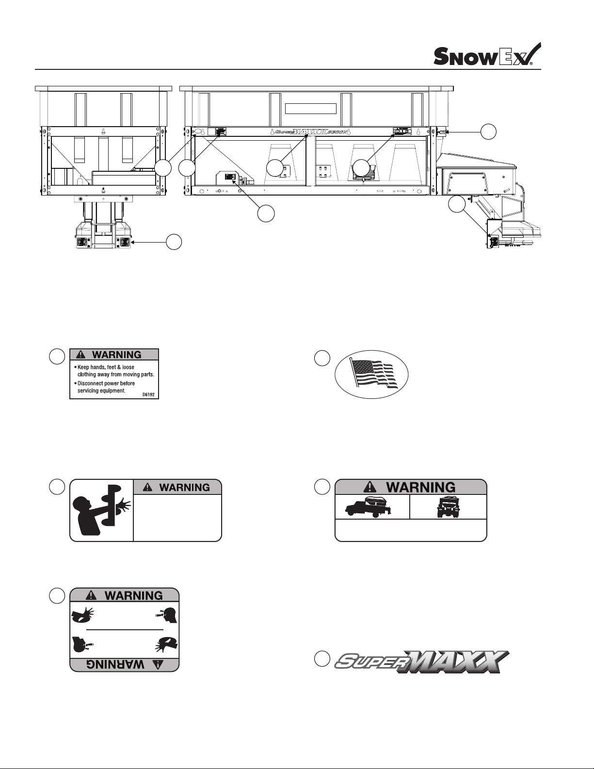
Warning Decal Positions
6
1
D6192
2 3 7
1
5
4
5
2
MADE IN THE USA
D6243
3
D6335
ROTATING AUGER CAN CAUSE
SERIOUS INJURY OR DEATH
• Keep arms, hands, and loose clothing away from auger.
• Shut off control and unplug spreader before servicing.
D6335
4
• DO NOT EXCEED GVWR OF VEHICLE
• DO NOT OVERLOAD SPREADER
• LOAD SPREADER EVENLY
D6546
D6546
5
ROTATING PARTS CAN CAUSE
SERIOUS INJURY OR DEATH
• ALWAYS DISCONNECT POWER
WHEN NOT IN USE
WHEN NOT IN USE
• ALWAYS DISCONNECT POWER
SERIOUS INJURY OR DEATH
ROTATING PARTS CAN CAUSE
6
F50645
6 © TrynEx International 2014 (REV C) F50718
F50553
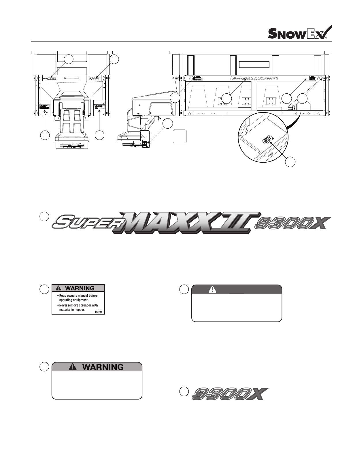
Warning Decal Positions
10
6
11
9
7
3
2
5
9
8
7
F51037
8
D6194
10
• Read Owner’s Manual for Installation Instructions.
• Secure spreader to truck with ratchet straps.
• Anchor spreader securely to truck body with bolt kit provided to prevent
slipping or sliding.
• Routinely check straps and handware to make sure they are secure.
D6548
D6548
9
• DO NOT REMOVE SPREADER WITH MATERIAL IN HOPPER
• FASTEN SPREADER DOWN WITH APPROVED RATCHET STRAPS
AND BOLT KIT
• REAR FRAME LOCATOR BARS MUST BE IN PLACE BEFORE
OPERATING VEHICLE
DANGER
D6547
11
F50554
D6547
7© TrynEx International 2014 (REV C) F50718

Operating Instructions
USING CONTROL PENDANT
1. Push On/Off button.
2. Press the Start/Stop button. Auger and Spinner will begin to turn, spreading material.
3. Use dials on Control Pendant to adjust Material Distribution Shaft speed. This will change the spread rate at constant vehicle speed.
4. Press Start/Stop to stop spreading. Turn off Spreader by pushing the On/Off button.
LOADING THE SPREADER
Warning: Do not overload vehicle.
Use chart below to calculate weight of material. Weights of materials are an average for dry materials.
MATERIAL WEIGHT PER CUBIC FOOT
Rock Salt 80-90 lbs.
Sand/Salt Mix 95-120 lbs.
Warning: Never leave material in hopper for long periods of time as salt is hygroscopic and will attract atmospheric moisture and
harden up.
When spreading Sand/Salt Mix, a 1:1 ratio is recommended to prevent the material from freezing.
SPREADING TIPS
For a heavier pass:
Decrease vehicle speed
Increase Auger speed
For a lighter pass:
Increase vehicle speed
Decrease Auger speed
For a wider pass:
Increase spinner speed
Spread ice melters with the storm to prevent unmanageable levels of ice.
Never exceed 10 miles per hour when spreading.
Calculate spread pattern when near vegetation and other vehicles.
Never operate spreader near pedestrians.
WARNING PROTECTION
• If audible beeping occurs, read display to identify problem.
• If display reads “OL” (overload) or “OH” (overheat), shut the controller down and carefully clear jammed auger.
• If display reads “E1” this means there is a dead short in the system. Do not use until problem is corrected.
• If the display reads “E0” this means the motor is not getting any power. Check all connections.
• If the display reads “LB” the vehicle battery is extremely low (possibly caused by a poor or corroded connection) and could damage the
system.
• If there are any problems while operating the spreader, refer to Troubleshooting Guide.
8 © TrynEx International 2014 (REV C) F50718

Operating Instructions
AUTO-REVERSE “AR” FUNCTION
• If your controller displays “OL” this could indicate a jammed auger.
• To engage the Auto-Reverse “AR” Function:
1. Push the On/Off button to turn controller OFF for 3 seconds
2. Push the On/Off button again to turn power ON. When the machine starts back up, the AR sequence will automatically start and
the auger will reverse for several rotations to clear the jam.
• After a pause of several moments, the auger will automatically return to correct rotation. If the jam is still not cleared, the controller will
again display OL.
• You may repeat Steps 1 and 2 for a second and third time.
• If after the third try the controller displays OL, you must extract the material that is causing the problem.
• Follow all warning directions when clearing jams.
MAINTENANCE
Use dielectric grease on all electrical connections to prevent corrosion at the beginning and end of the season and each time power plugs are
disconnected.
Wash unit after each use to prevent material build-up and corrosion.
Paint or oil all bare metal surfaces at the end of the season.
Apply small amount of light oil to latches as needed.
After rst use, tighten all nuts and bolts on spreader and mount.
Grease bearings after every 20 hour’s use.
Vibrator is not designed for continuous duty. Allow motor to cool between long cycle times.
Do not modify vehicle or spreader wiring harness. Doing so will void product warranty.
When servicing is necessary, perform it in a protected area Do not use power tools in rain or snow because
of danger of electrical shock or injury. Keep area well lighted. Use proper tools. Keep the area of service
clean to help avoid accidents.
Never remove spreader with material in hopper.
Disconnect electricity to spreader before servicing.
When replacing parts use only SnowEx parts. Failure to do so will void warranty.
The controller is a solid state electronic unit and is not serviceable. Any attempt to service will void warranty.
There are no serviceable parts in the motor/transmission assembly. Any attempt to service will void warranty.
When pressure washing motor enclosure area, stay at least 36’’ away from motor enclosures.
Store control in cool dry place during the off season.
Spinner motor is not designed for continuous duty. Allow motor to cool between long cycle times.
Vibrator is not designed for continuous duty. Allow motor to cool between long cycle times.
Do not modify vehicle or spreader wiring harness. Doing so will void product warranty.
9© TrynEx International 2014 (REV C) F50718
Operating Instructions
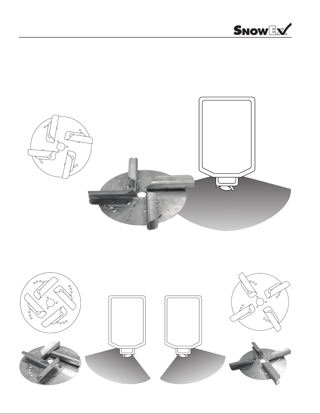
Adjustable Spinner
Your spreader is equipped with an adjustable spinner to assist you in more precise material application. The Spinner plate gives the operator
control of whether the material spreads to the right, left or is centered. Before operating the spreader, spread some material in a clear area
where you can easily observe the spread pattern and how it changes with n adjustment. Use the instructions below as a guide to get the
spread pattern you desire.
When the ns are in their center adjustment position, the spread pattern will be mostly centered.
When looking down at the spinner, moving the ns clockwise will
adjust the spread pattern toward the left side of the spreader.
10 © TrynEx International 2014 (REV C) F50718
When looking down at the spinner, moving the ns counter-
clockwise will adjust the spread pattern toward the right side of the
spreader.
Operating Instructions
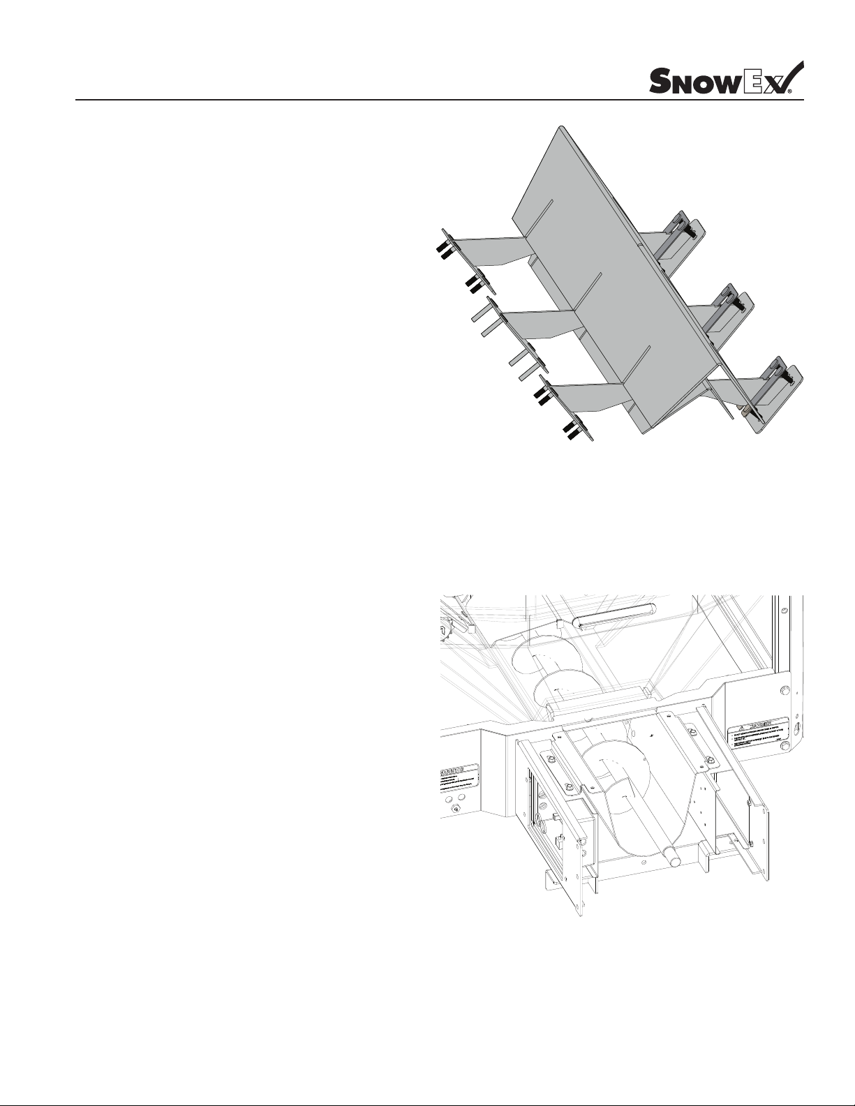
INVERTED-V
The SuperMAXX 9300 uses an “Inverted-V” Bafe design over
the auger area. This bafe reduces the load on the auger.The
Inverted-V should not be removed unless servicing the unit.
The Secondary Salt Bafe can be removed for spreading Sand/
Salt Mix.
Warning: Always disconnect power source before attempt-
ing to remove material bafe.
AUGER DISCHARGE TROUGH
The SuperMAXX 9300 uses an Auger Discharge Trough to reduce
material leakage. It must not be removed unless servicing the
unit.
Warning: Always disconnect power source before attempting to remove auger discharge tube.
11© TrynEx International 2014 (REV C) F50718
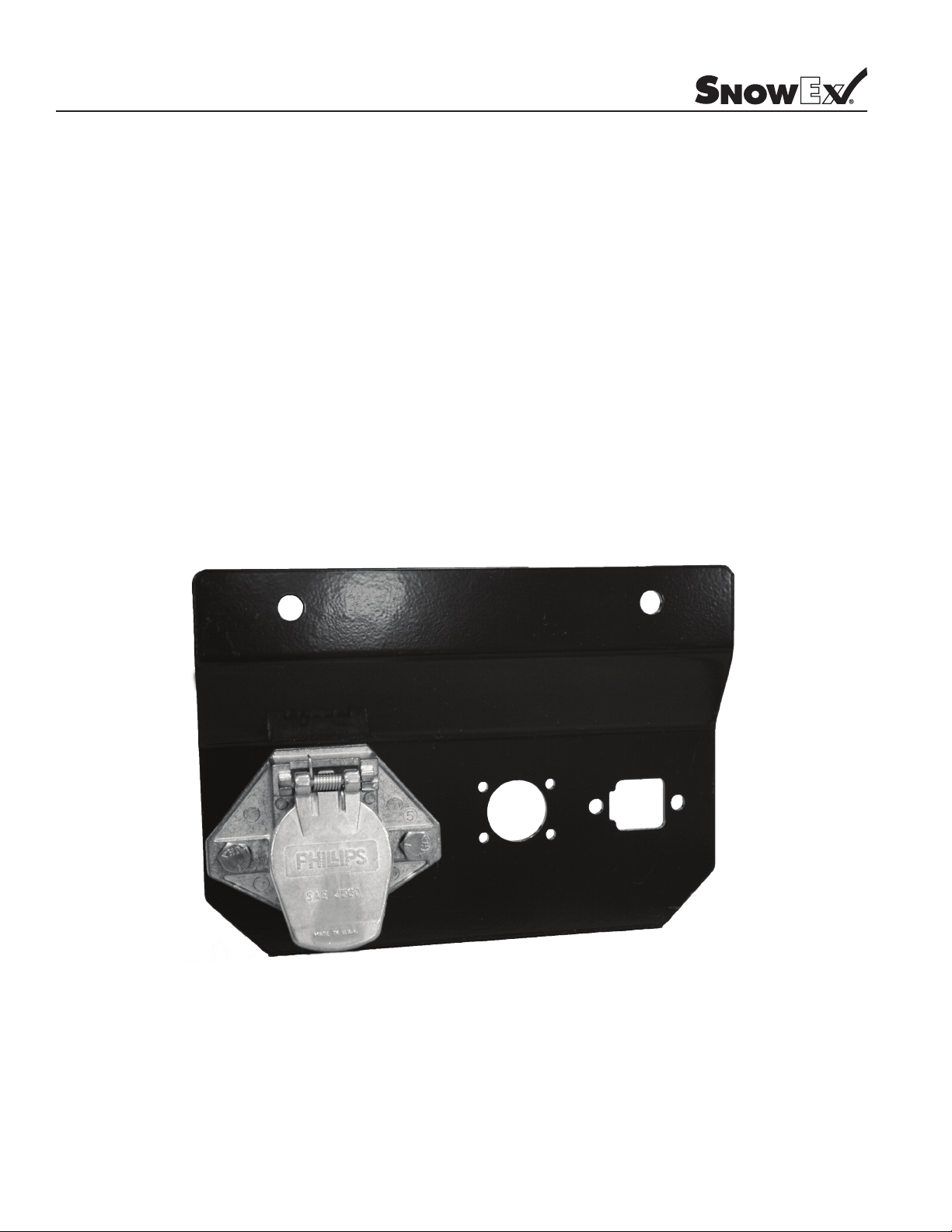
Wiring Instructions
1. Mount rear plug bracket on back of vehicle using supplied bolts. Locate toward center of bumper as it will reduce the amount of debris
that gets onto the plug.
2. Mount vehicle harness plugs to bumper bracket that was just installed. [The Power Harness Plug will need to be removed and mounted to
the bracket, then re-connected to the wires.] Apply dielectric grease to plugs.
3. Route wires from back to front using ty-wraps or clamps (not supplied). Do not secure to brake lines, fuel lines, or near exhaust, engine or
moving parts. Use the heavy-duty ty-wraps along frame and the lighter duty ty-wraps everywhere else.
4. Drill a 7/8” hole in the rewall near steering column. Be sure to check for wires and components in the way (both sides of rewall) before
drilling the hole.
5. Run the Data Cable into cab. Zip-tie wire under dash so it does not get in the way of brake or accelerator pedal. Leave enough of the Data
Cable outside of the dash so operator can hold control pendant in hand. Install the Pendant Mounting Base and Bracket. Stick hook/loop
fastener to the Pendant and Pendant Base.
6. Splice the short wire on the Vehicle Data Cable into the Third Brake Light Circuit of the vehicle.
7. Route power wires over to battery. Install circuit breaker and connect to battery.
View of Vehicle Power Harness Plug Attached
to Bumper Bracket.
12 © TrynEx International 2014 (REV C) F50718
 Loading...