


This Manual Must Be Read Before Operating The Equipment
Owner / Operator’s Manual
FOR MODELS
SP-7550 Serial # L1-144130 and higher
Madison Heights, Michigan 48071
800-725-8377
www.snowexproducts.com
© Trynex International 2011 (REV 001)
Customer Copy
1

Table of Contents
General Information ...................................................................................................................................................................................... 3
Introduction ................................................................................................................................................................................................. 4
Safety .......................................................................................................................................................................................................... 5
Warning Decal Positions..............................................................................................................................................................................6-7
Operating the Spreader ...............................................................................................................................................................................8-9
Drive Enclosure Installation Instructions ..................................................................................................................................................... 10
Spreader Maintenance ............................................................................................................................................................................... 11
General Wiring Instructions ........................................................................................................................................................................ 12
Control and Harness Diagram ............................................................................................................................................................... 13-17
Mounting Instructions .............................................................................................................................................................................18-19
Troubleshooting .................................................................................................................................................................................... 20-21
Warranty .................................................................................................................................................................................................... 22
Spreader Views
Model # SP-7550 ......................................................................................................................................................................... 23
Frame Assembly Parts Breakdown
Model # SP-7550 .................................................................................................................................................................... 24-25
Auger Drive Assembly Parts Breakdown
Model # SP-7550 .................................................................................................................................................................... 26-27
Hopper Assembly Parts Breakdown
Model # SP-7550 .................................................................................................................................................................... 28-29
Drive Assembly Parts Breakdown
Model # SP-7550 .................................................................................................................................................................... 30-31
Notes .............................................................................................................................................................................................. 32-33
Have a question or need assistance?
SnowEx Customer Care
(800) 725-8377
or (248) 586-3500
Monday through Friday 8:00 AM to 4:30 PM EST
Fax: (248) 691-8378
E-Mail: customercare@trynexfactory.com
Website: www.snowexproducts.com
2
© Trynex International 2011 (REV 001)

General Information
CONGRATULATIONS!
The spreader you have purchased is an example of snow and ice control technology at its nest! Your spreader’s self-contained design is a
trademark of all SnowEx products. Here’s why…
SIMPLICITY: Fewer moving parts manufactured of higher quality means minimal maintenance for your SnowEx spreader.
RELIABILITY: High impact linear low density polyethelyne hopper. State-of-the-art electronic dual variable speed control, custom engineered
powder coated frame, maximum torque 12-volt motor coupled to a custom engineered transmission; found only on SnowEx products.
VERSATILITY: Multi-use capabilities allows spreading of a variety of materials for snow and ice control.
WARRANTY: Best in the industry, hands down! 2 years standard and now 5 year extended (optional).
The benets you are about to recognize are that of time, money and effort.
We welcome you to the world of SnowEx Performance.
Registration
Record the following information in this manual for quick reference.
Spreader Model Number
Spreader Serial Number Controller Serial Number
Date of Purchase
Dealer Where Purchased
When ordering Parts, the above information is necessary. This will help to see that you
receive the correct parts.
At the right is a diagram of the ID tag. This tag on the spreader is located on the frame.
Madison Heights, MI 48071
Please ll out the warranty card with all the necessary information to validate it.
This will also give us a record so that any safety or service information can be
communicated to you.
U.S.A.
1-800-725-8377
www.trynexfactory.com
Model No.
SP-7550
L1-000000
Serial No.
© Trynex International 2011 (REV 001)
3
Introduction
This manual has been designed for your help. It will assist you and instruct you on the proper set-up, installation and use of this spreader.
Refer to the table of contents for an outline of this manual.
We require that you read and understand the contents of this manual completely (especially all safety information) before attempting any
procedure contained herein.
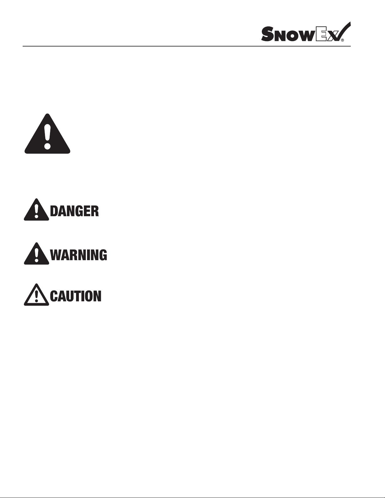
THIS SIGN SHOULD ALERT YOU:
The Society of Automotive Engineers has adopted this SAFETY ALERT SYMBOL to pinpoint characteristics
that, if NOT carefully followed, can create a safety hazard. When you see this symbol in this manual or on the
machine itself, BE ALERT! Your personal safety and the safety of others is involved.
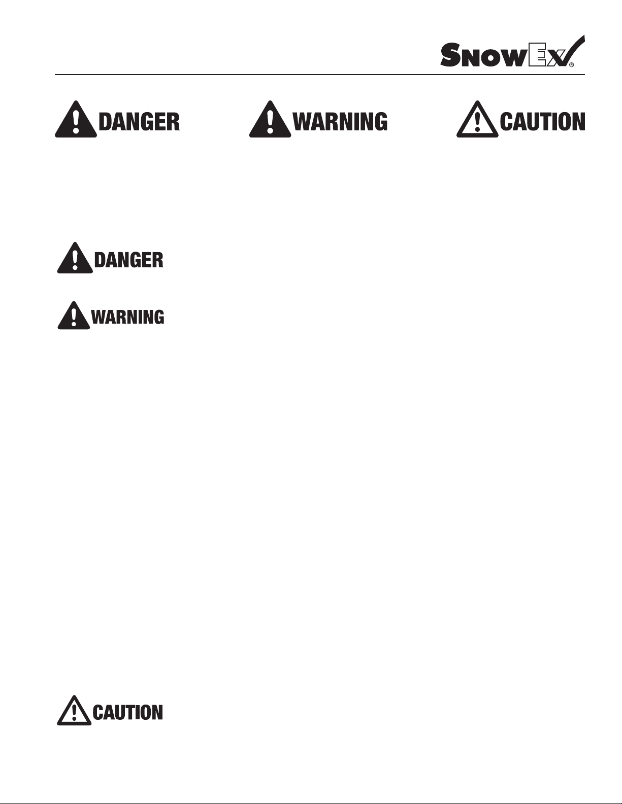
Dened below are the SAFETY ALERT messages and how they will appear in this manual:
(RED)
Information that, if not carefully followed,
can cause death!
(ORANGE)
Information that, if not carefully followed,
can cause serious personal injury or death!
(YELLOW)
Information that, if not carefully followed,
can cause minor injury or damage to equipment
4
© Trynex International 2011 (REV 001)
Safety
Before attempting any procedure in this book, these safety instructions must be read and understood by all workers who have any part in the
preparation or use of this equipment.
For your safety warning and information decals have been placed on this product to remind the operator of safety precautions . If anything
happens to mark or destroy the decals, please request new ones from SnowEx.
Never exceed the Gross Vehicle Weight Rating of vehicle. Failure to do so may limit a vehicles handling
characteristics.
Never attempt to take a unit off a truck with material in it.
Always keep hands, feet, and clothing away from power driven parts.
Unit must be pinned and locked into position before operating vehicle.
Always shut off vehicle and power source before attempting to attach or detach or service unit Be sure
vehicle/power source is properly braked or chocked.
Remember, most accidents are preventable and caused by human error. Exercising of care and precautions
must be observed to prevent the possibility of injury to operator or others!
Never operate equipment when under the inuence of alcohol, drugs, or medications that might alter your
judgment and/or reaction time.
Before working with the spreader, secure all loose tting clothing and unrestrained hair.
Always wear safety glasses with side shields when servicing spreader. Failure to do this could result in
serious injury to the eyes.
Never allow children to operate or climb on equipment.
Always check areas to be spread to be sure no hazardous conditions or substances are in the area.
Always inspect unit for defects: broken, worn or bent parts, weakened areas on spreader.
Remember it is the owner’s responsibility to communicate information on safe usage and proper
maintenance of all equipment.
Always make sure personnel are clear of areas of danger when using equipment.
Never weld or grind on equipment without having a re extinguisher available.
Inspect the unit periodically for defects. Parts that are broken, missing or worn out must be replaced
immediately. The unit or any part of it can not be altered without prior written permission from the
manufacturer.
Always inspect pins and latches whenever attaching or detaching spreader, and before operation of spreader.
Never exceed 45 m.p.h. when loaded spreader is attached to vehicle. Braking distances may be increased
and handling characteristics may be impaired at speeds above 45 m.p.h.
Never use wet materials or materials with foreign debris with any of these spreaders. These units are
designed to handle dry, clean, free owing material.
Never leave material in hopper for long periods of time. Be aware that all ice melters are hygroscopic and will
attract atmospheric moisture and harden up.
© Trynex International 2011 (REV 001)
5
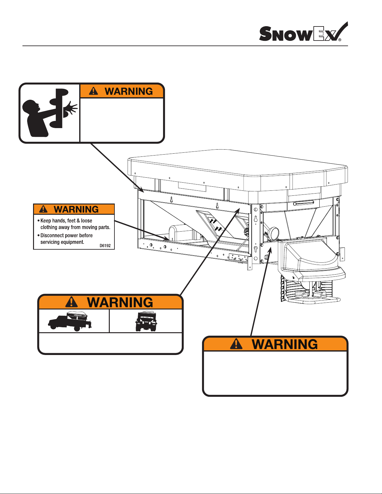
Warning Decal Positions
Model # SP-7550
ROTATING AUGER CAN CAUSE
SERIOUS INJURY OR DEATH
• Keep arms, hands, and loose clothing
away from auger.
• Shut off control and unplug spreader
before servicing.
D6335
• DO NOT EXCEED GVWR OF VEHICLE
• DO NOT OVERLOAD SPREADER
• LOAD SPREADER EVENLY
6
D6546
• Read Owner’s Manual for Installation Instructions.
• Secure spreader to truck with ratchet straps.
• Anchor spreader securely to truck body with bolt kit provided to prevent
slipping or sliding.
• Routinely check straps and handware to make sure they are secure.
D6548
© Trynex International 2011 (REV 001)
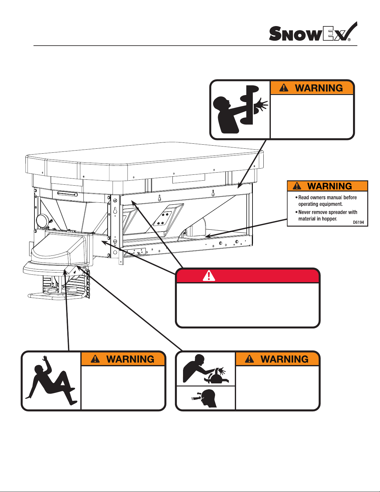
Warning Decal Positions
Model # SP-7550
ROTATING AUGER CAN CAUSE
SERIOUS INJURY OR DEATH
• Keep arms, hands, and loose clothing
away from auger.
• Shut off control and unplug spreader
before servicing.
D6335
NO STEP
• Slippery Surface When Wet.
• May Cause Severe Injury
D6545
DANGER
• DO NOT REMOVE SPREADER WITH MATERIAL IN HOPPER
• FASTEN SPREADER DOWN WITH APPROVED RATCHET STRAPS
AND BOLT KIT
• REAR FRAME LOCATOR BARS MUST BE IN PLACE BEFORE
OPERATING VEHICLE
ROTATING PARTS AND FLYING OBJECTS
CAN CAUSE INJURY OR DEATH
• Keep hands, arms, feet and loose clothing away
• Shut off power ans stop engine before servicing
• Read owners manual before operating.
• Keep bystanders at least 60 ft away.
D6547
D6544
© Trynex International 2011 (REV 001)
7

Operating the Spreader
Model # SP-7550
SPREADER LOADING
WARNING – Do not overload vehicle. Use chart below to calculate weight of material. Weights of material are an average for dry
materials.
Material Weight Per Cubic Ft.
Rock Salt 80-90 lbs.
Sand/Salt Mix 95-120 lbs.
• Warning – Never leave material in hopper for long periods of time as salt is hygroscopic and will attract atmospheric moisture and harden up.
When spreading sand mix, a 1:1 ratio for Sand/Salt mix is recommended to prevent the material from freezing.
SPREADER OPERATION
• The Dual Variable Speed Controller has dual nger-tip dials for maximum performance, digital system status with warning protection and built-
in Vibrator Switch.
• To start, press power switch on controller and spreader will accelerate to speed set on spinner and auger dials.
• To stop, press power on controller to off position.
• Speed of Auger and Spinner may be adjusted separately to get desired ow and spread distance
• The Vibrator Switch is needed for dense material or to increase the ow to the Auger. This eliminates bridging of material in hopper.
• A Material Bafe has been installed in your spreader to stop ne material from free owing. If using dense or damp material, or if more ow is
desired, remove Material Bafe. However, it is recommended that the Material Bafe remain in place if using bulk salt.
• It is important that the Inverted Vee not be removed except when servicing.
• If there are any problems while operating the spreader, refer to Troubleshooting Guide.
SPREADING TIPS
• Spread ice melters with the storm to prevent unmanageable levels of ice.
• Never exceed 10 m.p.h. when spreading.
• For a wider pass, increase spinner speed.
• For a heavier pass, drive slower or increase auger speed.
• Never operate spreader near pedestrians.
• Calculate spread pattern when near vegetation.
WARNING PROTECTION
• If audible beeping occurs, read display to identify problem. If display reads “OL” (overload) or “OH” (overheat), shut controller down and
carefully clear jammed auger. If display reads “E1“ this means there is a dead short in system. Do not use until problem is corrected. If display
reads “E0” this means that the motor is not getting any power. Check all connections. If display reads “LB” the vehicle battery is extremely
low (possibly caused by a poor or corroded connection) and could damage the system.
• If there are any problems while operating the spreader, refer to Troubleshooting Guide.
8
© Trynex International 2011 (REV 001)
Operating the Spreader (continued)
Model # SP-7550
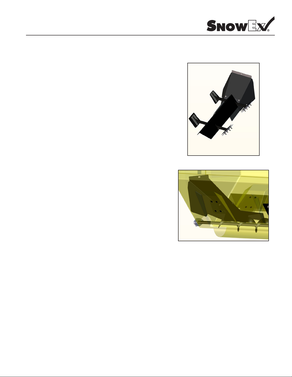
DISCHARGE BAFFLE and INVERTED-V INSTRUCTIONS
• The 7550 uses an Inverted-v design over the auger area. This
inverted-v (D5510) is used to reduce load to the auger drive train. It
must not be removed unless servicing the unit.
• WARNING: Always disconnect power source before attempting to
remove material bafe.
• The 7550 uses a discharge bafe (D5517) to reduce material
leakage. It must not be removed unless servicing the unit.
• BAFFLE EXTENSION INSTRUCTIONS
• The Bafe Extension (D-5503) is intended to be used with very dry
products that free-ow with little effort. The bafe is designed to
keep these types of materials from leaking out.
• If you plan on using damp/wet materials, you should remove this
bafe by removing the self-drilling screws.
D5517
D5510
D5503
• If you are using a sand/salt mixture, remove bafe extension.
© Trynex International 2011 (REV 001)
9
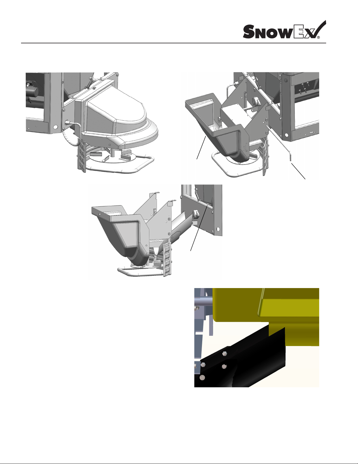
Drive Enclosure Installation Instructions
Model # SP-7550
Step1: Lift latch up
Step 2: Swing hood
open
Step 3: Pull main pin
Important
When installing drive unit on spreader make sure the material
chute clips under the trough of the hopper.
Step 4: Lift drive assembly off pins
10
© Trynex International 2011 (REV 001)

Spreader Maintenance
Model # SP-7550
• WARNING – When servicing is necessary, perform it in a protected area Do not use power tools in rain or snow because of danger of electrical
shock or injury. Keep area well lighted. Use proper tools. Keep the area of service clean to help avoid accidents.
• WARNING: Never remove spreader with material in hopper.
• WARNING: Disconnect electricity to spreader before servicing.
• CAUTION: – When replacing parts use only original manufacturer”s parts. Failure to do so will void warranty.
• CAUTION: – The controller is a solid state electronic unit and is not serviceable. Any attempt to service will void warranty.
• CAUTION: - There are no serviceable parts in the motor/transmission assembly. Any attempt to service will void warranty.
• CAUTION: - Spinner motor is not designed for continuous duty. Allow motor to cool between long cycle times.
• CAUTION: – When pressure washing motor enclosure area, stay at least 36’’ away from motor enclosures.
• ATTENTION: Store control in cool dry place during the off season.
• Use dielectric grease on all electrical connections to prevent corrosion at the beginning and end of the season and each time power plugs are
disconnected.
• Wash unit after each use to prevent material build-up and corrosion.
• Paint or oil all bare metal surfaces at the end of the season.
• Apply small amount of light oil to latches as needed.
• If motor cover is removed for any reason, use silicone sealant to ensure weather proong of enclosure.
• After rst use, tighten all nuts and bolts on spreader and mount.
• Grease bearings after every 20 hour’s use.
• CAUTION – Vibrator is not designed for continuous duty. Allow motor to cool between long cycle times.
• CAUTION – Do not modify vehicle or spreader wiring harness. Doing so will void product warranty.
© Trynex International 2011 (REV 001)
11

General Wiring Instructions
Model # SP-7550
Step 1: Take harness assembly and route from the rear of the vehicle to the front. Route harness along frame and attach to frame hole and
frame supports. It is not recommended to attach to fuel or brake lines for obvious reasons. Do not route close to exhaust system or
engine, even though Snowex uses high temperature wiring. It still could melt under extreme heat and short the spreader electrical
system, as well as the vehicle electrical system.
Step 2: Mount rear plug on bumper using supplied bolts, locate towards the center of the bumper to reduce the amount of debris the tires
will throw to the rear. Important: Apply a small amount of dielectric grease to the plug. Also try to mount so plug faces upward to
help keep plugs tightly sealed.
Step 3: Secure harness from the rear to the front using heavy duty ty-wraps or frame clips along the frame and lighter duty ty-wraps
everywhere else.
Step 4: Layout harness portion that connects to the battery along the re wall and fender well. Do not connect power leads to battery yet.
Drill a 3/4” hole in the re wall, or use existing access hole, for the control portion of the harness and route connector and harness
through hole. Be sure to check the area on the other side of the re wall to make sure you are not drilling into the vehicle harness
or a control module. Generally you can drill on either side of the steering wheel for a good location.
Step 4A: The power harness from control box to battery will need to be routed from the inside of the cab to the battery – this results from
the large high amperage connector. Route leads with lugs to battery — do not connect power at this time.
Step 5: Connect harness to the back of the controller and mount to a suitable location. NOTE: You may want to contact customer before
mounting controller as some prefer not to have holes drilled into the dashboard. Ty-wrap loose controller harness and move to the
engine compartment. Do not mount close to any heater vents.
Step 6: Connect power leads to the battery: Red + Positive, Black – Negative, always connect to the primary battery if using a dual battery
system. Secure loose loom to any other large or medium vehicle harness with medium duty ty-wraps, this will secure wiring
harness.
Step 7: Push the ON/OFF button on the controller to check for power ; when that has been conrmed turn power OFF. The electrical portion
of the installation is complete.
12
© Trynex International 2011 (REV 001)

Control and Harness Diagram
Model # SP-7550
5
7
9
IMPORTANT: In the off season remove control
2
and put in a cool dry place. The interior summer
temperatures could damage circuit board and
6
1
void warranty.
See CHMSL page 15
4
IMPORTANT: Do Not modify harness length. Any modications
will void warranty.
Special Notes:
1) All external connections must have dielectric grease.
2) Read lead labels before attaching to power source or ground.
3) No other devices may be spliced into wiring harness.
4) Any repairs to wiring harness must be done with heat shrink butt
connectors.
12
10
11
3
8
Key Part No. Description Qty
1 D5524 Spreader Harness | 87-1/4” 1
2 D5525 Spreader Control | SP-7550 1
3 D6118 Dust Cover | Standard 1
4 D6170 Connector Adapter | 6” Anderson 1
5 D6237 Power Switch | 5 Terminal 1
6 D6322 Vehicle Harness | 311” 1
7 D6341 Control Power Cable | 156” Pro 1
8 D6343 Dust Cover | Pro 2
9 D6354 Vibrator Switch | 3 Terminal Red 1
10 D6784 Utility Work Light 1
11 D6785 Spreader Auxiliary Harness | 56” 1
12 D6786 Vehicle Auxiliary Harness | 310” 1
© Trynex International 2011 (REV 001)
13

Harness Diagram
Model # SP-7550
D6322 Vehicle Harness
End View
White
10 GA
Spinner+
Black
10 GA
Spinner -
Blue
12 GA
Vibrator -
Red
Red
10 GA
Auger+
Green
10 GA
Auger -
Black
Orange
10 GA
Vibrator -
Spinner+
10 GA White
Auger+
10 GA Red
Vibrator+
12 GA Orange
Mold Cap
Spinner10 GA Black
Auger10 GA Green
Vibrator12 GA Blue
D6341 Control Power Cable
3/8” Terminal w/Heat Shrink
Black
Red
124” Tubing
Hot
Circuit
Front View
Red to
Positive +
Grd
Circuit
Black to
Negative -
14
© Trynex International 2011 (REV 001)

Harness Diagram
Model # SP-7550
D5524 Spreader Harness
VIBRATOR
PLUG
58"
5"
AUGER
SPINNER PLUG
LOAD
VIEW
RED
B
A
BLACK
BLACK
RED
D5525 Controller
87 1/4"
47"
Vibrator
Black Negative (-)
Vibrator
Red Positive (+)
VIBRATOR + RED
AUGER + RED
SPINNER + RED
BLACK - VIBRATOR
BLACK - AUGER
BLACK - SPINNER
LOAD VIEW
Black
Negative (-)
Red
Positive (+)
© Trynex International 2011 (REV 001)
Spinner
Black Negative (-)
Auger
Black Negative (-)
Auger
Red Positive (+)
Spinner
Red Positive (+)
IMPORTANT: In the off season remove control
and put in a cool dry place. The interior summer
temperatures could damage circuit board and
void warranty.
15

Harness Diagram
Model # SP-7550
D6785 Spreader Auxiliary Harness
28"
12"
BLUNT (2)
BURY LEADS
IN CONDUIT
BLACK-BLUNT
BLACK TO
MOLDED 2-WAY
BLACK TO PACKARD
LOAD VIEW
RED-BLUNT
RED TO
MOLDED 2-WAY
RED TO PACKARD
D6786 Vehicle Auxiliary Harness
27'
A-RED B-BLACK
B
A
28"
2-WAY CHMSL
3"
MOLD CAP
14"
BK
RD
BURY 12" WIRE IN CONDUIT
16
14"
310"
34"
12"
TAPE
27' BK
12" BK
4' BK
27' RD
4' RD
12" RD
© Trynex International 2011 (REV 001)

Harness Diagram
Model # SP-7550
D6514 Center High Mount Stop Lamp
Connect to Spreader Harness D6785
© Trynex International 2011 (REV 001)
17

Mounting System Diagrams
Model # SP-7550
Through Floor/Bed Mounting Bolts
1
2
3
Figure 2 : Frame Mounting Bolts
Key Part No. Description Qty
1 D4116 Bolt | 1/2”-13 X 1-1/2” 4
2 D4119 Washer | 1/2” Flat 4
3 D4120 Nut | 1/2”-13 Nylox 4
4 D4121 Bolt | 3/8”-16 X 1” 4
5 D4124 Nut | 3/8”-16 Nylox 4
6 D6536 Adjustable Stop Bracket | Right 1
7 D6537 Adjustable Stop Bracket | Left 1
8 D6856 V-Maxx Ratchet Straps 4
Rear Stop LT & RT
5 6 7
4
Figure 1 :
Side Strap On Each Side
8
Cross Front Straps
18
© Trynex International 2011 (REV 001)

Mounting Instructions
Model # SP-7550
Step 1: Remove tailgate from pickup bed.
Step 2: Load spreader on to truck bed and mount spinner assembly.
Step 3: Slide spreader forward until deector/chute assembly makes contact with vehicle. Then, slide spreader back approx. 1” to allow for
proper clearance.
Step 4: Install stop bars using supplied hole patterns (see Fig.2). To achieve the best position, you may need to drill additional holes in bracket in
order to properly position spreader.
Step 5: Now that the spreader is positioned front to back, you will now center it left to right. Looking at the inside front and corner of the lower
frame area, you will notice (4) holes in the bottom of the frame. Using a paint pen or similar marking device, mark hole locations.
Step 6: Before drilling holes, look beneath the approximate area where each hole will be located. Make sure there are no vehicle components
that will be in the path of the drill before doing this step. If there are interferences, you can relocate holes as needed making sure there
are at least two forward and two rearward of the front to back centerline.
Step 7: Install and tighten all (4) bolts.
Step 8: Install ratchet straps (see 7550 Mounting System: Strapping Techniques). It is very important for everyone’s safety this strapping method
be used as the standard mounting procedure. (Do not use ratchet straps exclusively.)
Step 9: Connect the spreader power cord to vehicle main power plug mounted at rear of vehicle (see Electrical Installation).
© Trynex International 2011 (REV 001)
19

Troubleshooting
Model # SP-7550
Spreader
Does Not Run
Controller Turns On
Beeps Shuts Off
Displays Error Code
OL Code
EO Code
Denition
Amp Draw
Too High
Denition
Open Circuit Between
Motor And Controller
Jammed Material
Bad Motor
Check With Test Kit
Bad Transmission
Check With Test Kit
Corrosion
Bad Controller
Check With Test Kit
Spreader Unplugged
Motor Power Cord
Disconnected
Inside Drive Assembly
Break In
Wiring Harness
Check With Test Kit
Clear Jam
Test 4 to 20 Amp Draw
No Load Good
20+ Amp Draw
No Load Bad
Test Turn Shaft
By Hand
Should Turn Freely
Replace All
Corroded
Connections
Plug In Spreader
Open Access Cover
And Plug Together
Replace Harness
Don´t Forget
Use Doelectric
Grease
On/Off Switch
Lights No Display
Nothing Happens
No Display
On/Off Will Not Light Up
LB Code
E1 Code
All Other Codes
Check Input Power
Check Power Source
To Controller
Denition
Bad Electrical
Connection
Low Battery
Less Than 12 Volt
Output
Denition
Dead Short
In Motor Circuit
Check Harness
For Spliced In
Accessory
Bad Controller
Check With Test Kit
Bad Controller
Check With Test KIt
Corrosion
Loose Connection
Load Test Battery
Replace Affected
Components
Bad Controller
Check With Test Kit
Replace All Corroded
Connections
Tighten Or Replace
Replace
Snowex Diagnostic Test Kit (STK-090) Is Available To Accurately Diagnose Any Issues With Snowex Spreaders.
Call Your Dealer For Details.
20
© Trynex International 2011 (REV 001)

Troubleshooting Material Flow
Model # SP-7550
Material Free Flows
Material Does Not Flow
Slow Material Flow
Check Bafe Length
Check Bafe Position
Material Obstruction
Auger Runs Backwards
Turn On Vibrator
Turn On Vibrator
Increase Auger Speed
Material Issue
18” Correct
Should Touch Hopper
On 3 Sides
Remove Obstruction
Run 12 Volt To Auger
Circuit On Spreader
Power Cord
Material Issue
Material Issue
Material Issue
Auger Runs Proper
Direction
Auger Runs
Backwards
Replace Vehicle
Harness
Check Connections
At Auger Motor For
Reverse Polarity
Polarity Correct
ReplaceSpreader
Harness
Snowex Diagnostic Test Kit (STK-090) Is Available To Accurately Diagnose Any Issues With Snowex Spreaders.
Call Your Dealer For Details.
© Trynex International 2011 (REV 001)
21

Warranty
Warranty
Limited Warranty
Snowex products are warranted for a period of two years from the date of purchase against
defects in material or workmanship under normal use and service, subject to limitations detailed
below. Warranty period of two years begins on the date of purchase by the original retail user.
The WARRANTY REGISTRATION CARD must be returned to the manufacturer for this warranty
to become eective. This warranty applies to the original retail purchaser only. This warranty does
not cover damages caused by improper installation, misuse, lack of proper maintenance, alterations
or repairs made by anyone other than authorized Snowex dealers or Snowex personnel. Due to the
corrosive properties of the materials dispensed by spreaders, Trynex does not warrant against
damage caused by corrosion. Warranty claims by the user must be made to the dealer from where
the product was purchased, unless otherwise authorized by Snowex. Snowex reserves the right to
determine if any part is defective and to repair or replace such parts as it elects. This warranty does
not cover shipping costs of defective
parts to or from the dealer.
LIMITATION OF LIABILITY
Neither Snowex, nor any company aliated with it, makes any warranties, representations for
promise as to the performance or quality other than what is herein contained. The liability of Snowex
to the purchaser for damages arising out of the manufacture, sale, delivery, use or resale of this
spreader shall be limited to and shall not exceed the costs of repair or replacement of defective
parts. Snowex shall not be liable for loss of use, inconvenience or any other incidental, indirect or
consequential damages, so the above limitations on incidental or consequential damages may not
apply to you.
NO DEALER HAS AUTHORITY TO MAKE ANY REPRESENTATION OR PROMISE ON BEHALF OF
SNOWEX, OR TO ALTER OR MODIFY THE TERMS OR LIMITATIONS OF THIS
WARRANTY IN ANY WAY.
22
© Trynex International 2011 (REV 001)

Spreader Views
Model # SP-7550
23
© Trynex International 2011 (REV 001)

Frame Assembly Parts Breakdown
8
9
8
4
1
8
2
5
6
3
7
Model # SP-7550
24
© Trynex International 2011 (REV 001)

Frame Assembly Parts Breakdown
ID #
Part #
Qty
1
D5504
1
2
D5505
2
3
D5506
1
4
D5507
2
ID #
Part #
Qty
5
D6158
2
6
D6468
2
7
D6514
1
8
D6528
14
ID #
Part #
Qty
9
D6529
2
Model # SP-7550
© Trynex International 2011 (REV 001)
25

Auger Drive Assembly Parts Breakdown
20
13
12
5
18
15
11
16
6
22
23
3
10
17
21
9
7
8
17
19414
1
2
Model # SP-7550
26
© Trynex International 2011 (REV 001)

Auger Drive Assembly Parts Breakdown
ID #
Part #
Qty
1
D4121
4
2
D4122
2
3
D5383
2
4
D5513
1
5
D5514
1
6
D5520
1
7
D5522
1
8
D5532
2
ID #
Part #
Qty
9
D5533
1
10
D5535
4
11
D6105
1
12
D6158
2
13
D6159
2
14
D6452
2
15
D6528
4
16
D6553
2
ID #
Part #
Qty
17
D6584
6
18
D6784
1
19
D6826
1
20
D6873
3
21
D7164
2
22
T20315
1
23
T30742
1
Model # SP-7550
© Trynex International 2011 (REV 001)
27

Hopper Assembly Parts Breakdown
14
6
15
4
15
11
2
3
5
13
1
7
8
3
13
9
12
10
Model # SP-7550
28
© Trynex International 2011 (REV 001)

Hopper Assembly Parts Breakdown
ID #
Part #
Qty
1
D5500
1
2
D5503
1
3
D5508
4
4
D5510
1
5
D5511
1
6
D5512
1
ID #
Part #
Qty
7
D5517
1
8
D6138
1
9
D6165
1
10
D6166
1
11
D6509
4
12
D6515
1
ID #
Part #
Qty
13
D6584
16
14
D6815
2
15
D6874
10
Model # SP-7550
© Trynex International 2011 (REV 001)
29

Drive Assembly Parts Breakdown
16
3
10
23
27
9
19
22
12
18
20
26721
4
14
6
10
25
24
5
11
8
1
2
15
17
28
13
Model # SP-7550
30
© Trynex International 2011 (REV 001)

Drive Assembly Parts Breakdown
ID #
Part #
Qty
1
D4135
1
2
D4289
7
3
D5502
1
4
D5518
1
5
D5536
2
6
D6107
1
7
D6131
4
8
D6132
4
9
D6133
1
10
D6138
6
ID #
Part #
Qty
11
D6162
1
12
D6172
2
13
D6198
1
14
D6232
1
15
D6467
6
16
D6524
8
17
D6553
1
18
D6563
1
19
D6781
1
20
D6819
1
ID #
Part #
Qty
21
D6820
1
22
D6823
1
23
D6824
1
24
D6827
1
25
D6832
1
26
D6833
1
27
D6854
3
28
F50438
2
Model # SP-7550
© Trynex International 2011 (REV 001)
31

Notes
32
© Trynex International 2011 (REV 001)

Notes
© Trynex International 2011 (REV 001)
33

Notes
34
© Trynex International 2011 (REV 001)

Notes
© Trynex International 2011 (REV 001)
35

 Loading...