

SnowEx SP-7000 Assembly Instructions

Assembly Instructions
Madison Heights, Michigan 48071
800-SALTERS
www.snowexproducts.com
© TrynEx International 2014
F51558 REV-A140905
SP-7000
Serial No. 140410300001SP-7000 and higher
CUSTOMER COPY
1
Introduction
These Installation Instructions have been designed to guide you while assembling and installing your SnowEx spreader. Follow these instructions with care to ensure performance and longevity.
Please read and understand the safety warnings associated with the assembly and installation of the spreader before beginning. In addition
the safety information in the these instructions, observe general safety guidelines to maintain your safety and the safety of those around you.
SAFETY ALERT DEFINITION
This Safety Alert Symbol is used to pinpoint characteristics that, if not carefully followed, can create a safety hazard. When you
see this symbol in this manual or on the machine itself, BE ALERT – your safety and the safety of others is involved.
An accident will occur, resulting in Serious Injury or Death if the instructions are not followed.
An accident may occur, resulting in Serious Injury, perhaps Death, if the instructions are not followed.
An accident may occur, resulting in Minor or Moderate Injury if the instructions are not followed.
Important Information; Property or Equipment Damage may result if not followed.
TORQUE CHART
Use this chart as a guide for tightening hardware.
Hand-tighten all fasteners until complete, then tighten to the recommended torque (unless
specied otherwise in these instructions).
TORQUE CHART FT-LB
Fastener Recommended
Torque (ft-lb)
1/4-20 6
5/16-18 13
3/8-16 23
7/16-14 35
1/2-13 55
9/16-12 80
5/8-11 110
3/4-10 200
7/8-9 320
1-8 480
2 © TrynEx International 2014 F51558 REV-A140905
Assembly Instructions
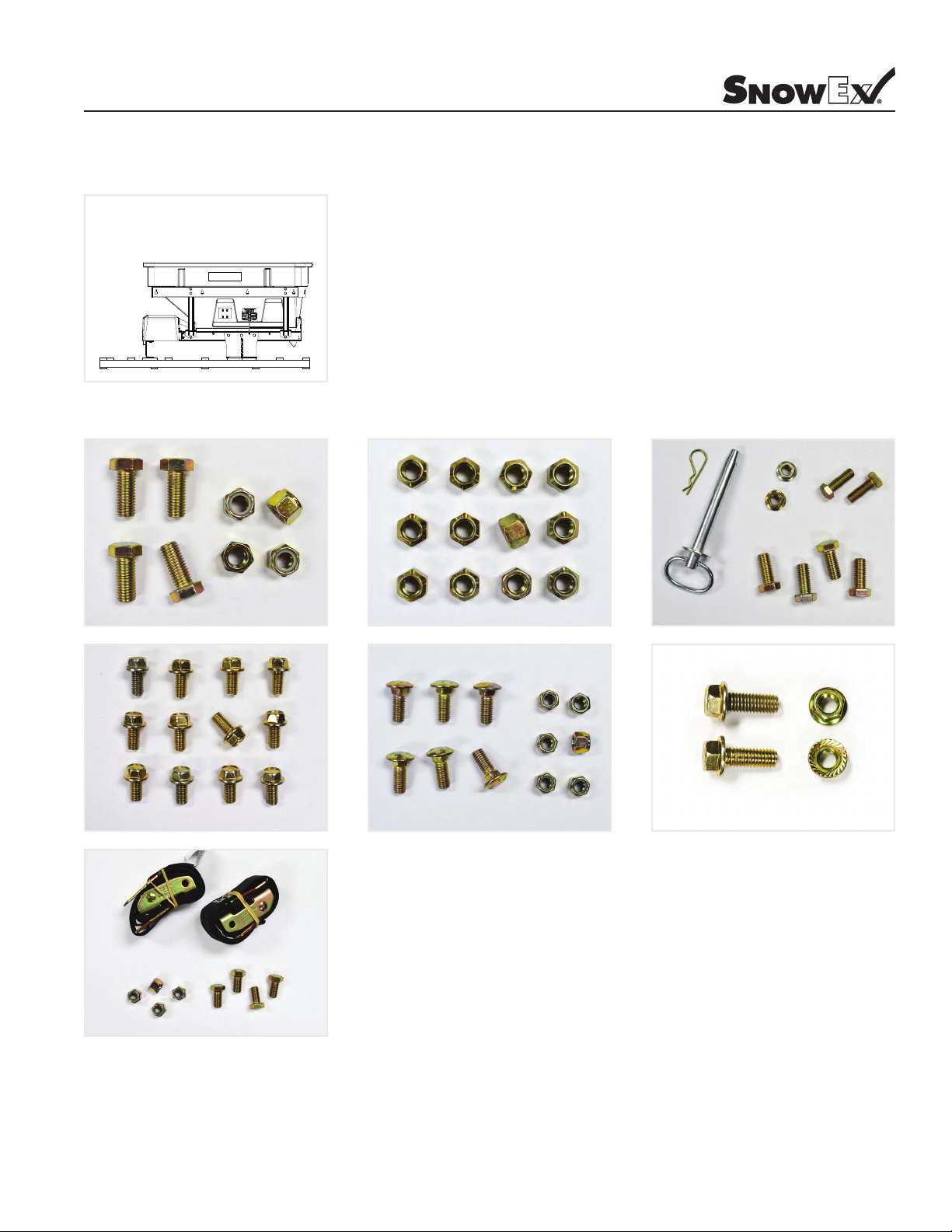
STEP 1
Unpack the spreader; remove the axle, tires, tongue, and spinner drive from the pallet, set aside so the main spreader assembly is alone on
the pallet.
STEP 2
Open the Spinner Drive Box. Open and locate the hardware kits.
AXLE WHEELS TONGUE
BATTERY
STEP 3
Remove the lag bolts holding the spreader to the pallet.
SPINNER DRIVEMUD FLAPFENDERS
3© TrynEx International 2014 F51558 REV-A140905
Assembly Instructions
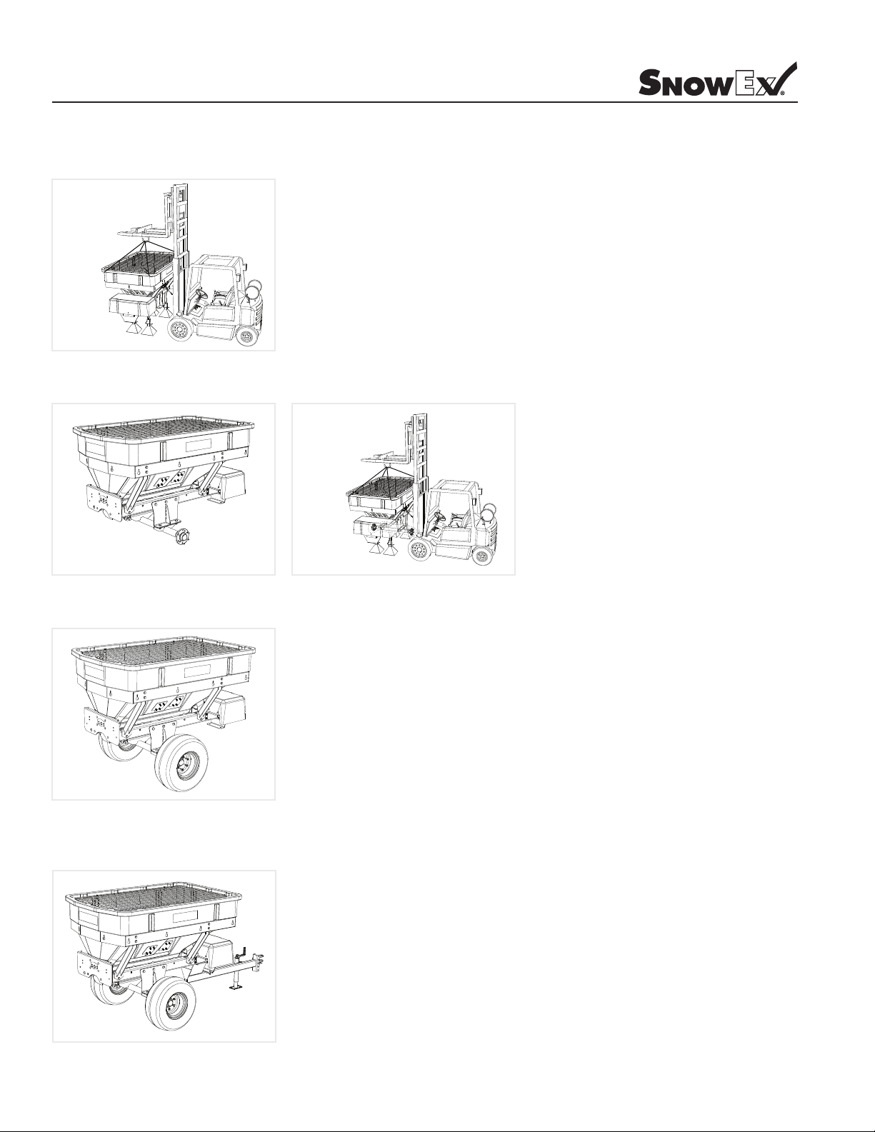
STEP 4
Lift the spreader and support it to allow installation of the axle and trailer tongue. Once lifted, remove and discard the pallet. As a safeguard,
in addition to the support jacks underneath the spreader, leave the lifting device in place.
STEP 5
Fasten the Axle to the frame.
STEP 6
Mount the wheels, tighten the lug nuts.
STEP 7
Attach the tongue. It bolts directly to the frame and to the hitch mount at the front of the trailer. Connect the leads of the trailer harness to the
control board: Red to “BAT +” and Black to “GROUND”. Put the Hitch Pin and Hair Pin through the clevis.
4 © TrynEx International 2014 F51558 REV-A140905
 Loading...