

SnowEx SP-1225G User Manual

This Manual Must Be Read Before Operating The Equipment
Owner / Operator’s Manual
FOR MODELS
SP-725G
SP-1225G
Madison Heights, Michigan 48071
800-725-8377
www.snowexproducts.com
© Trynex International 2011 (REV 001) L1102
Customers Copy
5 – 1

Table of Contents
General Information ...................................................................................................................................................................................... 3
Introduction ................................................................................................................................................................................................. 4
Safety .......................................................................................................................................................................................................... 5
Operating the Spreader ............................................................................................................................................................................. 6-7
Spreader Maintenance ................................................................................................................................................................................. 8
Assembly Istructions ..................................................................................................................................................................................... 9
Warranty .................................................................................................................................................................................................... 10
Side and Bottom View Model
# SP-725G/SP-1225G ................................................................................................................................................................. 11
Frame Assembly Parts Breakdown
Model # SP-725G ................................................................................................................................................................... 12-13
Model # SP-1225G ................................................................................................................................................................ 14-15
Drive Assembly Parts Breakdown .......................................................................................................................................................... 16-17
Notes .................................................................................................................................................................................................... 20-21
5 – 2
Have a question or need assistance?
SnowEx Customer Care
(800) 725-8377
or (248) 586-3500
Monday through Friday 8:00 AM to 4:30 PM EST
Fax: (248) 691-8378
E-Mail: customercare@trynexfactory.com
Website: www.snowexproducts.com
© Trynex International 2011 (REV 001) L1102

General Information
CONGRATULATIONS!
The spreader you have purchased is an example of snow and ice control technology at its fi nest! Your spreader’s self-contained design is a
trademark of all SnowEx products. Here’s why…
SIMPLICITY: Fewer moving parts manufactured of higher quality means minimal maintenance for your SnowEx spreader.
RELIABILITY: High impact linear low density polyethelyne hopper. State-of-the-art electronic dual variable speed control, custom engineered
powder coated frame, maximum torque 12-volt motor coupled to a custom engineered transmission; found only on SnowEx products.
VERSATILITY: Multi-use capabilities allows spreading of a variety of materials for snow and ice control.
WARRANTY: Best in the industry, hands down! 2 years standard and now 5 year extended (optional).
The benefi ts you are about to recognize are that of time, money and effort.
We welcome you to the world of SnowEx Performance.
Registration
Record the following information in this manual for quick reference.
Spreader Model Number
Spreader Serial Number
Date of Purchase
Dealer Where Purchased
When ordering Parts, the above information is necessary. This will help to see that you
receive the correct parts.
At the right is a diagram of the ID tag. This tag on the spreader is located on the frame.
Please fi ll out the warranty card with all the necessary information to validate it.
This will also give us a record so that any safety or service information can be
communicated to you.
Madison Heights, MI 48071
U.S.A.
1-800-725-8377
www.trynexfactory.com
SP-1225G
Model No.
Serial No.
U3-000000
© Trynex International 2011 (REV 001) L1102
5 – 3
Introduction
This manual has been designed for your help. It will assist you and instruct you on the proper set-up, installation and use of this spreader.
Refer to the table of contents for an outline of this manual.
We require that you read and understand the contents of this manual completely (especially all safety information) before attempting any
procedure contained herein.
THIS SIGN SHOULD ALERT YOU:
The Society of Automotive Engineers has adopted this SAFETY ALERT SYMBOL to pinpoint characteristics
that, if NOT carefully followed, can create a safety hazard. When you see this symbol in this manual or on the
machine itself, BE ALERT! Your personal safety and the safety of others is involved.
Defi ned below are the SAFETY ALERT messages and how they will appear in this manual:
(RED)
Information that, if not carefully followed,
can cause death!
(ORANGE)
Information that, if not carefully followed,
can cause serious personal injury or death!
(YELLOW)
Information that, if not carefully followed,
can cause minor injury or damage to equipment
5 – 4
© Trynex International 2011 (REV 001) L1102
Safety
Before attempting any procedure in this book, these safety instructions must be read and understood by all workers who have any part in the
preparation or use of this equipment.
For your safety warning and information decals have been placed on this product to remind the operator of safety precautions . If anything
happens to mark or destroy the decals, please request new ones from SnowEx.
Remember, most accidents are preventable and caused by human error. Exercising of care and precautions
must be observed to prevent the possibility of injury to operator or others!
Never operate equipment when under the infl uence of alcohol, drugs, or medications that might alter your
judgment and/or reaction time.
Before working with the spreader, secure all loose fi tting clothing and unrestrained hair.
Always wear safety glasses with side shields when servicing spreader. Failure to do this could result in
serious injury to the eyes.
Never allow children to operate or climb on equipment.
Always check areas to be spread to be sure no hazardous conditions or substances are in the area.
Always inspect unit for defects: broken, worn or bent parts, weakened areas on spreader.
Remember it is the owner’s responsibility to communicate information on safe usage and proper
maintenance of all equipment.
Always make sure personnel are clear of areas of danger when using equipment.
Never weld or grind on equipment without having a fi re extinguisher available.
Inspect the unit periodically for defects. Parts that are broken, missing or worn out must be replaced
immediately. The unit or any part of it can not be altered without prior written permission from the
manufacturer.
Always inspect pins whenever attaching or detaching spreader, and before operation of spreader.
Never exceed 10 m.p.h. when loaded spreader is attached to vehicle. Braking distances may be increased
and handling characteristics may be impaired at speeds above 10 m.p.h.
Never use wet materials or materials with foreign debris with any of these spreaders. These units are
designed to handle dry, clean, free fl owing material.
Never leave material in hopper for long periods of time. Be aware that all ice melters are hygroscopic and will
attract atmospheric moisture and harden up.
© Trynex International 2011 (REV 001) L1102
5 – 5
Operating the Spreader
Model # SP-725G/SP-1225G
SPREADER LOADING
WARNING – Do not overload vehicle. Use chart below to calculate weight of material. Weights of material are an average for dry
materials.
Material Weight Per Cubic Ft.
Rock Salt 80-90 lbs.
• Warning – Never leave material in hopper for long periods of time as salt is hygroscopic and will attract atmospheric moisture and harden up.
SPREADING TIPS
• Spread ice melters with the storm to prevent unmanageable levels of ice.
• Never exceed 10 m.p.h. when spreading.
• For a wider pass, increase speed.
• For a heavier pass, drive slower.
• Never operate spreader near pedestrians.
• Calculate spread pattern when near vegetation.
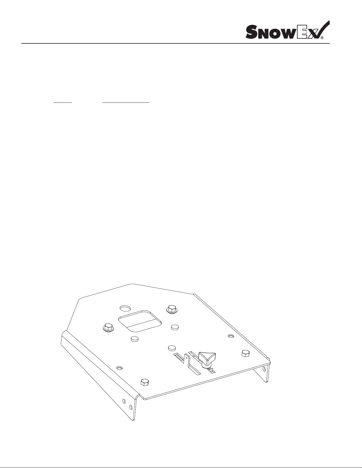
Gate Operation
1) To adjust the amount of material fl ow simply loosen knob and slide to the desired location and retighten knob. (see picture below)
5 – 6
© Trynex International 2011 (REV 001) L1102
Operating the Spreader (continued)
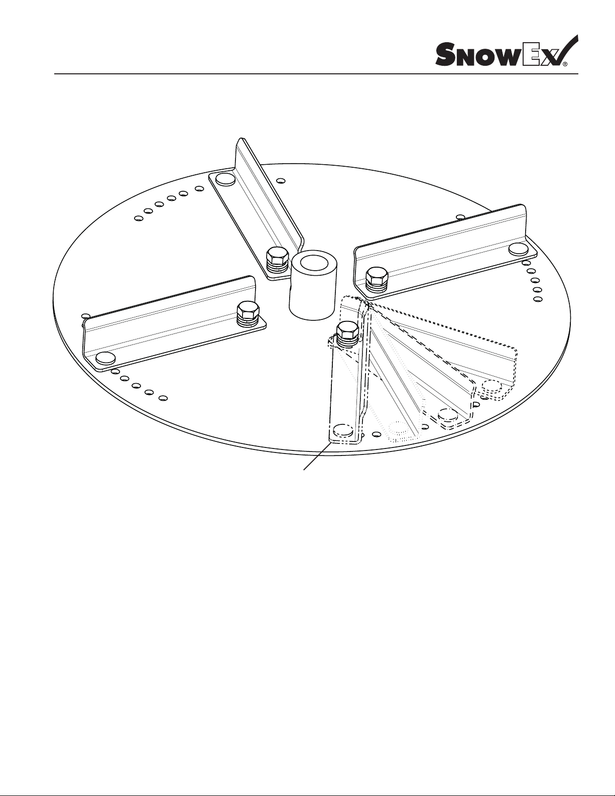
Model # SP-725G/SP-1225G
Adjustable Fins Shown in
Lift This End Up and
Move To Desired Position.
The purpose of the adjustable fi n is to provide a way to adjust spread patterns with different materials. You can select the desired position by
simply lifting up on the outside top edge. You will notice that diffrent materials act in different ways in relation to spinner speed. By moving
the fi ns you will be able to correct most pattern issues without having to sacrifi ce spinner speed. All adjustments should be made on pav-
ment and positions noted for future reference, this process should be incorporated into your normal calibration process.
Different Positions.
© Trynex International 2011 (REV 001) L1102
5 – 7
 Loading...