

SnowEx PMT-175 User Manual
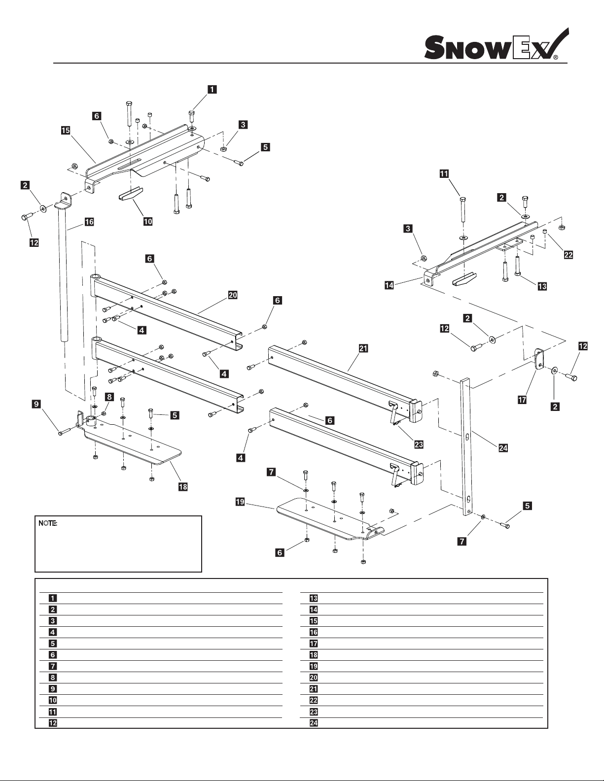
Pivot Mount Parts Breakdown
Model #PMT-175
NOTE: See Installation Warning
(Packaged with Kit) Before Drilling Holes.
NOTE:
When installing the Pivot Mount, if any movement is
noted with Rail Brackets due to weakened or altered
conditions of pick-up bed, drill and bolt through
pre-punched Rail Brackets to assure rm mounting.
yeK
D 4116 1/2-13 x 1-1/2” Hex Bolt
D 4119
D 4120
D 4121
D 4122
D 4124
D 4125
D 6138
D 6139
D 6141
D 6142
D 6143
.oN traP
1/2” Flat Washer
1/2” Lock Nut
3/8-16 x 1” Hex Bolt
3/8-16 x 1-1/2” Hex Bolt
3/8 Lock Nut
3/8 Flat Washer
5/16 Lock Nut
5/16-18 x 2” Hex Bolt
1/2” Toggle
1/2-13 x 4” Hex Bolt Full Thread
1/2-13 x 1-1/4” Hex Bolt
.ytQ noitpircseD
2
7
5
16
13
29
9
1
1
2
2 2
3 1
yeK
D 6144
D 6200
D 6201
D 6202
D 6203
D 6204
D 6205
D 6206
D 6207
D 6208
D 6222
D 6223
.oN traP
1/2-13 x 3” Hex Bolt Full Thread
Bed Rail Bracket Right
Bed Rail Bracket Left
Pivot Tube Assembly
Angle Top
Pivot Bumper Bracket
Latch Bumper Bracket
Pivot Channel Assembly
Latch Channel Assembly
Rubber Tip Protector
1/8” x 2-1/16” Hair Pin Clip
Latch Bar
4
1
1
1
1
1
1
2
2
4
.ytQ noitpircseD

Pivot Mount Installation Instructions
Model #PMT-175
Step 1: Insert upper & lower pivot rails into main frame of spreader. Line up the pre-punched holes on the pivot rail with
the main frame, then bolt together. Holes are pre-determined and can be relocated if spreader is not centered on vehicle.
Step 2: Locate top bed rail mounting brackets and set on top of pickup bed rails; Center by moving out towards the bumper.
maintain a minimum of 2” clearance between tailgate and spreader.
Step 3: Locate left and right bumper brackets. The left side or the pivot side will have a two piece system that will act as the
hinge for the spreader. (See g. D) The right side will have a two-piece system that will be the latching side. (See g. H). Attach
pivot tube and latch bar to the bumper plates using the posts as centering guides. Line up with the bed rail brackets. Be sure
that the tailgate will open before locating any of these brackets permanently. Make sure bumper brackets are parallel to the
lower main frame so that everything will be straight. After aligning all pieces, mark & drill holes using the bumper
guide. (As seen in Fig. A) Once holes have been drilled bolt securely to bumper. Note: Use a minimum of 3 holes.
Step 3-A: If installing on a newer Chevrolet vehicle with a bumber that has raised ends, you will need to install one inch
spacers supplied with kit PMT-175-C (see pg. 7-38) for illustration.
Step 4: Locate toggle bolt assembly and install on left and right upper bed rail brackets as seen in (Fig. B). Position toggle
bolt (Fig. C) to keep in position while tightening. Pull up on the bracket to keep a slight amount of pressure on the toggle
bolt . *NOTE*
assembly. Take the two 3” full threaded bolts and screw into bottom of bed rail brackets. Use rubber tip protectors on bolt
end as seen in (Fig E). Torque bolts down using a HAND RATCHET ONLY
blue removable thread locker. Do this only as a nal assembly once you have proper tailgate clearance established.
Step 4A: Please make sure toggle is positioned so front to back in line with vehicle, this is very important. If the toggle makes
contact with the rear inside surface of the pickup box, you may cause an internal dent that will show on the exterior of the
box. Also
Please take your time during this step and be sure it is done correctly.
: When tightening toggle bolt assembly, do not exceed 30 foot pounds of torque, or you may damage toggle
- you may also want to use a small amount of
you can damage the paint which can be very costly to repair, not to mention a huge inconvenience for everyone.
plates as a
Step 5: Now that the lower bumper brackets and upper bed rail brackets are mounted, you will now need to check both the
pivot tube assembly and latch bar to see if these need to be cut down. Due to the variety of truck bumpers, bed rail heights,
etc, we made these two parts intentionally too long. On the pivot side you will need to align the top of the pivot tube hole to
the left side bed rail bracket hole. Trim o the amount needed with a cut o saw.
Step 6: Put this piece aside for now. Now that you have the pivot side assembly cut to length, mount spreader main frame
assembly to truck. With an assistant, place pivot side of spreader on truck. Take pivot tube assembly and insert
through pivot rails to the bumper plate locator tube. Bolt the upper pivot tube assembly to the bed rail bracket.
Make sure bed rail bracket is secure.
the bumper. Drill a 5/16” hole, (as seen in Fig D) and bolt lower portion of pivot tube assembly. This will now complete pivot
side installation.
Step 7: The latching side will be done the same way, except that you will need to mount the locator bracket to the right side
bed rail bracket (see Fig F, G, H). Once you have completed, trim ush with the top of the locator bracket. After cutting bar to
proper length, drill a 1/2” hole in mounting bar. Bolt the upper portion and the lower portion of the latching bar.
Step 8: Locate latching rails and insert into spreader main frame, position the latch rails so they are latched to the latching
bar. Center latching bar in the pocket of the end of the latch rail. (see Fig. F) This will insure proper latching when closing
spreader.
Step 9: Using an assistant or a large vice grip to insure rails do not move, drill three 3/8” holes using the pre-punched holes
as a guide. Repeat this process for the lower rail also. Bolt together. This
Step 10: Drill four more 3/8” holes as seen in (Fig I) to stien the whole frame/rail system. Bolt together. This will insure
minimum frame deection under extreme load conditions.
Step 11: Make sure spreader is level and clear from the tailgate when closed. You can make minor adjustments by loosening
the bed rail brackets (one at a time) and trimming the unit out. Also at this time you may want to apply a small amount of
removable thread locker to insure the bolts stay secure.
Swing spreader until both support pads on lower main frame rail are completely on
completes the latch side of the pivot mount.
Step 12: Lube zerk ttings on pivot tubes.
Step 13: IMPORTANT: When installing the Pivot Mount, if any movement is noticed with the bed rail brackets due to weakness
or altered conditions of pickup bed, drill and bolt thru the pre-punched holes located on the sides of the bed rail brackets
and bolt securely.
Step 14: After rst use, tighten all nuts and bolts on mount and spreader.
 Loading...