

SnowEx Liqui Maxx 170802 Owner's Manual And Installation Instructions
November 15, 2018
Lit. No. 76616, Rev. 02
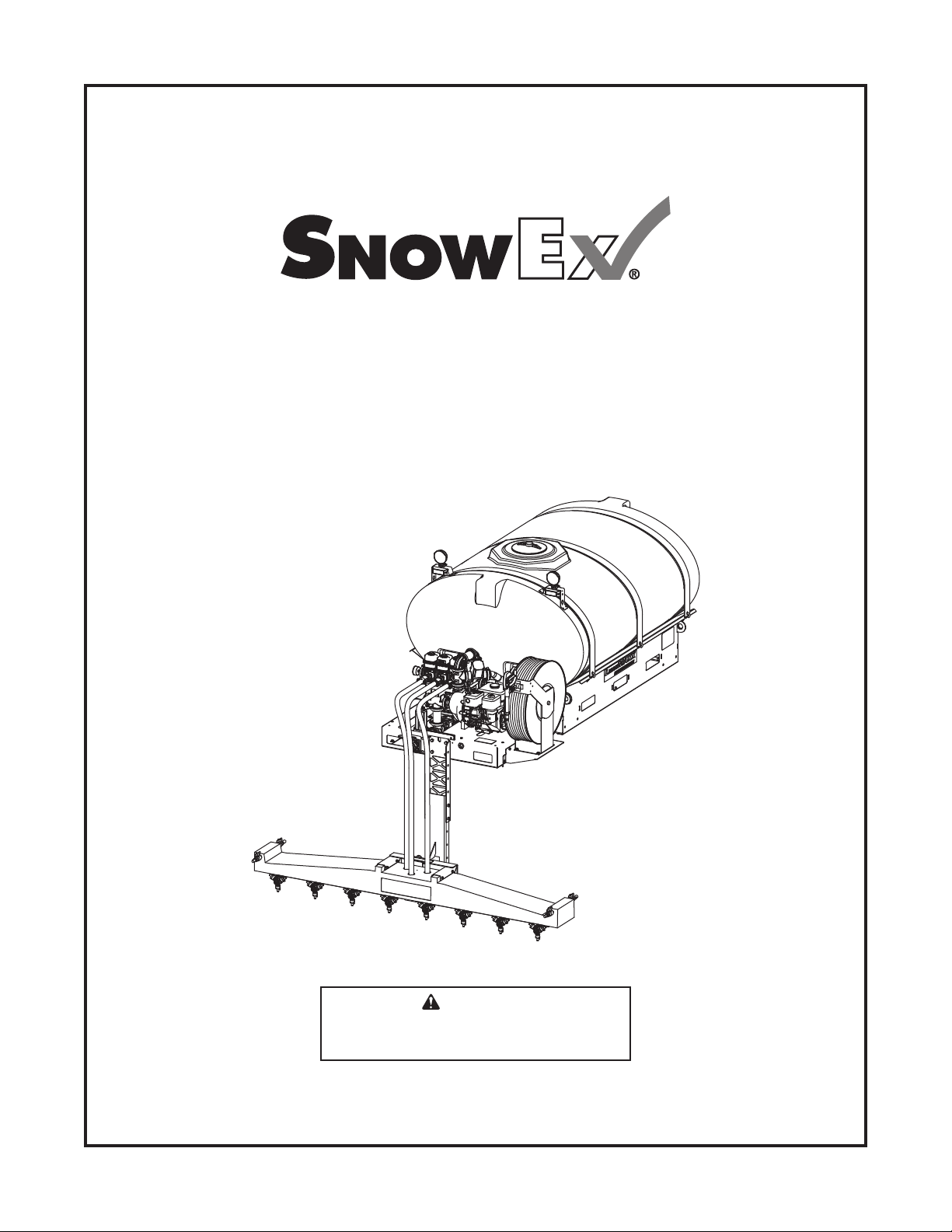
Liqui Maxx™ Sprayer Systems
Owner's Manual and Installation Instructions
Original Instructions
CAUTION
Read this document before operating
or servicing the equipment.
This manual and instructions are for Liqui Maxx Sprayer Systems
with serial numbers beginning with 170802 and higher.
This document supersedes all editions with an earlier date.


TABLE OF CONTENTS
PREFACE ....................................................................4
Warranty Registration ........................................... 4
Owner's Information Form ....................................4
SAFETY ...................................................................... 5
Safety Defi nitions .................................................. 5
Warning/Caution Labels ....................................... 5
Serial Number Label ............................................. 6
Safety Precautions ................................................ 6
Fuses ....................................................................7
Personal Safety..................................................... 7
Fire and Explosion ................................................ 8
Cell Phones ...........................................................8
Ventilation .............................................................8
Battery Safety ....................................................... 8
Torque Chart ......................................................... 8
LOADING .................................................................... 9
Certifi cation ........................................................... 9
Specifi cations ........................................................ 9
INSTALLATION INSTRUCTIONS ............................ 10
Installation and Removal ..................................... 10
Control Box Mounting ......................................... 12
Wiring Diagram ................................................... 13
Installation ........................................................... 14
Mounting the Display Console & Switches ... 14
Speed Sensor Installation ............................ 15
Standard Control Installation .............................. 15
Wiring Diagram ............................................. 15
Battery Connections ..................................... 15
FILLING .................................................................... 16
First Time Filling .................................................. 16
Routine Filling ..................................................... 16
Gasoline ....................................................... 16
Adding Brine ................................................. 16
Oil ................................................................. 16
OPERATING & CALIBRATION INSTRUCTIONS ... 18
Control Operation ............................................... 18
Deluxe Control .............................................. 18
Standard Control .......................................... 19
Deluxe Console Functions .................................. 20
Rotary Switch Position Functions ................. 20
Calibration Positions ..................................... 20
Soft Key Functions .......................................20
Calibration ........................................................... 21
Entering Calibration Values .......................... 21
"Special" Calibration ........................................... 24
Entering Calibration Values .......................... 24
Console Switches & Buttons...............................28
Section Switches .......................................... 28
Resetting System Counters .......................... 29
Standard Sprayer Control ................................... 30
Sprayer Console ........................................... 30
Spray Boom Operation .......................................30
Wing Spray Nozzle Selection ....................... 30
Downward Spray Nozzle Selection .............. 31
Nozzle Alignment ......................................... 31
Default Control Settings ...................................... 31
Deluxe Control .............................................. 31
Application Rates ................................................ 32
Manual Mode ................................................ 32
Calculations ........................................................ 33
Equations ...................................................... 33
Conversions.................................................. 33
Example Calculation .....................................34
MAINTENANCE ........................................................35
Periodic Maintenance .........................................35
Cleaning .............................................................. 35
End of Season and Storage ................................ 35
Nozzle Maintenance ...........................................35
Pump Maintenance ............................................. 35
TROUBLESHOOTING .............................................. 36
TROUBLESHOOTING – DELUXE CONTROL ........37
Wiring Diagram – Electric Start System ............. 38
Wiring Diagram – Hydraulic System ................... 39
Lit. No. 76616, Rev. 02 3 November 15, 2018

PREFACE
This manual has been prepared to acquaint you with
the safety information, operation, and maintenance of
your new machine. Improper installation and operation
could cause personal injury and/or equipment and
property damage. Read and understand the Owner's
Manual before installing, operating, or making
adjustments. Keep this manual accessible.
®
When service is necessary, call SnowEx
Service at 1-800-SALTERS (725-8377).
NOTE: This unit is designed to be used with
salt brine; the use of additives may impact
performance.
NOTE: Do not modify or alter the machine.
Altering the unit in any way will void the warranty.
The Liqui Maxx™ Sprayer System is designed to apply
brine to pre-treat, anti-ice, and post-treat parking lots
and roadways. Each Liqui Maxx unit consists of a
holding tank, pumping system and control, and a spray
boom.
Technical
Standard Control
The standard version of the control has the ability
to turn the sprayers ON and OFF and increase or
decrease the pressure of the system from the cabin.
Deluxe Control
The deluxe version of the control unit has many
features that include: push-button controls, application
rate adjustment and selection, automatic and manual
control modes, visual and audio alarms, and a BLAST
function for spot applications.
A separate GPS unit is offered that incorporates the
vehicle speed to automatically adjust the fl ow rate
and maintain the desired application rate. The deluxe
control is also compatible with some vehicle speed
sensors that can replace the GPS unit. Consult your
vehicle owner's manual for more information.
WARRANTY REGISTRATION
Warranty registration is available online at
www.snowexproducts.com. Under "Support" select
"Warranty Registration" and submit the form online.
OWNER'S INFORMATION
Owner's Name: ______________________________________________________________________
Date Purchased: _____________________________________________________________________
Outlet Name: ______________________________________________ Phone: _________________
Outlet Address: ______________________________________________________________________
Vehicle Model: _______________________________________________ Year: _______________
Equipment Model: ____________________________________ Serial #: ______________________
Length: ________________________ Weight: __________________ lb/kg: _________________
Lit. No. 76616, Rev. 02 4 November 15, 2018
SAFETY
SAFETY DEFINITIONS
WARNING
Indicates a potentially hazardous situation
that, if not avoided, could result in death or
serious personal injury.
CAUTION
Indicates a potentially hazardous situation
that, if not avoided, may result in minor or
moderate injury. It may also be used to alert
against unsafe practices.
NOTE: Indicates a situation or action that can lead
to damage to your sprayer and vehicle or other
property. Other useful information can also be
described.
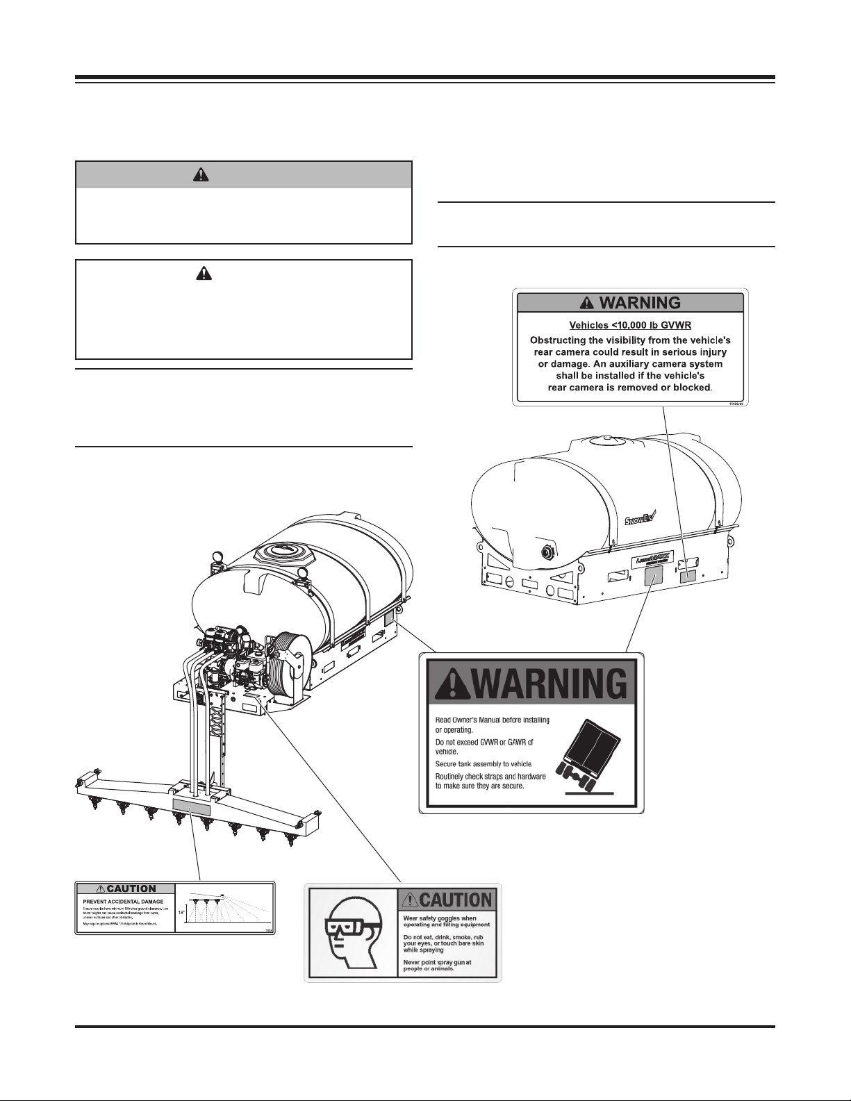
WARNING/CAUTION LABELS
Become familiar with and inform users about the
warning and caution labels on the machine.
If labels are missing or cannot be read, call
1-800-SALTERS (725-8377).
Model TSA-300 Only
Both Sides
Lit. No. 76616, Rev. 02 5 November 15, 2018

SAFETY
SERIAL NUMBER LABEL
SAFETY PRECAUTIONS
Improper installation and operation could cause
personal injury and/or equipment and property
damage. Read and understand labels and the
Owner's Manual before installing, operating, or making
adjustments.
WARNING
• Before working with the equipment, secure all
loose-fi tting clothing and unrestrained hair.
• Before operating the sprayer system, verify
that all safety guards are in place.
• Always shut vehicle OFF before attempting
to attach, detach, or service sprayer system.
• Never attempt to take a unit off a truck with
liquid in it.
• Do not climb into or ride on the machine.
WARNING
Overloading could result in an
accident or damage. Do not exceed
GVWR or GAWR ratings as found
on the driver-side vehicle door
cornerpost. See Filling section to determine
maximum volumes of spraying material.
Code Defi nition
YY 2-Digit Year
MM 2-Digit Month
DD 2-Digit Day
LL 2-Digit Location Code
XXXX 4-Digit Sequential Number
ZZZZZZ Model #
WARNING
Securely bolt and strap unit into place on the
vehicle bed using the optional UMK-200 bolt
kit and ratchet straps or similar. Unit must
be strapped down and bolted into position
before operating or transporting.
WARNING
Vehicle handling and characteristics will
change with the unit installed. Avoid any
sudden steering maneuvers, starts, or stops
that could create sloshing and instability.
WARNING
Always make sure that personnel are clear
of areas of danger when using equipment.
Maintain 60' distance from all bystanders
when operating the sprayer system.
Lit. No. 76616, Rev. 02 6 November 15, 2018
SAFETY
WARNING
Do not install the control for this product in
the deployment path of an air bag. Refer to
vehicle manufacturer's manual for air bag
deployment area(s).
WARNING
Inspect the unit periodically for defects. Parts
that are broken, missing, or worn out must be
replaced immediately. Do not alter any part of
the unit without prior written permission from
the manufacturer.
WARNING
Vehicles <10,000 lb GVWR: Obstructing the
visibility from the vehicle's rear camera could
result in serious injury or damage. An auxiliary
camera system shall be installed if the
vehicle's rear camera is removed or blocked.
CAUTION
Brine is typically a clear to cloudy white
liquid with no odor. It may be irritating to the
eyes, skin, and respiratory system. For more
safety information on brine and other de-icing
materials, refer to the manufacturer's Safety
Data Sheet (SDS).
CAUTION
During the sprayer system installation
we recommend the addition of an OSHA
compliant Backup Alarm. This alarm is
required for OSHA governed employers.
CAUTION
Disconnect electric and/or hydraulic power
and tag out, if required, before servicing or
performing maintenance.
CAUTION
Do not leave material in the unit for long
periods of time.
NOTE: Lubricate grease fi ttings after each use.
Use a good quality multipurpose grease.
FUSES
The electrical system contains several
automotive-style fuses. If a problem should occur and
fuse replacement is necessary, the replacement fuse
must be of the same type and amperage rating as
the original. Installing a fuse with a higher rating can
damage the system and could start a fi re.
PERSONAL SAFETY
• Remove ignition key and put the vehicle in PARK
or in gear to prevent others from starting the
vehicle during installation or service.
• Wear only snug-fi tting clothing while working on
your vehicle or sprayer system.
• Do not wear jewelry or a necktie, and secure long
hair.
• Wear safety goggles to protect your eyes from
brine, battery acid, gasoline, dirt, and dust.
CAUTION
• Do not operate a sprayer system in need of
maintenance.
• Before operating the sprayer system,
reassemble any parts or hardware removed
for cleaning or adjusting.
• Before operating the sprayer system,
remove materials such as cleaning rags,
brushes, and hand tools from the unit.
• Before operating the sprayer system, read
the engine owner's manual, if so equipped.
• While operating the unit, use auxiliary warning
lights, except when prohibited by law.
• Tighten all fasteners according to the
Torque Chart. Refer to Torque Chart for the
recommended torque values.
Lit. No. 76616, Rev. 02 7 November 15, 2018
• Do not eat, drink, smoke, rub your eyes, or touch
bare skin while spraying.
• Never point spray gun at people or animals.
• Avoid touching hot surfaces such as the engine,
radiator, hoses, and exhaust pipes.
• Always have a fi re extinguisher rated BC handy,
for fl ammable liquids and electrical fi res.
SAFETY
FIRE AND EXPLOSION
WARNING
Gasoline is highly fl ammable and gasoline
vapor is explosive. Never smoke while
working on vehicle. Keep all open fl ames
away from gasoline tank and lines. Wipe up
any spilled gasoline immediately.
Be careful when using gasoline. Do not use gasoline
to clean parts. Store only in approved containers away
from sources of heat or fl ame.
CELL PHONES
A driver's fi rst responsibility is the safe operation of
the vehicle. The most important thing you can do
to prevent a crash is to avoid distractions and pay
attention to the road. Wait until it is safe to operate
Mobile Communication Equipment such as cell phones,
text messaging devices, pagers, or two-way radios.
VENTILATION
WARNING
Vehicle exhaust contains lethal fumes.
Breathing these fumes, even in low
concentrations, can cause death. Never
operate a vehicle in an enclosed area without
venting exhaust to the outside.
BATTERY SAFETY
CAUTION
Batteries normally produce explosive gases
which can cause personal injury. Therefore,
do not allow fl ames, sparks, or lit tobacco
to come near the battery. When charging or
working near a battery, always cover your
face and protect your eyes, and also provide
ventilation.
• Batteries contain sulfuric acid, which burns
skin, eyes, and clothing.
• Disconnect the battery before removing or
replacing any electrical components.
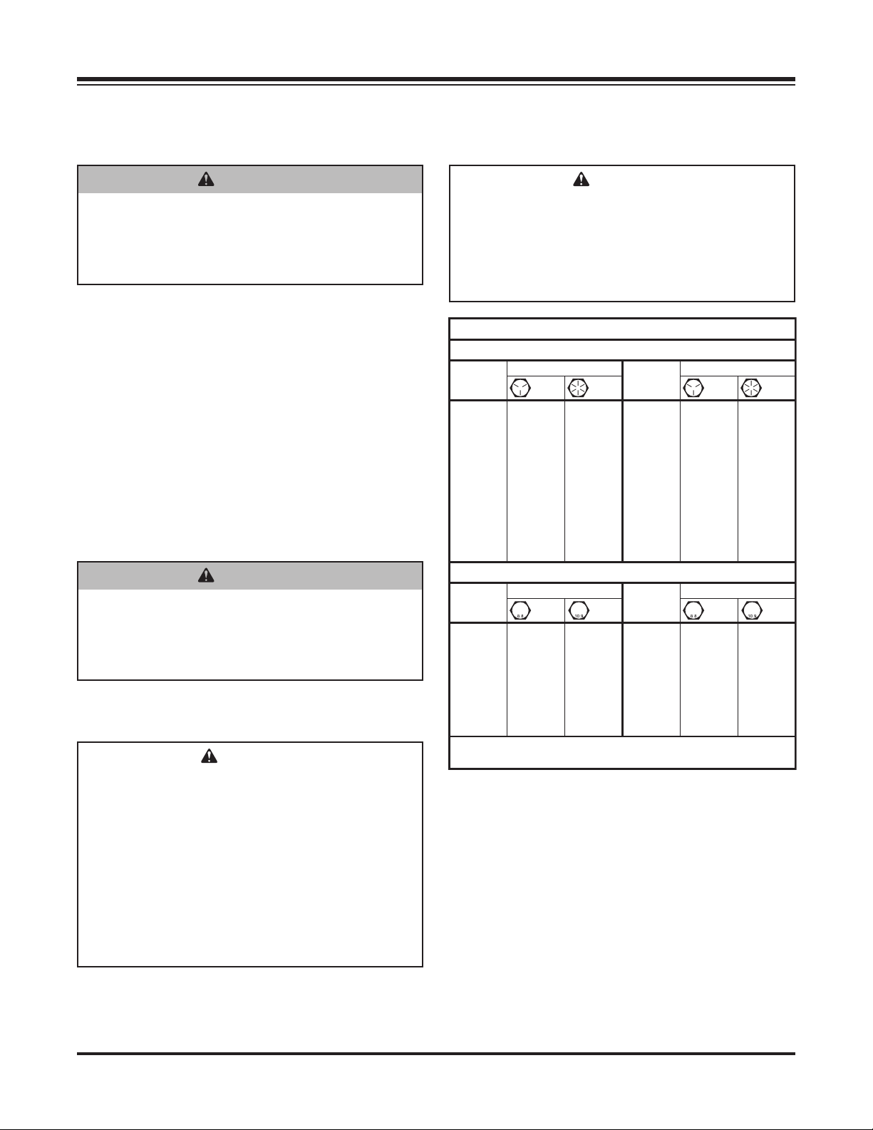
TORQUE CHART
CAUTION
Read instructions before assembling.
Fasteners should be fi nger tight until
instructed to tighten according to the Torque
Chart. Use standard methods and practices
when installing equipment, including proper
personal protective safety equipment.
Recommended Fastener Torque Chart
Inch Fasteners Grade 5 and Grade 8
Size Size
1/4-20 109 154
1/4-28 121 171
5/16-18 150 212
5/16-24 170 240
3/8-16 269 376
3/8-24
7/16 -14
7/16 -20
1/2-13
1/2-20
Tor qu e (ft-l b)
Grade
5
8.4
9.7
17.4
19.2
30.8
35.0
49.4
55.2
75.3
85.0
106.4
120. 0
Grade
11. 9
13.7
24.6
27.3
43.6
49.4
69.8
77.9
8
9/16-12
9/16-18
5/8-11
5/8-18
3/4-10
3/4-16
7/8 -9
7/8 -14 474 66 9
1-12 704 995
Metric Fasteners Class 8.8 and 10.9
Size Size
M6 x 1.00
M8 x 1.25
M10 x 1.50
M12 x 1.75
M14 x 2.00
M16 x 2.00
M18 x 2.50 318222
Tor qu e (ft-l b)
Class
8.8
7.7
19.5
38.5
67
107
167
These torque values apply to fasteners
except those noted in the instructions.
Class
26.9
53.3
93
148
231
10.9
M20 x 2.5011.1
M22 x 2.50
M24 x 3.00
M27 x 3.00
M30 x 3.50
M33 x 3.50
M36 x 4.00
Tor qu e (ft-l b)
Grade
5
297 420
429 60 6
644 9091-8
Tor qu e (ft-l b)
Class
8.8
325
428
562
796
1117
1468
1952
Grade
8
Class
10.9
450
613
778
113 9
1545
2101
2701
Lit. No. 76616, Rev. 02 8 November 15, 2018
LOADING
This Owner's Manual covers vehicles that have been
recommended for carrying the sprayer system. Please
see your local dealer for proper vehicle applications.
CERTIFICATION
WARNING
New untitled vehicle installation of a sprayer
system requires National Highway Traffi c
Safety Administration altered vehicle
certifi cation labeling. Installer to verify that
full sprayer does not exceed GVWR or GAWR
rating label and complies with FMVSS.
WARNING
Overloading could result in an accident or
damage. Do not exceed GVWR or GAWR as
found on the driver-side cornerpost of vehicle.
CAUTION
Read and adhere to manufacturer's
ice-control material package
labeling, including Material Safety
Data Sheet requirements.
SPECIFICATIONS
Liqui Maxx™ Sprayer System
Tank Model TSA-300 TSA-500 TSA-750 TSA-1250
Capacity (gal) 300 500 750 1250
Tank and Pump
Dimensions (in)
Empty Unit Weight (lb) 500 600 700 1000
Full Unit Weight (lb) 3500 5600 8200 13500
Suggested Gross Vehicle
Weight Rating (GVWR) (lb)
Vehicle Class Class 2B Class 4 Class 5 Class 6
Length 101 112 118 119
Width 53 59 75 85
Height 24 48 55 73
8,500–10,000 14,000–16,000 16,000–19,500 19,500–26,000
Lit. No. 76616, Rev. 02 9 November 15, 2018
INSTALLATION INSTRUCTIONS
WARNING
Overloading could result in an
accident or damage. Do not exceed
GVWR or GAWR ratings as found
on the driver-side vehicle door
cornerpost. See Specifi cations to determine
maximum volumes of spraying material.
WARNING
New untitled vehicle installation of a sprayer
system requires National Highway Traffi c
Safety Administration altered vehicle
certifi cation labeling. Installer to verify that
full sprayer does not exceed GVWR or GAWR
rating label and complies with FMVSS.
WARNING
Always shut vehicle OFF before attempting to
attach, detach, or service sprayer system.
WARNING
Never attempt to take a unit off a truck with
liquid in it.
INSTALLATION AND REMOVAL
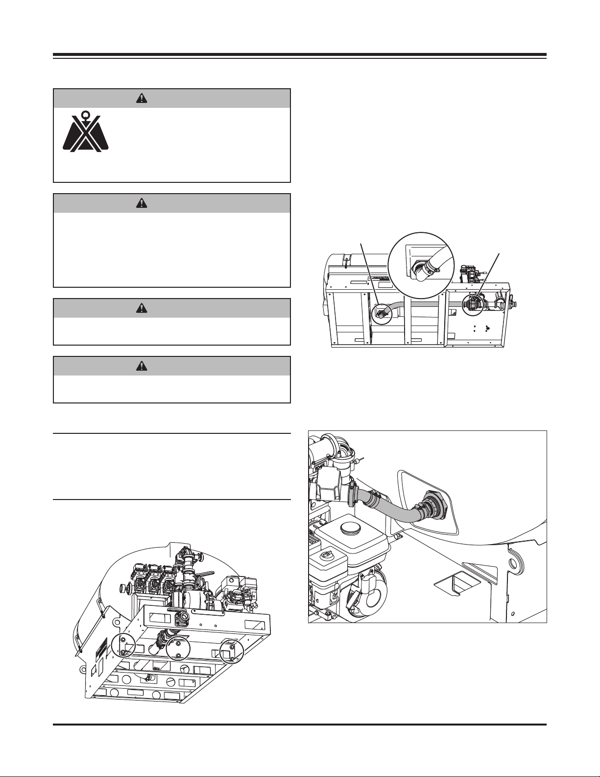
2. Connect the hose underneath the unit:
Securely fasten the 90° elbow connection to the
tank bulkhead fi tting underneath the unit. Make
sure that the bulkhead fi tting is securely fastened
to the tank to prevent leaks. Run the 2" hose from
the elbow to the shut-off valve below the pump.
Clock the 90° elbow so that the hose remains free
of kinks; cut it to length. Clamp the hose using
two (2) clamps on each end to prevent leaks. In
low temperatures, warming the hose may ease
installation. Dip the hose in hot water or carefully
use a heat gun for 20– 40 seconds.
90° Elbow
Shut-Off Valve
3. Connect the servo valve to the 1-1/2" bulkhead
fi tting on the pump side of the brine tank with
supplied 1-1/2" fl exible hose. Insert 1-1/2" hose
barb into bulkhead fi tting with pipe dope. Tighten
securely. Cut hose to length and attach with four
provided hose clamps.
NOTE: To prevent leaks, use a thread-sealing
compound on all threaded connections. Do
not use Tefl on® tape, as fragments will clog the
spray nozzles. Clamped connections may require
periodic retightening.
1. Bolt the pump and tank platforms together
(six places).
Tefl on® is a registered trademark of E. I. du Pont de Nemours and Company.
4. Lift the main tank and pump assembly using the
fork lift pockets. Use caution when inserting forks.
Improper insertion may puncture or damage the
brine tank and tubing routed underneath the unit.
Center the tank and pumping system from driver's
side to passenger's side on top of the truck bed
and lower into position.
Lit. No. 76616, Rev. 02 10 November 15, 2018
INSTALLATION INSTRUCTIONS
5. Install any optional kits and equipment. To install the
BRM-175 Adjustable Boom Receiver Mount, unfasten
the rear brake light, install the kit, and re-install the
light on the top rear face of the BRM bracket.
6. Securely bolt and strap unit into place on the
vehicle bed using the optional UMK-200 Universal
Mounting Kit or similar brackets and ratchet straps.
Hardware attaching the sprayer system directly to
the vehicle is the responsibility of the end user.
NOTE: Pay special attention when drilling or
clamping dissimilar metals to aluminum bodies.
Galvanic corrosion can occur if not handled
properly. Contact vehicle manufacturer for
recommended attachment practices.
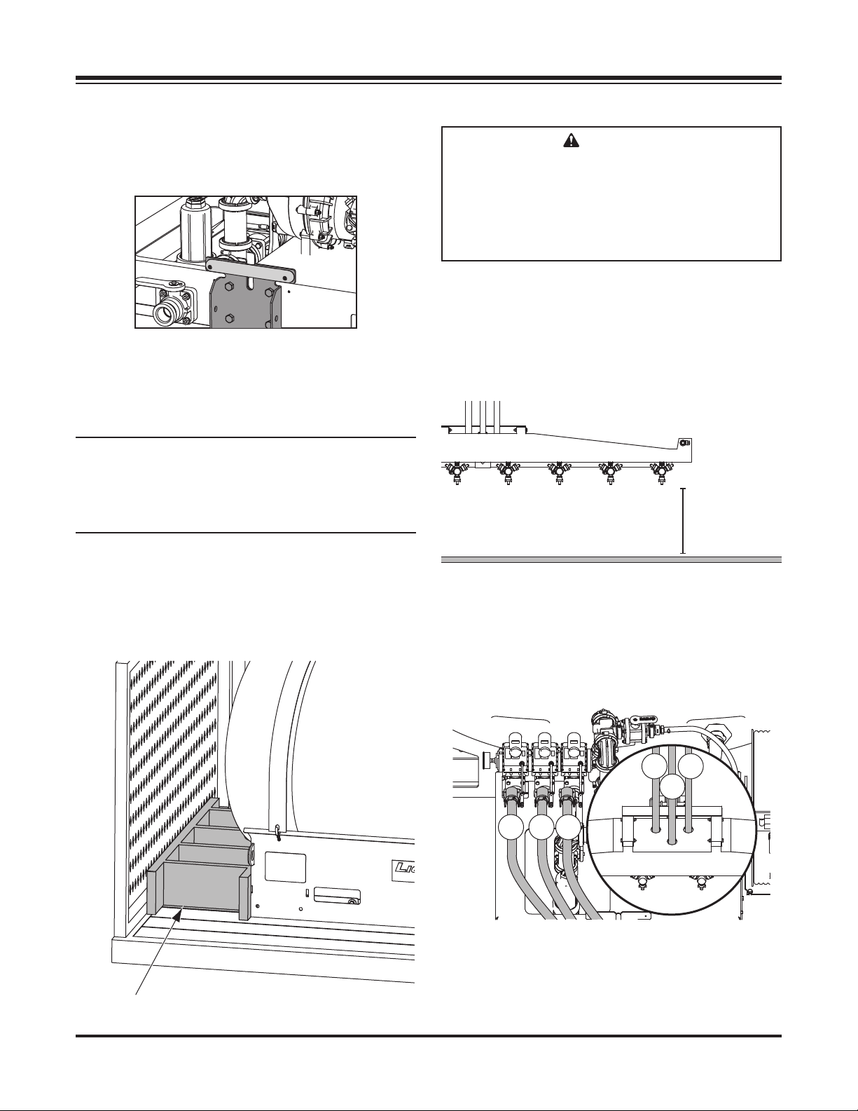
CAUTION
Ensure that nozzles have minimum 18 inches
ground clearance. Low boom heights can
cause accidental breakage from curbs,
uneven surfaces, and other obstacles.
Adjustment may require optional BRM-175
Adjustable Boom Mount.
8. Install the boom so that the nozzles measure
18"–22" from ground to nozzle tip. This is to
prevent damage and ensure optimal performance.
Consider using the optional BRM-175 Adjustable
Boom Receiver Mount if the tips of the nozzles lie
outside this zone when using your stock receiver
hitch.
18"–22"
7. Measure the distance between the front of the
truck bed and the tank base. Make a spacer to fi ll
area between the tank base and the front of the
truck bed. Failure to install this spacer could result
in damage to the sprayer and/or vehicle.
9. Connect the boom to the pump. Clamp the quick
disconnect attachments on the boom hoses to the
manifold valves on the pumping unit. Route the
hoses to the installed boom with adequate slack
and cut the hoses to fi t. Clamp the hose tightly to
the boom to prevent leaks.
1
3
2
1
2 3
Wood Spacer
Lit. No. 76616, Rev. 02 11 November 15, 2018
INSTALLATION INSTRUCTIONS
CONTROL BOX MOUNTING
NOTE: Use dielectric grease to prevent corrosion
on all connections.
Before beginning the installation, remove all battery
cables from the vehicle battery terminals.
1. Route the vehicle harness (PN 72141) along the
vehicle frame. Do not route it close to the exhaust
system or engine, where extreme heat could melt
the wiring insulation and short out the sprayer and
vehicle electrical systems. Attach the harness to
frame holes and frame supports. Do not attach
to fuel or brake lines. Use heavy-duty cable ties
or frame clamps to fasten the harness along the
frame.
CAUTION
Before drilling holes, check to see that no
vehicle wiring or other components could be
damaged.
2. Route the control harness (PN 72143) using
an existing access hole through the fi re wall
into the vehicle cab. If adding an access hole is
necessary, check the area on the other side of
the fi re wall to make sure that you will not drill
into vehicle wiring or other components. Attach
securely with cable ties.
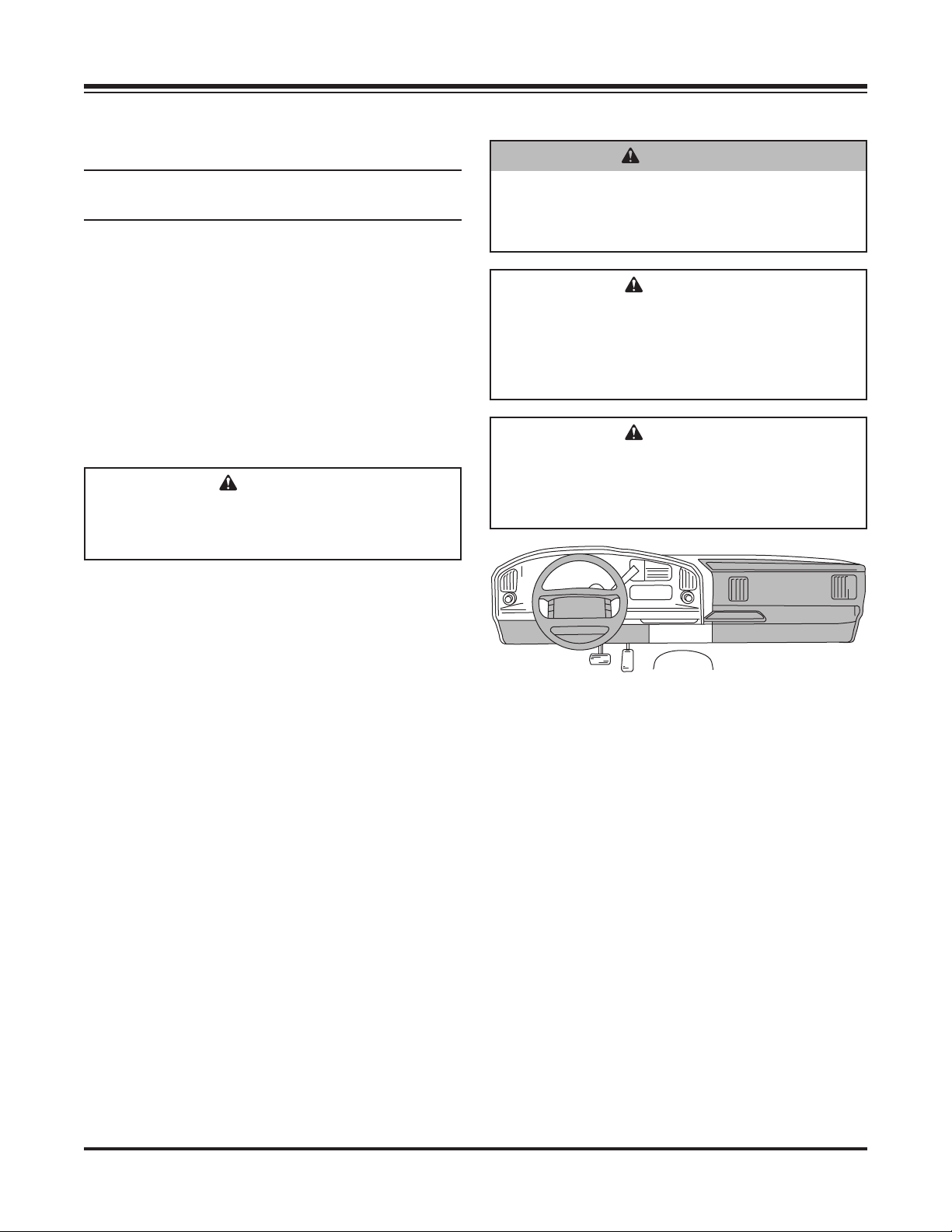
WARNING
Do not install the control for this product in
the deployment path of an air bag. Refer to
vehicle manufacturer's manual for air bag
deployment area(s).
CAUTION
Do not mount the control close to any heater
vents or in areas prohibited by the vehicle
manufacturer for crashworthiness. See
the vehicle's body builder's book, owner's
manual, or service manual for details.
CAUTION
Do not alter, modify, or install component in
shaded areas shown below. Failure to comply
may interfere with air bag deployment or
cause injury to operator in an accident.
3. Connect the harness to the back of the control
(PN 72145) and mount the control in a suitable
location within easy reach of the vehicle operator
without restricting access to the vehicle controls
and instruments.
4. Connect the harness to the battery. Refer to the
wiring diagrams for battery connections.
Lit. No. 76616, Rev. 02 12 November 15, 2018
 Loading...