

SnowEx Junior 325 User Manual

Spreaders for Snow & Ice Control
FOR MODELS
Bulk-Pro 1875
5701 orP-toviP
Mini-Pro 575
Junior 325
© Trynex International 2009 (REV004) L1040
7 — 1

Table of Contents
INTRODUCTION . . . . . . . . . . . . . . . . . . . . . . . . . . . . . . . . . . . . . . . . . . . . . . . . . . . . . . . . . . . . . . . . . . . . . . . . . . . . . . . . . . . . . . . . . . . . . . . . . . . . . . 3
GENERAL INFORMATION AND REGISTRATION . . . . . . . . . . . . . . . . . . . . . . . . . . . . . . . . . . . . . . . . . . . . . . . . . . . . . . . . . . . . . . . . . . . . . . . . . . . . 4
SAFETY PRECAUTIONS . . . . . . . . . . . . . . . . . . . . . . . . . . . . . . . . . . . . . . . . . . . . . . . . . . . . . . . . . . . . . . . . . . . . . . . . . . . . . . . . . . . . . . . . . . . . . . 5-6
• PREPARATION
• OPERATIONS
• SERVICE
SPREADER PARTS/DIAGRAMS . . . . . . . . . . . . . . . . . . . . . . . . . . . . . . . . . . . . . . . . . . . . . . . . . . . . . . . . . . . . . . . . . . . . . . . . . . . . . . . . . . . . . . 7-13
• BULK PRO 1875
• PIVOT PRO 1075
• MINI PRO 575
• DRIVE MOTOR ENCLOSURE ASSEMBLY
• JUNIOR 325
WIRING INSTRUCTIONS . . . . . . . . . . . . . . . . . . . . . . . . . . . . . . . . . . . . . . . . . . . . . . . . . . . . . . . . . . . . . . . . . . . . . . . . . . . . . . . . . . . . . . . . . . . . 14-20
BLANK PAGE . . . . . . . . . . . . . . . . . . . . . . . . . . . . . . . . . . . . . . . . . . . . . . . . . . . . . . . . . . . . . . . . . . . . . . . . . . . . . . . . . . . . . . . . . . . . . . . . . . . . . . . . 21
OPERATING THE SPREADER . . . . . . . . . . . . . . . . . . . . . . . . . . . . . . . . . . . . . . . . . . . . . . . . . . . . . . . . . . . . . . . . . . . . . . . . . . . . . . . . . . . . . . 22-23
ADJUSTABLE DEFLECTOR . . . . . . . . . . . . . . . . . . . . . . . . . . . . . . . . . . . . . . . . . . . . . . . . . . . . . . . . . . . . . . . . . . . . . . . . . . . . . . . . . . . . . . . . . 24-25
GATE ASSEMBLY . . . . . . . . . . . . . . . . . . . . . . . . . . . . . . . . . . . . . . . . . . . . . . . . . . . . . . . . . . . . . . . . . . . . . . . . . . . . . . . . . . . . . . . . . . . . . . . . . . 26-27
VIBRATOR KIT . . . . . . . . . . . . . . . . . . . . . . . . . . . . . . . . . . . . . . . . . . . . . . . . . . . . . . . . . . . . . . . . . . . . . . . . . . . . . . . . . . . . . . . . . . . . . . . . . . . . . . . 28
SPREADER MOUNT PARTS/DIAGRAMS . . . . . . . . . . . . . . . . . . . . . . . . . . . . . . . . . . . . . . . . . . . . . . . . . . . . . . . . . . . . . . . . . . . . . . . . . . . . 29-42
• RECEIVER HITCH MOUNT
• PIVOT MOUNT
• 3-POINT MOUNT
• TRAILER MOUNT
• DROP UTILITY MOUNT
• UTILITY MOUNT
• PIVOT PAL HITCH MOUNT
TROUBLESHOOTING . . . . . . . . . . . . . . . . . . . . . . . . . . . . . . . . . . . . . . . . . . . . . . . . . . . . . . . . . . . . . . . . . . . . . . . . . . . . . . . . . . . . . . . . . . . . . . 43-48
SPREADER MAINTENANCE . . . . . . . . . . . . . . . . . . . . . . . . . . . . . . . . . . . . . . . . . . . . . . . . . . . . . . . . . . . . . . . . . . . . . . . . . . . . . . . . . . . . . . . . . . . 49
WARRANTY . . . . . . . . . . . . . . . . . . . . . . . . . . . . . . . . . . . . . . . . . . . . . . . . . . . . . . . . . . . . . . . . . . . . . . . . . . . . . . . . . . . . . . . . . . . . . . . . . . . . . . . 50-51
Have a question or need assistance?
SnowEx Customer Service
7 — 2
(800) 725-8377
or (586) 756-6555
Monday through Friday 8:00 AM to 4:30 PM EST
Fax: (586) 427-0552
E-Mail: customercare@trynexfactory.com
Website: www.snowexproducts.com
© Trynex International 2009 L1040

Introduction
This manual has been designed for your help. It will assist you and instruct you on the proper set-up, installation and use of
this spreader.
Refer to the table of contents for an outline of this manual.
We require that you read and understand the contents of this manual completely (especially all safety information) before
attempting any procedure contained herein.
THIS SIGN SHOULD ALERT YOU:
The Society of Automotive Engineers has adopted this SAFETY ALERT SYMBOL to pinpoint characteristics
that, if NOT carefully followed, can create a safety hazard. When you see this symbol in this manual or on the
machine itself, BE ALERT! Your personal safety and the safety of others is involved
below are the SAFETY ALERT messages and how they will appear in this manual:
(RED)
Information that, if not carefully followed,
can cause death!
.
(ORANGE)
Information that, if not carefully followed,
can cause serious personal injury or death!
(YELLOW)
Information that, if not carefully followed,
can cause minor injury or damage to equipment.
© Trynex International 2009 L1040
7 — 3

General Information
CONGRATULATIONS!
The spreader you have purchased is an example of snow and ice control technology at its Your spreader’s
self-contained
SIMPLICITY: Fewer moving parts manufactured of higher quality means minimal maintenance for your SnowEx spreader.
design is a trademark of all Snowex products. Here’s why...
RELIABILITY:
engineered
on SnowEx products.
VERSATILITY:
WARRANTY:
The you are about to recognize are that of time, money and .
We welcome you to the world of Snowex Performance.
High impact linear low density polyethelyne hopper, state-of-the-art electronic dual variable speed control, custom
powder coated frame, maximum torque 12 volt motor coupled to a custom engineered transmission found only
Multi-use capabilities allows spreading of a variety of materials for snow and ice control.
Best in the industry, hands down! 2 years standard and now 5 year extended (optional).
Registration
Record the following information in this manual for quick reference.
Spreader Model Number _____________________________________________________________________________________
Spreader Serial Number ________________________________ Controller Serial Number _______________________________
Date of Purchase ___________________________________________________________________________________________
Dealer Where Purchased _____________________________________________________________________________________
When ordering parts, the above information is necessary. This will help to insure
that you receive the correct parts.
At the right is a diagram of the ID tag. This tag on the spreader is located
on the frame.
Please out the warranty card with all the necessary information to validate it. This will also give us a record so that
any safety or service information can be communicated to you.
7 — 4
© Trynex International 2009 L1040
Safety
Before attempting any procedure in this book, these safety instructions must be read and understood by all workers who
have any part in the preparation or use of this equipment.
For your safety, warning and information decals have been placed on this product to remind the operator of safety precautions.
If anything happens to mark or destroy the decals, please request new ones from Snowex.
Unit must be pinned and locked into position before operating vehicle.
Never exceed the Gross Vehicle Weight Rating of vehicle. Failure to do so may limit a vehicle’s handling
characteristics.
Never attempt to take a unit a truck with material in it.
Never exceed 45 m.p.h. when loaded spreader is attached to vehicle. Braking distances may be increased
and handling characteristics may be impaired at speeds above 45 m.p.h.
Never allow children to operate or climb on equipment.
Always check areas to be spread to be sure no hazardous conditions or substances are in the area.
Always inspect unit for defects: broken, worn or bent parts, weakened areas on spreader or mount.
Always shut vehicle and power source before attempting to attach or detach or service spreader
unit. Be sure vehicle/power source is properly braked or chocked.
Always keep hands, feet, and clothing away from power-driven parts.
responsibility to communicate information on safe usage and proper maintenance of all equipment.
Always make sure personnel are clear of areas of danger when using equipment. Maintain 60'
distance from all bystanders when operating the spreader.
Inspect the unit periodically for defects. Parts that are broken, missing, or worn out must be replaced
immediately. The unit, or any part of it can not be altered without prior written permission from the
manufacturer.
Remember
it is the owner’s
© Trynex International 2009 L1040
Never use with foreign debris in the spreader. These units are designed to handle clean,
owing material.
7 — 5
Safety
Always inspect pins and latches whenever attaching or detaching spreader, and before traveling.
Never leave material in hopper for long periods of time. Be aware that all ice melters are hygroscopic
and will attract atmospheric moisture and harden up.
Remember, most accidents are preventable and caused by human error.
precautions must be observed to prevent the possibility of injury to operator or others!
Never operate equipment when under the of alcohol, drugs, or medication that might alter your
judgment and/or reaction time.
Before working with the spreader, secure all loose clothing and unrestrained hair.
Always wear safety glasses with side shields when servicing spreader. Failure to do this could result in
serious injury to the eyes.
Examples of warning decals to indicate operational awareness.
Exercising of care and
7 — 6
D 6546
D 6544
D 6547
D 6335
D 6545
D 6548
© Trynex International 2009 L1040
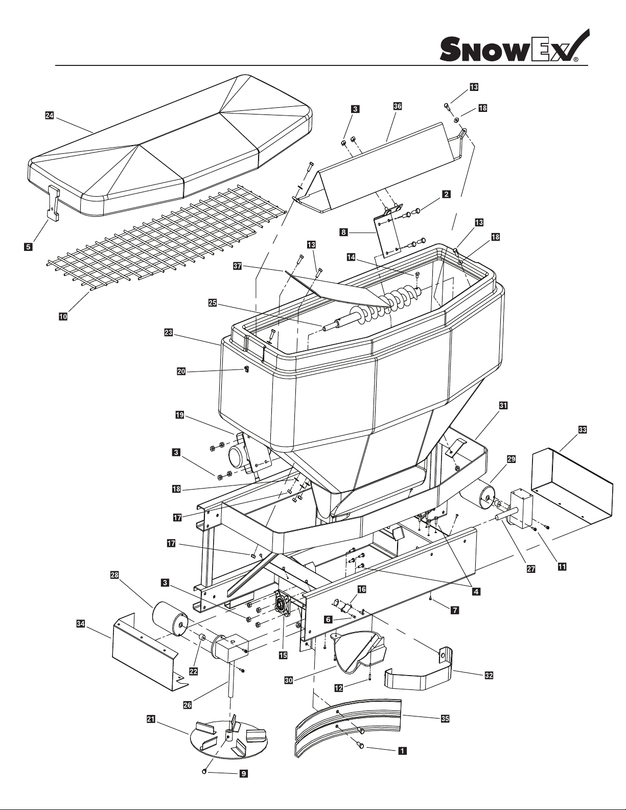
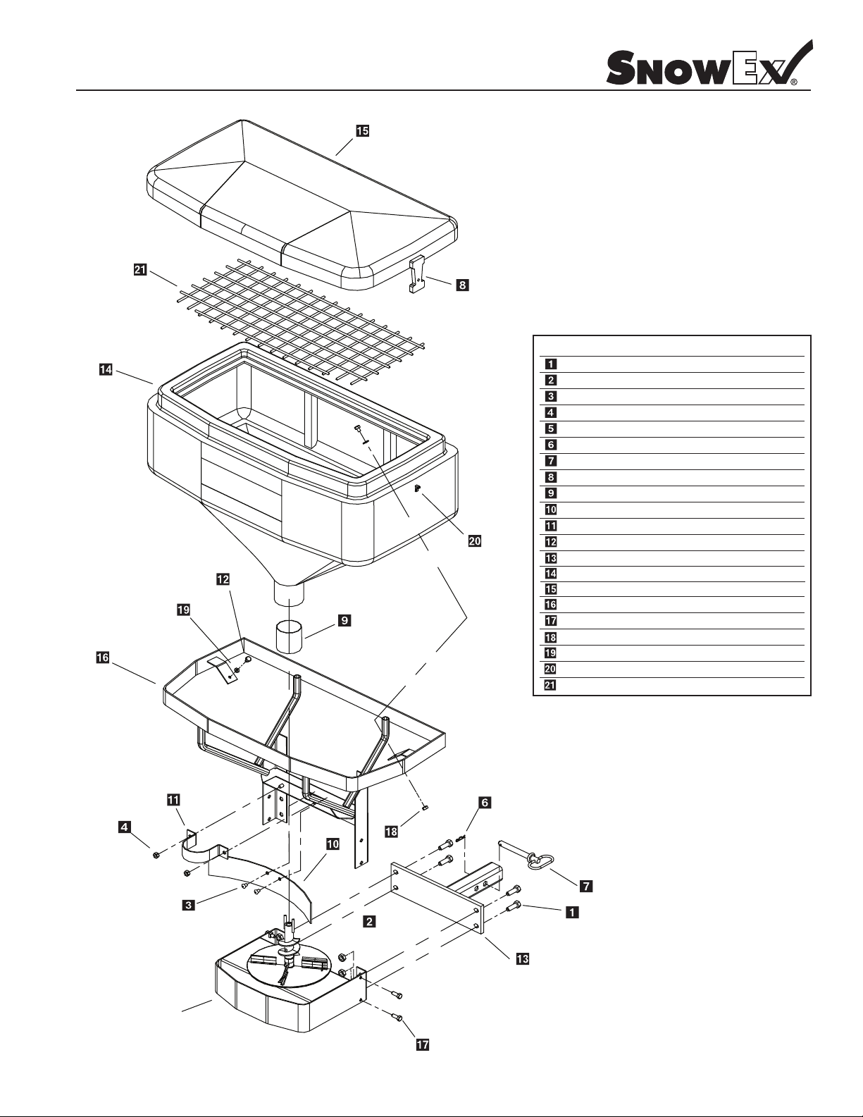
Parts Breakdown
Model #SP-1875
© Trynex International 2009 L1040
7 — 7

Parts Breakdown
Model #SP-1875
Key Part No. Description Qty.
D 6452 3/8-16x1” Ser Flg Bolt 2
D 4122 3/8-16x1-1/2” Hex Bolt 4
D 4124 3/8-16 Lock Nut 8
D 6132 1/4-20 x 3/4 Ser Flg SS 8
D 6105 Flexible Draw Latch 2
D 6877 #8 x 3/4 Driller 2
D 6130 3/16'' Aluminum Rivit 12
D 6337 Inverted V-Mtg Brkt 1
D 6133 5/16-18 x 1/2’’ Hex Bolt 1
D 6334 Top Screen 1
D 6135 10/32 x 5/8’’ Cap Screw 4
D 6333 3/16’’ Rivet, Long 2
D 6137 5/16-18 x 1’’ PH SS Bolt 6
D 6140 5/16-18 x 3/8’’ Set Screw 1
D 6332 Auger Shaft Bearing 1
7 — 8
Key Part No. Description Qty.
D 6501 Auger Transmission 1
Key Part No. Description Qty.
D 6356 Bearing Access Cover 1
D 6394 5/16-18 KEPS Nut 8
D 6169 3/8’’ SS Flat Washer 10
D 6174 DC-80 Vibrator 1
D 6198 Latch Keeper 2
D 6225 12’’ Steel Spinner 1
D 6232 Motor Trans Coupler 2
D 6313 1875 Hopper 1
D 6314 1875 Lid 1
D 6315 Auger 1
D 6317 Spinner Transmission 1
D 6106 Spinner Motor 1
D 6320 Auger Motor 1
D 6331 Chute 1
D 6323 1875 Frame 1
D 6324 Trim Ring 1
D 6325 Auger Mtr Motor Cover 1
D 6326 Spinner Mtr Cover 1
D 6327 Plastic Deector 1
D 6328 Inverted V-Support 1
D 6330 Material Bae 1
© Trynex International 2009 L1040
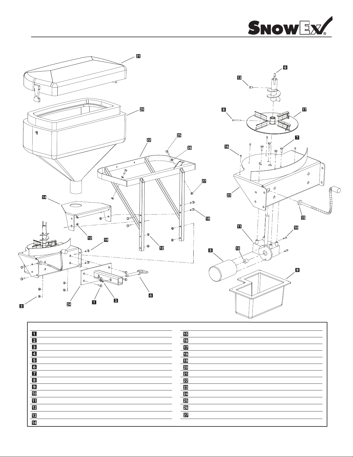
Parts Breakdown
Model #SP-1075
Drive Motor Assy.
See Page 7-11
© Trynex International 2009 L1040
Key
Part No.
D 4115
D 6463
D 6584
D 4124
D 4125
D 6262
D 6263
D 6105
D 6108
D 6110
D 6260
D 6128
D 6129
D 6137
D 6394
D 6452
D 6169
D 6198
D 6261
D 6133
D 5706
Description Qty.
1/2-13 x 1” Hex Bolt (ref. only)
Large Plastic Push Pin
3/8-16 Serrated Flg Nut
3/8-16 Lock Nut
3/8” Flat Washer
1075 Hopper
1075 Lid w/Latches
Flexible Draw Latch
Stainless Throat Liner
Deector 20”
1075 Main Frame
Spinner Guard
Throat Clamp
5/16-18 x 1-1/4 SS Panhead
5/16” Keps Nut
3/8-16 x 1” Ind Hwh Tcs
3/8” SS Washer
Latch Keeper
1075 Top Screen
5/16-18 x 1/2 HHCS
5/16-18 Serrated Flange Nut
2
2
6
2
1
1
2
1
1
1
1
1
2
2
4
2
2
1
4
4
7 — 9
Parts Breakdown
Model #SP-575
Key
Part No.
D 4116
D 4120
D 6463
D 6584
D 4125
D 4135
D 4136
D 6105
D 6108
D 6110
D 6129
D 6137
D 6149
D 6239
D 6240
D 6245
D 6452
D 6168
D 6169
D 6198
D 6257
Description Qty.
1/2-13 x 1-1/2” Hexbolt
1/2-13 Lock Nut
Deector Push Fastener
3/8-16 Serrated Flg Nut
3/8” Flat Washer
2-5/16 Hair Pin Clip
5/8” x 5-1/2” Hitch Pin
Flexible Draw Latch
Stainless Throat Liner
Deector 20”
Throat Clamp
5/16-18 x 1-1/4” SS Panhead
2” Receiver Hitch
575 Hopper
575 Lid W/Latches
575 Main Frame
3/8-16 x 1” Ind Hwh Tcs
5/16” Hex Nut
3/8” SS Washer
Latch Keeper
575 Top Screen
8
4
2
2
2
1
1
2
1
1
1
2
1
1
1
1
4
2
2
2
1
Motor Drive Assembly
See Page 7-11
7 — 10
© Trynex International 2009 L1040
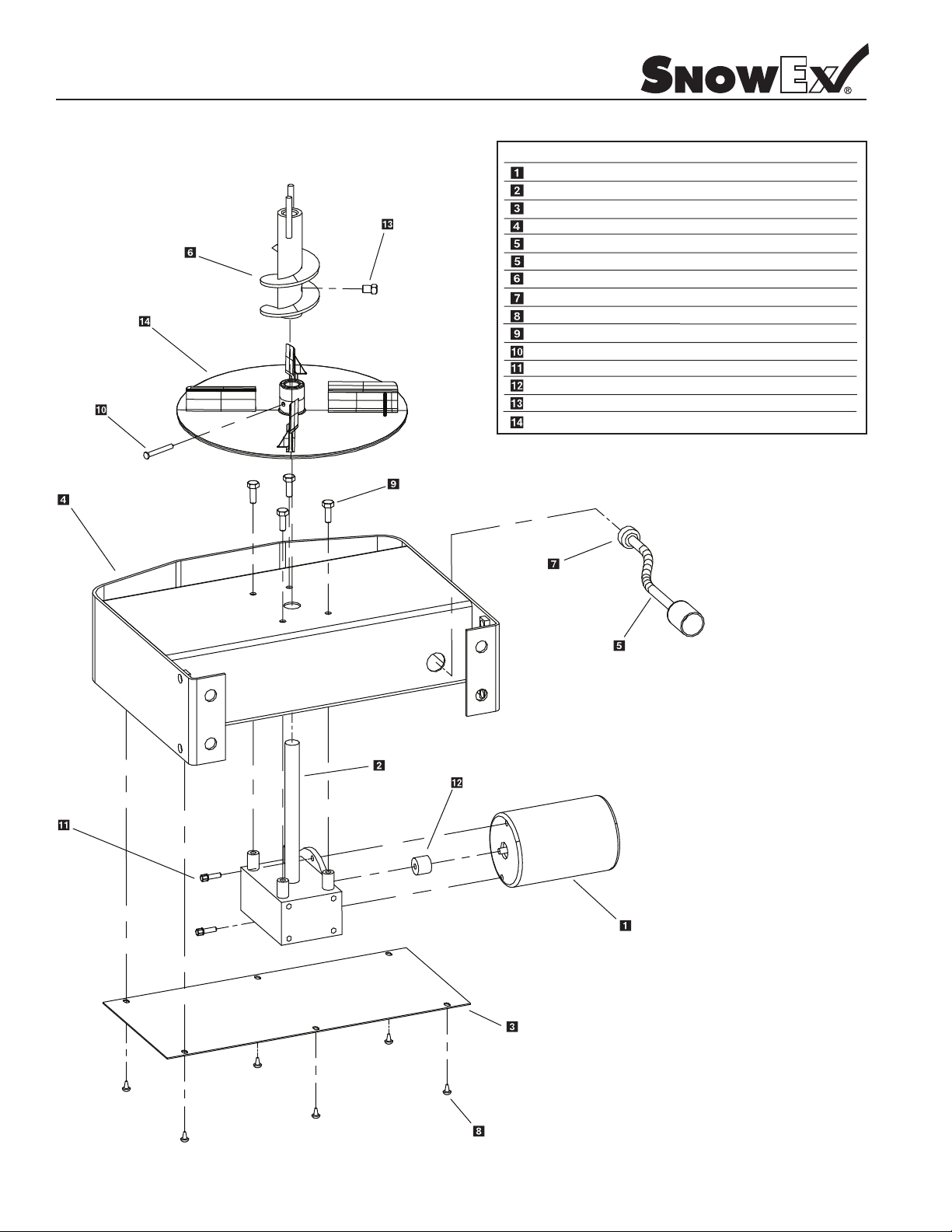
Complete Drive Assembly Parts Breakdown
SP-575 – D6117 SP-1075 – D6175
2000 – Current
Key
Part No.
D 6106
D 6107
D 6109
D 6111
D 6115
D 6162
D 6122
D 6781
D 6467
D 6131
D 6398
D 6122
D 6232
D 6140
D 6750
Description
Motor 12 Volt DC
Transmission
Motor Cover
Drive Enclosure
1075 Power Cord
575 Power Cord
Auger
1/2” NPT Plastic nut
Plastic Push Fastener
1/4”-20 x 1/2” Hex Bolt Stainless
3/16 x 1-1/4” Detent Clevis Pin
#10-32 x 5/8 Serrated Flange Bolt
Motor Drive Coupler
5/16-18 x 3/8” Set Screw
10” Injection Molded Spinner
Qty.
1
1
1
1
1
1
1
1
6
4
1
2
1
1
1
© Trynex International 2009 L1040
7 — 11
Parts Breakdown
Model #SP-325
7 — 12
yeK
.oN traP
D 4116 1/2-13 x 1-1/2” Hex Bolt
D 4120
D 4135
D 4136
D 6106
D 6122
D 6131
D 6398
D 6708
D 6172
D 6715
D 6138
D 6140
D 6702
1/2” Lock Nut
2-5/16” Hair Pin Clip
5/8” x 5-1/2” Pin
12 VDC Motor
Hi-Flow Auger
1/4-20 x 1/2” Serrated Flange SS
3/16” Pin
Plastic Bottom Cover
10-32 x 5/8” Serrated Flange Bolt
14.5:1 Ratio Transmission
5/16 Lock Nut
5/16 -18 x 1/2” Hex Bolt
Hopper Support Plate
4
4
1
1
1
1
4
1
1
2
1
8
1
1
.ytQ noitpircseD
yeK
D 6162
D 6487
D 6750
D 6232
D 6462
D 6475
D 6476
D 6477
D 6480
D 6485
D 6137
.oN traP
24” Power Cord
#8 x 1/2” Hex Head Sheet Screw
10” Plastic Spinner
Motor Drive Coupler
5/16-18 x 1-3/4” HHCS
SP-325 Yellow Hopper
SP-325 Lid Assy
SP-325 Frame Weldment
Trans Mount Weldment
LDM - 175 Lt Duty Rec Mount
5/16-18 X 1-1/4” SS Panhead
3/8” SS Washer
5/16-18 Hex Nut
© Trynex International 2009 L1040
.ytQ noitpircseD
1
5
1
1
8
1
1
1
1
1
2
2D 6169
2 D 6168
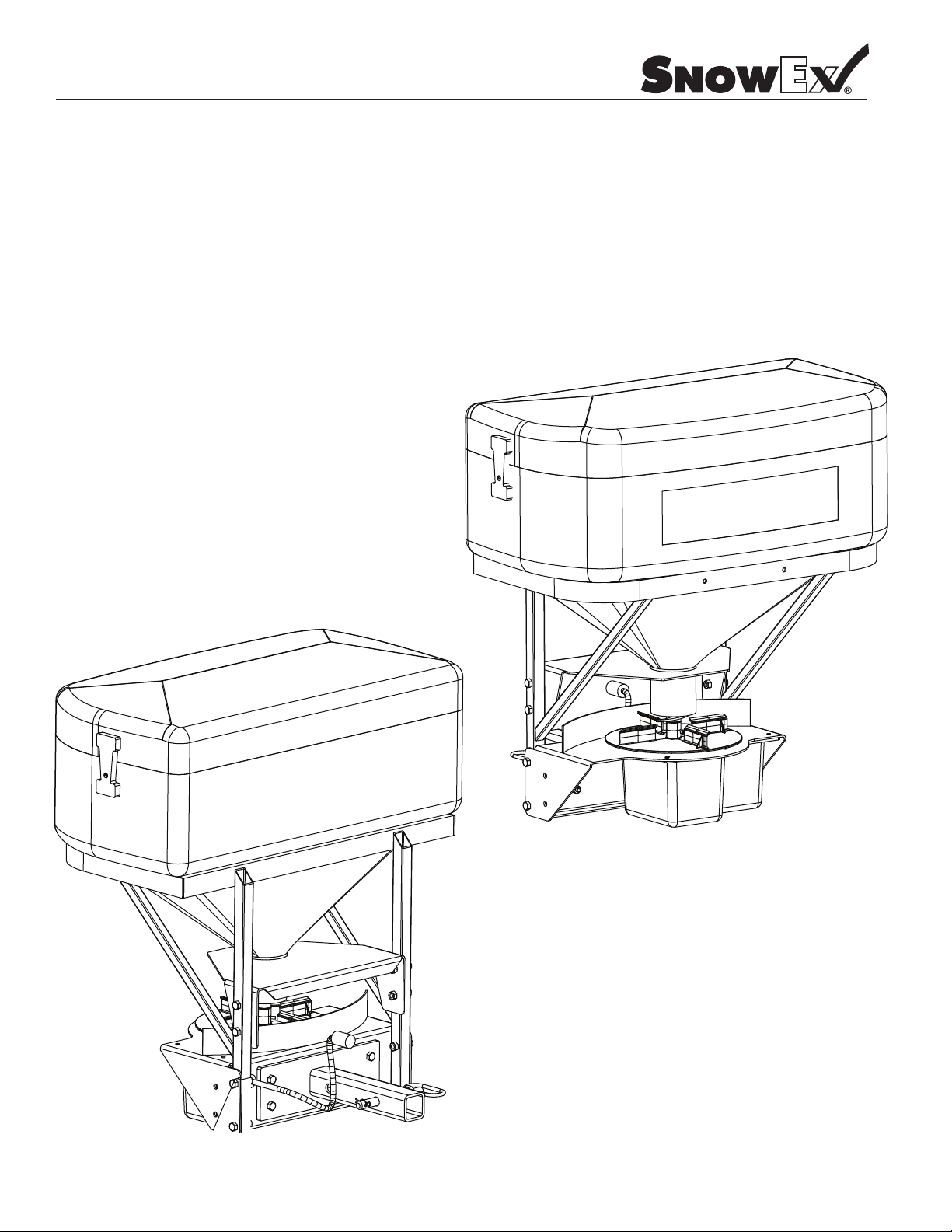
Mounting Instructions
Model #SP-325
Step 1: Install 2" Receiver Mount to Spreader with supplied hardware. (See parts diagram for more detail)
Step 2: Insert Spreader into 2" Vehicle Receiver Hitch. (Use suppled pin with lock to secure Spreader).
Step 3: Connect Spreader power plug to bumper plug.
Step 4: Read operating Instructions before using spreader.
© Trynex International 2009 L1040
7 — 13

General Wiring Instructions
Step 1: Take harness assembly and route from the rear of the vehicle to the front. Route harness along frame and attach to
frame holes and frame supports. It is not recommended to attach to fuel or brake lines for obvious reasons. Do not route
close to exhaust system or engine, even though Snowex uses high temperature wiring, it still could melt under extreme heat and
short the spreader electrical system, as well as the vehicle electrical system.
Mount rear plug on bumper using supplied bolts, locate towards the center of the bumper to reduce the amount of
Step 2:
debris the tires will throw to the rear. Important: Apply a small amount of dielectric grease to the plug. Also try to mount so
plug faces upward to help keep plugs tightly sealed.
Step 3: Secure harness from the rear to the front using heavy duty ty-wraps or frame clips along the frame and lighter duty
ty-wraps everywhere else.
Step 4:
battery yet. Drill a 3/4" hole in the re wall, or use existing access hole, for
and harness through hole. Be sure to check the area on the other side of the re wall to make sure you are not going to drill into the
vehicle harness or a control module. Generally you can drill on either side of the steering wheel for a good location.
Step 5: Connect harness to the back of the controller and mount to a suitable location. NOTE: You may want to contact customer
before mounting controller, some prefer not to have holes drilled into the dashboard. Ty-wrap loose controller harness and move to
the engine compartment. Do not mount close to any heater vents.
Step 6:
system, secure loose loom to any other large or medium vehicle harness with medium duty ty-wraps; this will secure wiring harness.
Step 7:
Layout harness portion that connects to the battery along the re wall and fender well. Do not connect power leads to
the control portion of the harness and route connector
Connect power leads to the battery: Red + Positive, Black – Negative, always connect to the primary battery if using a dual ba
Push the ON/OFF button on the controller to check for power, when that has been conrmed turn power O . The electrical
portion of the installation is complete.
ttery
7 — 14
NOTE: If adding an inline fuse (575 and 1075 only), use a 35 amp slow blow (time delay) or a 35 amp relay.
© Trynex International 2009 L1040
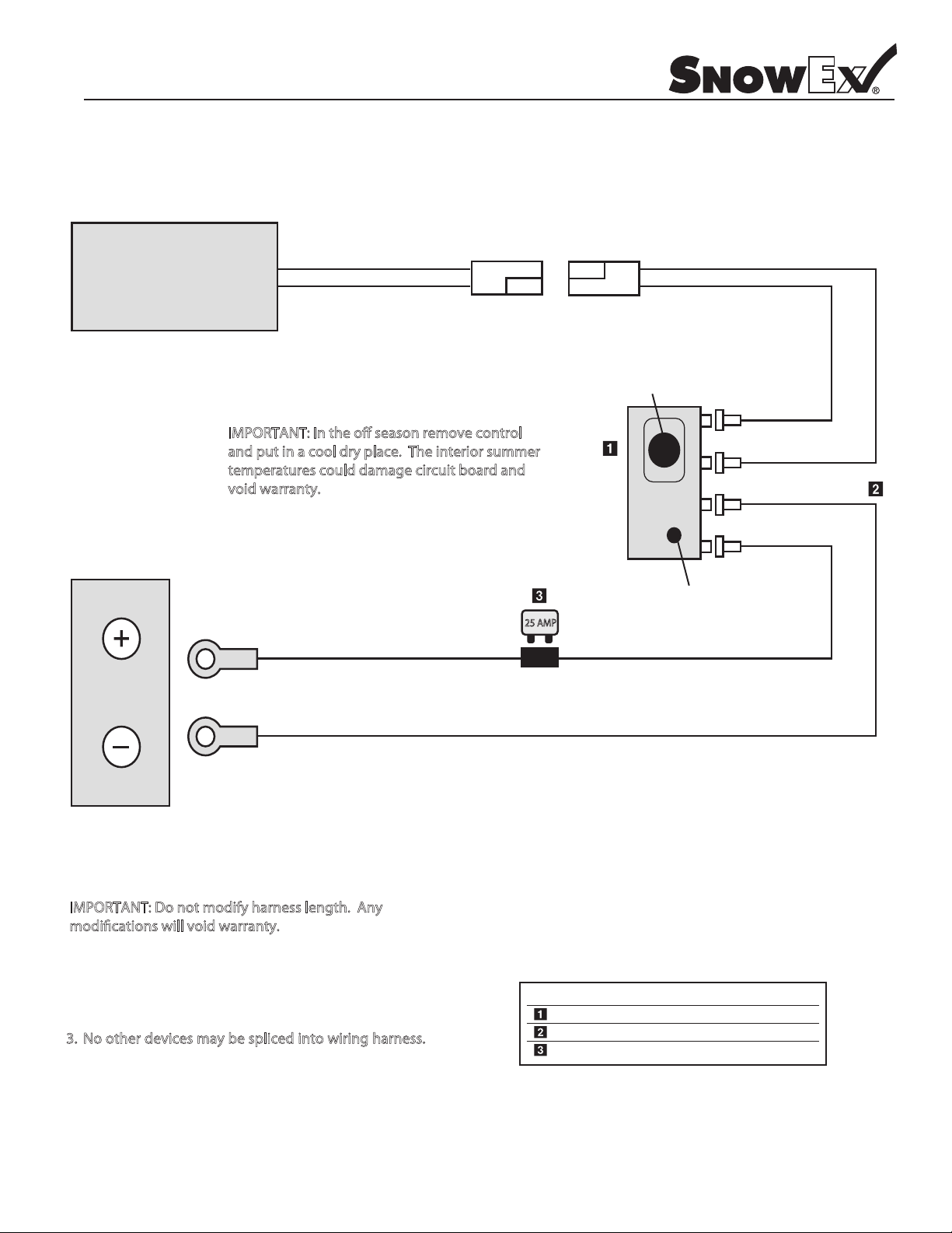
Wiring Diagram
Model # SP-325
SPREADER MOTOR
O o o c l
d c ol d pl c e o
vo d
(–) Neg. Black
(+) Pos.Red
Speed Control Knob
c ld g c c b d d
12 VOLT
BATTERY
(+) Pos.Red
(–) Neg. Black
O o o d f l
d c ll o d
Special Notes:
1. All external connections must have dielectric grease.
2. Read lead labels before attaching to power source or ground.
o o ev p o
4. Any repairs to wiring harness must be done with heat
shrink butt connectors.
On/O Switch
Key Part No. Description Qty.
D 6474 Mini Control 1
D 6486 325 Harness 1
D 6748 25 Amp Breaker 1
© Trynex International 2009 L1040
7 — 15
Control and Harness Diagram
Model # SP-1075/SP-575
Connector
(rubber molded type)
Black Lead (-) Neg
+ POS
Red
- NEG
Black
Red Lead (+) Pos
CONTROL
HARNESS PLUG
SPINNER CIRCUIT
Battery
Anderson
Connector
Anderson Block
(4) Pos
INPUT POWER
Red Positive (+)
M O A ov o
a p a o p o
p a ag bo
vo a a
Red
Positive (+)
Black
Negative (–)
INPUT GROUND
SPINNER OUTPUT POWER
Red Positive (+)
Black Negative (–)
SPINNER OUTPUT GROUND
Black Negative (–)
O o o d f l
d c ll o d
Special Notes:
1. All external connections must have dielectric grease.
2. Read lead labels before attaching to power source or ground.
o o ev p o
4. Any repairs to wiring harness must be done with heat
shrink butt connectors.
5. If inline fuse is installed, use a 35 amp time delay type
or a circuit breaker (575 and 1075).
7 — 16
VEHICLE
BUMPER PLUG
.ytQ noitpircseD .oN traP yeK
D 6114 Wiring Harness - 24’ 1
D 6230 1075/575 Variable Speed Controller 1
2 bonK tekcarB 4216 D
D 6123 Controller Mounting Bracket 1
D 6118 Dust Cover 1
D 6242 3 Terminal Contol Power Switch 1
D 6241 Blast Switch 1
D 6170 Anderson Connector With Leads 1
D 6344 Dielectric Grease - 1 1/2 oz. (not shown) 1
© Trynex International 2009 L1040
 Loading...