

TrynEx International, LLC, 531 Ajax Drive, Madison Heights, MI 48071-2429 • www.snowexproducts.com
July 15, 2018
Lit. No. 70445, Rev. 03
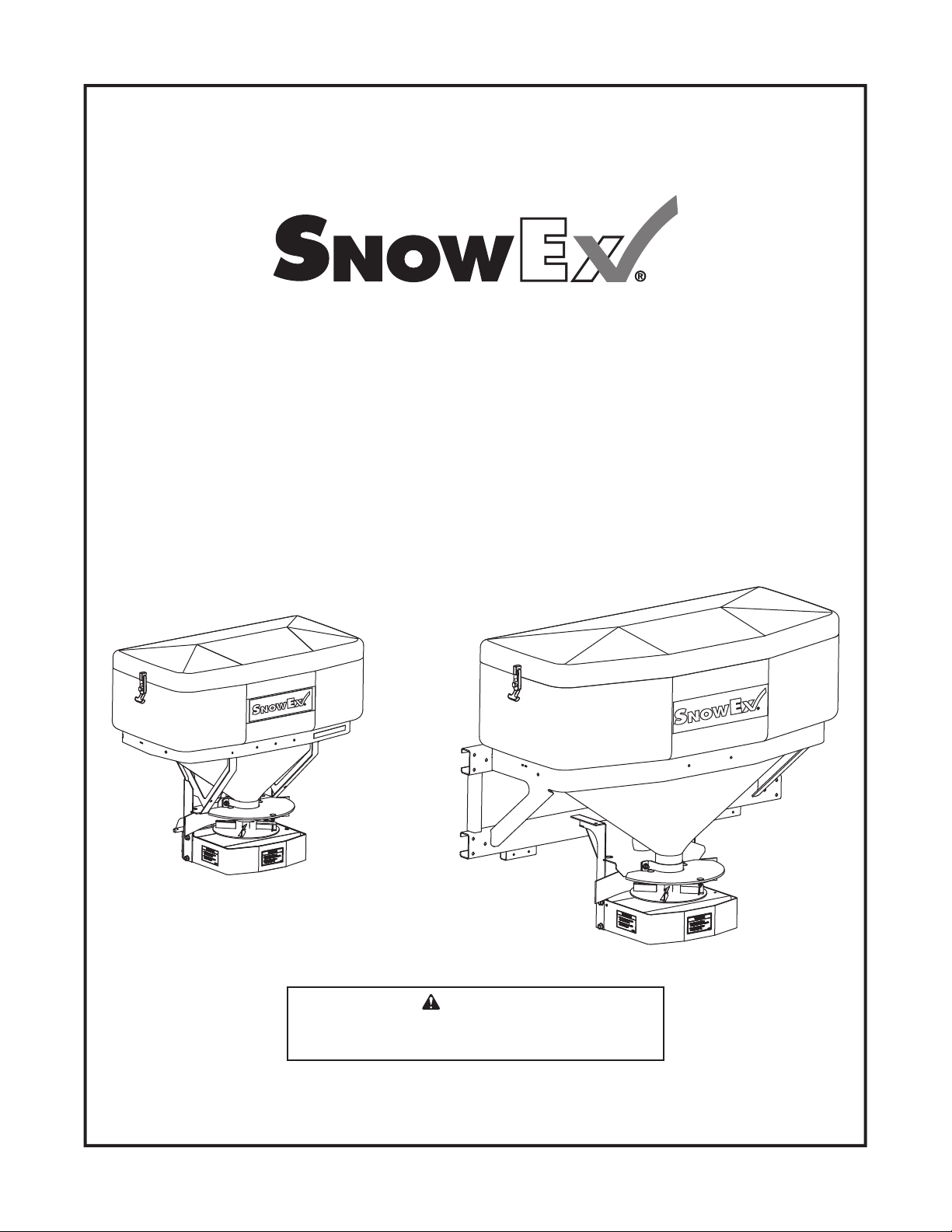
Tailgate Pro 575X, Tailgate Pro 1075X
Single-Stage Tailgate Spreader
SP-575X-1, SP-1075X-1
Owner's Manual
Read this manual before installing or operating
the spreader.
This Owner's Manual is for SnowEx
beginning with 160501 and higher.
This document supersedes all editions with an earlier date.
CAUTION
®
Tailgate Pro spreaders with serial numbers


TABLE OF CONTENTS
INTRODUCTION ......................................................... 4
Owner's Information Form ....................................4
SAFETY ...................................................................... 5
Safety Defi nitions .................................................. 5
Warning/Caution Labels ....................................... 5
Serial Number Label .............................................6
Safety Precautions ................................................ 7
Fuses ....................................................................7
Personal Safety..................................................... 8
Fire and Explosion ................................................ 8
Cell Phones ...........................................................8
Ventilation .............................................................8
Battery Safety ....................................................... 8
Noise ..................................................................... 8
Vibration ................................................................ 8
Spreader Weight ...................................................8
Torque Chart ......................................................... 9
LOADING .................................................................. 10
Certifi cation ......................................................... 10
Approximate Material Weights ............................10
MOUNTING THE SPREADER ................................. 11
Model SP-1075X-1 ............................................. 11
Model SP-575X-1 ................................................ 11
License Plate Installation (if required) ................. 12
OPERATING THE SPREADER ................................ 13
Driving and Spreading on Snow and Ice ............ 13
Powering the Control .......................................... 14
Starting and Stopping Spreader ......................... 14
Controlling Material Application .......................... 15
BLAST/Maximum Application ....................... 15
Cab Control Modes .............................................15
Standby Mode ..............................................15
Ready Mode ................................................. 15
ON Mode ...................................................... 15
Error Mode ................................................... 15
Cab Control Codes ............................................. 16
Setup Codes ................................................. 16
Information Codes ........................................ 16
Error Codes .................................................. 16
Setup Procedures ............................................... 18
Calibrate Empty Hopper Setting ................... 18
Clearing Empty Hopper Calibration Data .....18
Adjust LED Brightness Level ........................18
Spreading Tips .................................................... 19
MAINTENANCE ........................................................20
Lubrication .......................................................... 20
After Each Use .................................................... 20
At the End of Each Season or After
Extended Storage ............................................20
Storage ............................................................... 20
Fuse Replacement .............................................. 20
HARNESS WIRING DIAGRAM ................................ 21
TROUBLESHOOTING GUIDE ................................. 22
Lit. No. 70445, Rev. 03 3 July 15, 2018

INTRODUCTION
OWNER'S INFORMATION
Owner's Name:
______________________________________________________________________
Date Purchased:
_____________________________________________________________________
Distributor Name:
__________________________________________
Phone:
_________________
Distributor Address:
___________________________________________________________________
Vehicle Model:
_____________________________________________
Year:
__________________
Spreader Model:
_________________________
Serial #:
__________________________________
Spreader Weight:
_____________________
lb/kg
This manual has been prepared to acquaint you with
the safety information, operation, and maintenance of
your new tailgate spreader. Please read this manual
carefully and follow all recommendations. This will
help ensure profi table and trouble-free operation of
your tailgate spreader. Keep this manual accessible. It
is a handy reference in case minor service is required.
When service is necessary, bring your spreader to
your distributor. They know the spreader best and are
interested in your complete satisfaction.
NOTE: This spreader is designed to spread snow
and ice control materials only. Do not use it
for purposes other than those specifi ed in this
manual.
OWNER'S INFORMATION
Owner's Name:
______________________________________________________________________
Warranty Registration
Follow the directions on the SnowEx® Warranty
Registration and Customer Survey form included in
the spreader literature kit.
The registration form is also available online at
www.snowexproducts.com. Under "Support" select
"Warranty Registration."
Date Purchased:
Distributor Name:
Distributor Address:
Vehicle Model:
Spreader Model:
Spreader Weight:
_____________________________________________________________________
__________________________________________
_____________________________________________
_________________________
_____________________
Phone:
___________________________________________________________________
Year:
Serial #:
lb/ kg
__________________________________
_________________
__________________
Lit. No. 70445, Rev. 03 4 July 15, 2018
SAFETY
SAFETY DEFINITIONS
WARNING
Indicates a potentially hazardous situation
that, if not avoided, could result in death or
serious personal injury.
CAUTION
Indicates a potentially hazardous situation
that, if not avoided, may result in minor or
moderate injury. It may also be used to alert
against unsafe practices.
NOTE: Indicates a situation or action that can lead
to damage to your spreader and vehicle or other
property. Other useful information can also be
described.
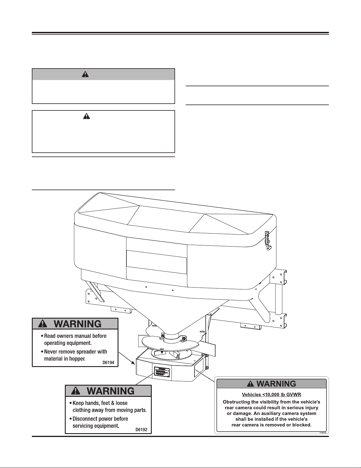
WARNING/CAUTION LABELS
Please become familiar with the warning and caution
labels on the spreader.
NOTE: If labels are missing or cannot be read, see
your sales outlet.
Lit. No. 70445, Rev. 03 5 July 15, 2018
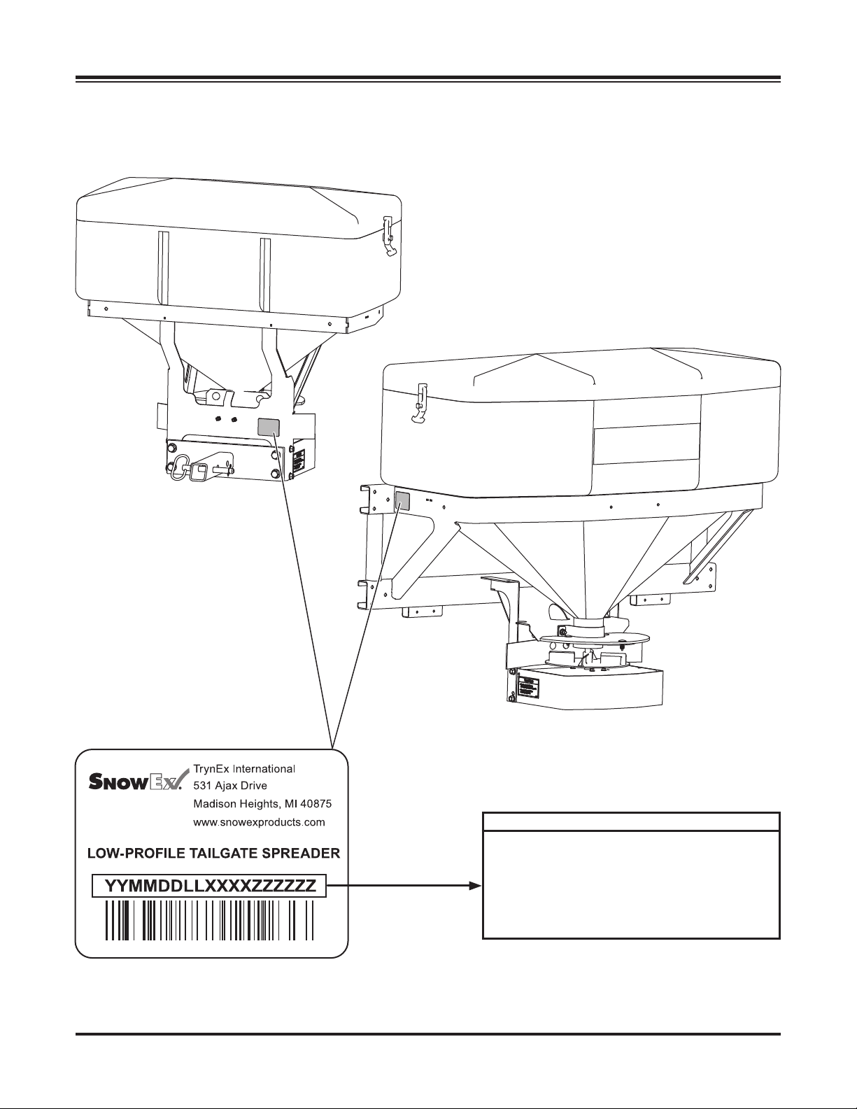
SERIAL NUMBER LABEL
SAFETY
Model SP-575X-1
Model SP-1075X-1
Code Defi nition
YY 2-Digit Year
MM 2-Digit Month
DD 2-Digit Day
LL 2-Digit Location Code
XXXX 4-Digit Sequential Number
ZZZZZZ 5−7-Digit Assembly Part Number
Lit. No. 70445, Rev. 03 6 July 15, 2018

SAFETY
SAFETY PRECAUTIONS
Improper installation and operation could cause
personal injury and/or equipment and property
damage. Read and understand labels and the
Owner's Manual before installing, operating, or making
adjustments.
WARNING
• Driver to keep bystanders minimum of
25 feet away from operating spreader.
• Before working with the spreader, secure all
loose-fi tting clothing and unrestrained hair.
• Before operating the spreader, verify that all
safety guards are in place.
• Before servicing the spreader, wait for
conveyor, auger, and spinner to stop.
• Do not climb into or ride on spreader.
WARNING
Overloading could result in an
accident or damage. Do not exceed
GVWR or GAWR ratings as found on
the driver-side door cornerpost of
the vehicle. See Loading section to determine
maximum volumes of spreading material.
WARNING
Do not install the control for this product in
the deployment path of an air bag. Refer to
vehicle manufacturer's manual for air bag
deployment area(s).
WARNING
Vehicles <10,000 lb GVWR: Obstructing
the visibility from the vehicle's rear camera
could result in serious injury or damage. An
auxiliary camera system shall be installed
if the vehicle's rear camera is removed or
blocked.
CAUTION
If rear directional, CHMSL light, or brake
stoplights are obstructed by the spreader, the
lights shall be relocated, or auxiliary directional
or brake stoplights shall be installed.
CAUTION
• Do not operate a spreader in need of
maintenance.
• Before operating the spreader, reassemble
any parts or hardware removed for cleaning
or adjusting.
• Before operating the spreader, remove
materials such as cleaning rags, brushes,
and hand tools from the spreader.
• Before operating the spreader, read the
engine owner's manual, if so equipped.
• While operating the spreader, use auxiliary
warning lights, except when prohibited by law.
• Tighten all fasteners according to the
Torque Chart. Refer to Torque Chart for the
recommended torque values.
CAUTION
Disconnect electric and/or hydraulic power
and tag out if required before servicing or
performing maintenance.
CAUTION
DO NOT leave unused material in
hopper. Material can freeze or solidify,
causing unit to not work properly.
Empty and clean after each use.
NOTE: Lubricate grease fi ttings after each use.
Use a good quality multipurpose grease.
FUSES
The electrical system contains several
CAUTION
During the hopper spreader installation
we recommend the addition of an OSHA
compliant Backup Alarm. This alarm is
required for OSHA governed employers.
Lit. No. 70445, Rev. 03 7 July 15, 2018
automotive-style fuses. If a problem should occur
and fuse replacement is necessary, the replacement
fuse must be of the same type and amperage rating
as the original. Installing a fuse with a higher rating
can damage the system and could start a fi re. Fuse
Replacement, including fuse ratings and locations, is
located in the Maintenance section of this Owner's
Manual.
SAFETY
PERSONAL SAFETY
• Remove ignition key and put the vehicle in park or
in gear to prevent others from starting the vehicle
during installation or service.
• Wear only snug-fi tting clothing while working on
your vehicle or spreader.
• Do not wear jewelry or a necktie, and secure long hair.
• Wear safety goggles to protect your eyes from
battery acid, gasoline, dirt, and dust.
• Avoid touching hot surfaces such as the engine,
radiator, hoses, and exhaust pipes.
• Always have a fi re extinguisher rated BC handy,
for fl ammable liquids and electrical fi res.
FIRE AND EXPLOSION
WARNING
Gasoline is highly fl ammable and gasoline
vapor is explosive. Never smoke while
working on vehicle. Keep all open fl ames
away from gasoline tank and lines. Wipe up
any spilled gasoline immediately.
VENTILATION
WARNING
Vehicle exhaust contains lethal fumes.
Breathing these fumes, even in low
concentrations, can cause death. Never
operate a vehicle in an enclosed area without
venting exhaust to the outside.
BATTERY SAFETY
CAUTION
Batteries normally produce explosive gases
which can cause personal injury. Therefore,
do not allow fl ames, sparks, or lit tobacco
to come near the battery. When charging or
working near a battery, always cover your
face and protect your eyes, and also provide
ventilation.
• Batteries contain sulfuric acid, which burns
skin, eyes, and clothing.
• Disconnect the battery before removing or
replacing any electrical components.
Be careful when using gasoline. Do not use gasoline
to clean parts. Store only in approved containers away
from sources of heat or fl ame.
CELL PHONES
A driver's fi rst responsibility is the safe operation of
the vehicle. The most important thing you can do
to prevent a crash is to avoid distractions and pay
attention to the road. Wait until it is safe to operate
Mobile Communication Equipment such as cell phones,
text messaging devices, pagers, or two-way radios.
NOISE
Airborne noise emission during use is below 70 dB(A)
for the spreader operator.
VIBRATION
Operating spreader vibration does not exceed 2.5 m/s2
to the hand-arm or 0.5 m/s2 to the whole body.
SPREADER WEIGHT
Tailgate Spreader Description Wt (lb) Wt (kg)
Tailgate Pro 575 – Model SP-575X-1 106 48
Tailgate Pro 1075 – Model SP-1075X-1 141 64
Lit. No. 70445, Rev. 03 8 July 15, 2018

TORQUE CHART
CAUTION
Read instructions before assembling.
Fasteners should be fi nger tight until
instructed to tighten according to the Torque
Chart. Use standard methods and practices
when attaching spreader, including proper
personal protective safety equipment.
Recommended Fastener Torque Chart
Inch Fasteners Grade 5 and Grade 8
Size Size
1/4-20 109 15 4
1/4-28 121 171
5/16-18 150 212
5/16-24 170 240
3/8-16 269 376
3/8-24
7/16 -14
7/16 -20
1/2-13
1/2-20
Tor q u e (ft- lb)
Grade
5
8.4
9.7
17.4
19.2
30.8
35.0
49.4
55.2
75.3
85.0
106.4
120. 0
Grade
11. 9
13.7
24.6
27.3
43.6
49.4
69.8
77.9
8
9/16-12
9/16-18
5/8-11
5/8-18
3/4-10
3/4-16
7/8 - 9
7/8 -14 474 6 69
1-12 704 995
Metric Fasteners Class 8.8 and 10.9
Size Size
M6 x 1.00
M8 x 1.25
M10 x 1.50
M12 x 1.75
M14 x 2.00
M16 x 2.00
M18 x 2.50 318222
Tor q u e (ft- lb)
Class
8.8
7.7
19.5
38.5
67
107
167
These torque values apply to fasteners
except those noted in the instructions.
26.9
53.3
93
148
231
Class
10.9
M20 x 2.5011.1
M22 x 2.50
M24 x 3.00
M27 x 3.00
M30 x 3.50
M33 x 3.50
M36 x 4.00
Tor q u e (ft- lb)
Grade
5
297 420
429 606
644 9091-8
Tor q u e (ft- lb)
Class
8.8
325
428
562
796
1117
1468
1952
SAFETY
Grade
8
Class
10.9
450
613
778
113 9
1545
2101
2701
Lit. No. 70445, Rev. 03 9 July 15, 2018

LOADING
This manual covers vehicles which have been
recommended for carrying the spreader. Please see
your local dealer for proper vehicle applications.
CERTIFICATION
WARNING
New untitled vehicle installation of a spreader
requires National Highway Traffi c Safety
Administration altered vehicle certifi cation
labeling. Installer to verify that struck load of
snow or ice control material does not exceed
GVWR or GAWR rating label and complies
with FMVSS.
APPROXIMATE MATERIAL WEIGHTS
WARNING
Overloading could result in an accident or
damage. Do not exceed GVWR or GAWR
as found on the driver-side cornerpost of
vehicle.
WARNING
Do not overload vehicle. Use chart below
to calculate weight of material. Weights of
material are an average for dry materials.
CAUTION
Never use wet materials or materials with
foreign debris with any of these spreaders.
These units are designed to handle dry, clean,
free fl owing material.
CAUTION
Read and adhere to manufacturer's
ice-control material package
labeling including Material Safety
Data Sheet requirements.
MATERIAL WEIGHTS
Density
Material (lb/ft3)(lb/yd3)(kg/m3)
Salt 80 2160 1282
Sand 100 2700 1602
Material densities are approximate and are based on dry,
loose material. It is the responsibility of the operator to
know the weight of the material to be spread and the vehicle
carrying capacity.
NOTE: If spreader and ice control material loading
is in doubt, weigh vehicle for compliance with
vehicle ratings.
Lit. No. 70445, Rev. 03 10 July 15, 2018

MOUNTING THE SPREADER
CAUTION
During removal or mounting, securely grip
spreader to avoid dropping.
The spreader shall be installed according to
instructions supplied. Your local outlet is trained to
provide this service and service your spreader with
factory original parts.
MODEL SP-1075X-1
Mounts are sold separately for the model SP-1075X-1
spreader. Refer to the instructions packed with the
selected mount.
MODEL SP-575X-1
The model SP-575X-1 spreader ships from the factory
with the 2" receiver hitch standard. See below for
attaching receiver hitch to unit.
1/2" Lock
Washers
Hitch Pin
Hitch Pin
Receiver
Mount
Receiver
Mount
1/2" x 1-1/2"
Cap Screws
Model SP-575X-1
Lit. No. 70445, Rev. 03 11 July 15, 2018

MOUNTING THE SPREADER
LICENSE PLATE INSTALLATION
(If Required)
Install the license plate to the mounting holes in the
frame using two 1/4" x 1/2" machine screws and two
1/4" locknuts.
License Plate Mounting Holes
Model SP-575X-1
Model SP-1075X-1
Lit. No. 70445, Rev. 03 12 July 15, 2018

OPERATING THE SPREADER
DRIVING AND SPREADING ON SNOW
AND ICE
CAUTION
Drinking and then driving or spreading is
very dangerous. Your refl exes, perceptions,
attentiveness, and judgment can be affected
by even a small amount of alcohol. You can
have a serious or even fatal collision if you
drive after drinking. Please do not drink then
drive or spread ice-control materials.
Follow your vehicle owner's manual instructions for
driving in snow and ice conditions. Remember, when
you drive on snow or ice, your wheels will not get good
traction. You cannot accelerate as quickly, turning
is more diffi cult, and you will need longer braking
distance. Wet and hard packed snow or ice offer the
worst tire traction. It is very easy to lose control. You
will have diffi culty accelerating. If you do get moving,
you may have poor steering and diffi cult braking,
which can cause you to slide out of control.
Here are some tips for driving in these conditions:
• Drive defensively.
• Do not drink, then drive or spread ice-control
materials.
• Spread or drive only when you have good visibility
for operating a vehicle.
• If you cannot see well due to snow or icy
conditions, you will need to slow down and keep
more space between you and other vehicles.
• Slow down, especially on higher-speed roads.
Your headlamps can light up only so much road
ahead.
• If you are tired, pull off in a safe place and rest.
• The spreader's size and location reduce driver
visibility to the rear of the vehicle. We recommend
an OSHA compliant backup alarm for all governed
employers.
• Keep your windshield and all glass on your vehicle
clean to see around you.
• Dress properly for the weather. Wear layers of
clothing; as you get warm, you can take off layers.
Lit. No. 70445, Rev. 03 13 July 15, 2018

OPERATING THE SPREADER – CAB CONTROL
WARNING
Never operate equipment when under the
infl uence of alcohol, drugs, or medications that
might alter your judgment and/or reaction time.
WARNING
Never exceed 45 mph (72 km/h) when loaded
spreader is attached to vehicle. Braking
distances may be increased and handling
characteristics may be impaired at speeds
above 45 mph (72 km/h).
WARNING
Never allow children to operate or climb on
equipment.
POWERING THE CONTROL
Power is not applied to the control until the vehicle
ignition is turned to ACC or ON. Once the control
has power it performs a light check and displays the
software version on the status display. The control
then checks for a connected spreader. If no spreader
is detected, the control does the following:
If any button is pressed on the control, it will wake and
check again for spreader connection. If no spreader is
detected, it will act as described above. If a spreader
is detected, it will transition to Ready Mode.
STARTING AND STOPPING SPREADER
WARNING
Before starting the spreader, the driver shall
verify that all bystanders are a minimum of
25 feet away from operating spreader.
To start the spreader, press the ON/OFF button. The
control backlights are illuminated when the vehicle
ignition is ON and the spreader is connected. When
the spreader is ON, the ON/OFF button and inner arc
around the control knob will also illuminate.
To stop the spreader, press the ON/OFF button
again.
The ON/OFF button also operates as an emergency
stop when required.
NOTE: The truck ignition must be ON to start
the spreader.
• nC (no connection) appears on the red status
display for fi ve seconds;
• A single beep;
• Control enters standby mode with no lights
illuminated.
Material Width
Control Knob
(Spinner Speed)
Indicator Lights
(8 per Knob)
Status/Error Code
NOTE: If truck ignition is turned OFF while
spreader is running, the motors will stop.
Accessory
Control Buttons
Display (Red)
ON/OFF Button
& Emergency Stop
BLAST Button
(Maximum Application)
Lit. No. 70445, Rev. 03 14 July 15, 2018

OPERATING THE SPREADER – CAB CONTROL
CONTROLLING MATERIAL APPLICATION
The material application settings can be adjusted
while spreader is ON or OFF. Settings are shown by
the indicator lights around the control knob. When the
spreader is OFF, a single LED will light to show the
current setting. When the spreader is ON, the number
of blue LEDs illuminated will increase/decrease as the
knob is turned clockwise/counterclockwise.
The Material Width knob controls spinner speed.
Turning the knob clockwise will increase the width of
the application area.
Turning the control knob counterclockwise will
decrease the width of the application area.
BLAST/Maximum Application
1. Press and hold the BLAST button when maximum
application area is needed temporarily. The
BLAST button will illuminate while depressed.
2. Release the button when maximum application
settings are no longer needed.
NOTE: Spinner speed reverts to the previous
settings once the BLAST button is released.
CAB CONTROL MODES
Standby Mode
Ready Mode
Vehicle ignition is set to ACC or ON; cab control is OFF.
Control has power. Spreader is detected.
The Material Width control knob can be set to start-up
conditions, but the spinner will not operate until the
cab control is turned ON.
(Accessory lights and vibrator are operational.) The
BLAST function is not operational.
ON Mode
Vehicle ignition is set to ACC or ON; cab control is ON.
Spinner motor will start. All cab control functions
are operational. (Accessory lights and vibrator are
operational.)
During normal spreader operation no control codes are
displayed. Information or setup codes will appear when
relevant. These codes will not stop spreader operation.
Error Mode
When an error condition occurs, spreader operation
will shut down. A two-digit error code will fl ash on the
display and a beep will sound. If there are multiple error
codes, the codes will fl ash in a repeating sequence.
Refer to the Error Codes portion of the
following Cab Control Codes table. Also see the
Troubleshooting Guide section of this manual.
Vehicle ignition is set to ACC or ON; cab control is
OFF. Control has power. No spreader was detected.
No lights are illuminated on the control. Press any
button to wake.
Lit. No. 70445, Rev. 03 15 July 15, 2018
Once the error condition has been resolved, press the
ON/OFF button to clear the error code(s). Press the
ON/OFF button again to resume spreader operation.
The error code will reappear if the error condition
has not been rectifi ed. If the error condition persists,
contact your authorized dealer.
Multiple resets within a short time frame will cause
the hopper module to time out if components are
overheating. The control will display an EF error code.
Accessory work lights and AUX 1 can be used when
an error code is in effect, and will remain in their
current state. The vibrator and AUX 2 will not function.

OPERATING THE SPREADER – CAB CONTROL
CAB CONTROL CODES
Setup Codes
Code Defi nition Procedure
Cb Calibrate the Empty Hopper setting. With control in ON mode, press and hold the left control knob until the
Cb code displays. Calibration cycle is automatic.*
Cc Clear calibration data for Empty Hopper
setting; clear EH code.
LS Set LED brightness level. With control in Ready mode, press and hold left control knob to get
SL Confi rms that LED brightness level has
been reset.
* For full instructions, see the "Setup Procedures" section.
Code Defi nition Response
Ar Auto-reverse sequence is active (auger
only).
dU Not applicable to tailgate spreaders.
Possibly indicates a harness or
module issue.
EH Empty hopper (beep will sound). Check hopper for material.
Lb Low battery. Hopper module is sensing
<10V. (Lb becomes an error code
when module senses <6V.)
Press the right control knob to clear all calibration data during the
calibration cycle.
LS code. Release pressure and turn left control knob to desired
brightness setting. Wait for confi rming SL code to display.*
Information Codes
The spreader will automatically detect and attempt to clear a jam. See
the Operating the Spreader section of this manual.
Contact authorized dealer.
Recalibrate Empty Hopper setting as described above for Cb code.
Refer to the Lb row under "Error Codes" (next page).
Error Codes – Spreader Operation Stopped
Code Defi nition Possible Cause Suggested Solution
bb Bad button. Button is stuck.
Button was pressed while
vehicle ignition was entering
ACC or START mode.
Possible harness issue.
bH Bad hopper. Possible module or control
mismatch.
CE No communication with
spreader module.
CF Control malfunction. Control is overheating.
Table continues on next page.
Lit. No. 70445, Rev. 03 16 July 15, 2018
Loose connection.
Module lost power.
May be a combination of faults.
Inspect control. Free up button.
Do not press any spreader cab control buttons
while the vehicle ignition is being engaged.
Check connections and integrity of vehicle
harness.
Replace control or module. Use only genuine
service parts. Contact authorized dealer.
Confi rm that spreader and control harnesses are
connected to the vehicle harness. Check power
to spreader module, all connections, fuses, and
power studs. Check that port B is plugged into
the module.
Inspect connections at spreader module, hopper
drive motor, and spinner drive motor.

OPERATING THE SPREADER – CAB CONTROL
CAB CONTROL CODES continued
Error Codes – Spreader Operation Stopped – continued
Code Defi nition Possible Cause Suggested Solution
CP Not applicable to tailgate
spreaders. See suggested
solution.
Ct Control is hot. Cab temperature is too high.
EF Excessive drive faults. Too many HO and/or SO
HO Hopper overload –
software trip.
HO . Hopper overload –
hardware trip.
HP Hopper power issue.
No motor present.
Low battery. Hopper
Lb
module is sensing <6V.
nC No connection. Spreader not connected to
OH Overheating. Spreader module is too hot.
OH . Overheating module –
microprocessor.
rS Reset of spreader module. Power loss to module detected
SO Spinner drive overload –
software trip.
SO . Spinner drive overload –
hardware trip.
SP Spinner power issue.
No motor present.
Not applicable to tailgate
spreaders.
Control overheated.
error codes; hopper module
overheating.
Drive system has high current.
Material is jammed.
Auger is damaged.
Hopper drive motor is not
connected.
Possible motor defect.
Bad connection or low battery.
Snowplow or other vehicle
power use may be driving
down voltage.
vehicle harness.
Spreader module malfunction.
Accessories wiring/function
problem.
Drive motor overload.
on startup.
Material jammed in
chute/spinner area.
Spinner shaft is damaged.
Spinner drive motor is not
connected.
Possible motor defect.
Reset the control by pressing the ON/OFF
button. If CP code continues to display, contact
authorized dealer.
Turn spreader OFF and allow control to cool off.
Control times out for 60 seconds.
Ensure that auger and/or spinner are not jammed.
Inspect auger; clear material jam.
Check connections to the auger drive motor
(P–FEED and FEED –N posts on the module and
studs on the motor).
Replace the motor.
Voltage is measured at the hopper module, so
Lb code may indicate cable voltage loss. Check
battery, alternator, and connections.
Connect vehicle and spreader harness.
Check vehicle harness fuse.
Inspect spreader and vehicle harnesses.
Check module.
Allow a cool-off period – 60 seconds or longer.
Check for loose harness connections.
Check accessory connections. Check integrity of
accessory wiring and harness.
Clear jammed material.
Contact authorized dealer.
Reset the control by pressing the ON/OFF button.
Check vehicle harness and battery connection.
Inspect spinner and spinner drive components for
alignment and condition. Check for damage to
bearings, shafts, and sprockets.
Adjust and replace parts as required.
Check connections to the motor (SPIN and GND
posts on the module).
Replace the motor.
Lit. No. 70445, Rev. 03 17 July 15, 2018

OPERATING THE SPREADER – CAB CONTROL
SETUP PROCEDURES
Calibrate the Empty Hopper Setting
(Cb and EH Codes)
Calibrating the empty hopper setting enables the cab
control to alert the operator when the hopper is empty.
Recalibrate the empty hopper setting at the start of
each ice-control season.
1. Ensure that the hopper is empty before beginning
the calibration.
2. Turn the vehicle ignition to ACC or ON. Press
the ON/OFF button on the cab control to turn the
control ON.
3. Press and hold the Material Width knob for
approximately 10 seconds until the Cb code
displays.
4. The calibration cycle will begin. The blue LEDs
around the knob will illuminate in succession until
all eight are lit.
Adjust LED Brightness Level
(SL and LS Codes)
The brightness setting of the cab control lights can be
adjusted from 1 to 16. The factory default setting is 8.
1. Turn the vehicle ignition to ACC or ON. If
necessary, press the cab control ON/OFF button
to turn the control OFF.
2. Press and hold the Material Width knob for
approximately 3 seconds until the LS code is
displayed.
3. Release the knob and turn it clockwise or
counterclockwise to increase/decrease the
brightness level. The light level number will show
in the status display.
4. After selecting the desired brightness level, wait
a few seconds for the SL confi rmation code to
display.
NOTE: A brightness level setting of 12 or higher is
recommended for daylight conditions.
5. When the automatic calibration cycle is complete,
the control will automatically revert to the previous
material application settings.
If the control is turned OFF or loses power during
the calibration cycle, the calibration data will be lost.
Make sure the control is ON and restart the calibration
process at Step 3.
Once the empty hopper setting has been calibrated,
the EH code will fl ash on the display and a beep will
sound whenever the hopper is empty. The EH code is
informational only and will not stop spreader operation.
Clearing Empty Hopper Calibration Data (Cc Code)
The empty hopper calibration may be cleared, if
desired. The control will no longer display the EH
status code when the hopper is empty.
Start the calibration cycle as described above. At
Step 4, press the Material Width knob during the
calibration cycle to clear all calibration data. The Cc
(Clear Calibration) code will display and the control will
exit Cc mode automatically.
Lit. No. 70445, Rev. 03 18 July 15, 2018

OPERATING THE SPREADER
SPREADING TIPS
• Spread ice melters with the storm to prevent
unmanageable levels of ice.
• Never exceed 10 mph (16 km/h) when spreading.
• For a wider pass, increase spinner speed.
• For a heavier pass, drive slower.
• Never operate spreader near pedestrians.
• Calculate spread pattern when near vegetation.
NOTE: The spinner motor is not designed for
continuous duty. Allow the motor to cool between
long cycle times.
Lit. No. 70445, Rev. 03 19 July 15, 2018

MAINTENANCE
WARNING
Never remove the spreader with material in
the hopper.
CAUTION
Disconnect electric power at spreader
electrical wiring harness connection and tag
out if required before servicing or performing
maintenance.
CAUTION
• When replacing parts use only original
manufacturer's parts. Failure to do so will
void warranty.
• The control is a solid-state electronic unit
and is not serviceable. Any attempt to
service will void warranty.
• There are no serviceable parts in the
motor/transmission assembly. Any attempt
to service will void warranty.
• When pressure washing motor enclosure
area, keep spray at least 36" away from
motor enclosures.
AFTER EACH USE
CAUTION
DO NOT leave unused material in
hopper. Material can freeze or solidify,
causing unit to not work properly.
Empty and clean after each use.
• Wash out the hopper and rinse off all external
surfaces.
• Apply dielectric grease on all electrical
connections to prevent corrosion.
AT THE END OF EACH SEASON
OR AFTER EXTENDED STORAGE
• Wash out the hopper and rinse off all external
surfaces.
• Apply dielectric grease on all electrical
connections to prevent corrosion.
• Lubricate all grease fi ttings with good quality
multipurpose grease.
LUBRICATION
To keep your spreader running smoothly, observe the
following recommendations:
• Lubricate bearings after every 20 hours of use.
• Apply a small amount of light oil to latches as
needed.
• Oil or paint all bare metal surfaces.
• If motor cover is removed for any reason, use
silicone sealant to ensure weather proofi ng of
enclosure.
STORAGE
Unplug the cab control from the control harness at the
end of the season, or when the spreader is removed
from the vehicle. Store the spreader and cab control in
a clean, dry location, away from direct sunlight.
FUSE REPLACEMENT
See the Harness Wiring Diagram on the following
page for fuse ratings and locations.
If a problem should occur and fuse replacement is
necessary, the replacement fuse must be of the same
type and amperage rating as the original. Installing a
fuse with a higher rating can damage the system and
could start a fi re.
Lit. No. 70445, Rev. 03 20 July 15, 2018

HARNESS WIRING DIAGRAM
Cab Control
To Vehicle Switched Accessory
To Vehicle CHMSL Signal
(tap located in cab)
10 ga Red
+
Battery
18 ga Red
ORN
40A
Fuse
_
12 ga Black
To Vehicle CHMSL Signal
(tap located in rear of vehicle)
4-Way Connector
Vehicle Control Harness
Connectors
18 ga Shielded
Twisted - Pa i r Ca b l e
10 ga Red
10 ga Black
Vehicle
Cable
Assembly
ORN
To Vehicle Park Light Tap, if License
Plate Light Kit accessory is installed.
3-POST SPREADER MODULE
XXXXX
PN
Accessory Taps
B
To Ve h i cl e C a bl e
Assembly
BRN
Connect to
Spreader Harness
To Spinn e r
Motor
6-Pin
Connector
Lit. No. 70445, Rev. 03 21 July 15, 2018

TROUBLESHOOTING GUIDE
Please see your distributor for service. The troubleshooting reference table below may guide you in diagnosing
the issue.
For a reference table of the cab control error codes, see the "Operating the Spreader – Cab Control" section of
this manual.
Before servicing the spreader:
• Review all safety information.
• Confi rm that all electrical connections are tight and clean.
• Confi rm that nothing is jammed in the hopper.
Problem Possible Cause Suggested Solution
No power to cab control.
Ignition and control switches ON;
control knob indicator lights not
illuminated.
Cab control shuts down.
1. Control is in standby mode.
Spreader is not connected.
2. Control connector plug is loose. 2. Check plug connection at cab control.
3. Switched accessory connection
is poor, or faulty battery.
4. Blown fuse.
5. Vehicle control harness is damaged.
Unplug the spreader harness and tag out, if required,
before performing any of the following repairs.
1. Cross-reference displayed error
code with list on page 16−17.
2. Poor electrical conditions.
1. Press any button on control to wake.
3a. Check for low battery.
3b. Check switched accessory
connection.
4. Replace spreader vehicle battery
cable fuse.
5. Repair or replace damaged wires or
harness as required.
1a. See suggested solution on page 16−17.
1b. Reset the control by pressing the
ON/OFF button.
2a. Clean or replace connectors.
2b. Apply dielectric grease.
3. Electrical short. 3. Check electrical connections.
Unplug the spreader harness and tag out, if required,
Turning control knob does not
change motor speed. Control is
powered ON.
Spreader does not operate.
Lit. No. 70445, Rev. 03 22 July 15, 2018
1. Malfunctioning cab control. 1. Replace cab control.
2. Malfunctioning motor. 2. Replace motor.
3. Malfunctioning spreader module. 3. Replace spreader module.
1. Wire harness is damaged or has an
open circuit between cab control
and spreader.
2. Overloaded condition has triggered
a time-out, or damaged motor or
module.
before performing any of the following repairs.
Unplug the spreader harness and tag out, if required,
before performing any of the following repairs.
1a. Check plug connections at cab
control and spreader.
1b. Check wire connections at vehicle
battery and fuse.
1c. Check motor connections.
2a. Wait 60 seconds for time-out to
expire.
2b. Check motor. Repair or replace.
2c. Replace module.

Problem Possible Cause Suggested Solution
Motor does not run.
TROUBLESHOOTING GUIDE
Unplug the spreader harness and tag out, if required,
before performing any of the following repairs.
1. Electrical connections are loose.
2. Blown fuse.
3. Motor seizes. 3. Replace motor.
Unplug the spreader harness and tag out, if required,
before performing any of the following repairs.
1. Obstruction in hopper. 1. Clear obstruction.
2. Material bridged. 2. Clear the bridged material.
1. Open access cover and check motor,
harness, and module connections.
2. Replace spreader vehicle battery
cable fuse.
Material does not fl ow.
3. Material is wet. 3. Replace with dry material.
4. Material is coarse or frozen. 4. Replace material.
5a. Check for material jam and clear.
5b. Manually turn spinner and check for
5. Spinner does not turn.
obstruction.
5c. Check connection inside the motor
enclosure.
Lit. No. 70445, Rev. 03 23 July 15, 2018

Tr y nE x Inter nat i ona l
531 Ajax Drive
Madison Heights, MI 48071-2429
www.snowexproducts.com
A DIVISION OF DOUGLAS DYNAMICS, LLC
This product conforms to EU Machinery Directive 2006/42/EC and Directive 2011/65/EC, 2015/863 (RoHS2).
Copyright © 2018 Douglas Dynamics, LLC. All rights reserved. This material may not be reproduced or copied, in whole or in part, in
any printed, mechanical, electronic, fi lm, or other distribution and storage media, without the written consent of TrynEx International, LLC.
Authorization to photocopy items for internal or personal use by TrynEx International outlets or spreader owner is granted.
TrynEx International reserves the right under its product improvement policy to change construction or design details and furnish equipment
when so altered without reference to illustrations or specifi cations used. TrynEx International or the vehicle manufacturer may require or
recommend optional equipment for spreaders. Do not exceed vehicle ratings with a spreader. Patent pending. TrynEx International offers a
limited warranty for all spreaders and accessories. See separately printed page for this important information. The following is a registered (®)
trademark of Douglas Dynamics, LLC: SnowEx®.
Printed in U.S.A.
Lit. No. 70445, Rev. 03 July 15, 2018
 Loading...