

Lit. No. 75312, Rev. 01
SP-100-1 & SP-125-1
Tailgate Spreader
Owner's Manual and Installation Instructions
Original Instructions
July 1, 2018
CAUTION
Read this manual before installing or
operating the spreader.
This manual is for SnowEx® SP-10 0-1 & S P-125-1 tailgate spreader s
with serial numbers beginning with 170109 and higher.
This document supersedes all editions with an earlier date.


TABLE OF CONTENTS
INTRODUCTION ......................................................... 4
Owner's Information Form ....................................4
SAFETY ...................................................................... 5
LOADING .................................................................... 9
Certifi cation ........................................................... 9
Approximate Material Weights .............................. 9
MOUNTING THE SPREADER ................................. 10
Assembly Instructions ......................................... 10
Receiver Mount Spreader ................................... 11
CONTROL AND HARNESS DIAGRAM – MODEL
SP-100-1 ................................................................ 12
Wiring Instructions .............................................. 12
Wiring Diagram: Model SP-100-1 ....................... 13
Harness Diagrams: Model SP-100-1 .................. 14
ELECTRICAL DIAGRAM – MODEL 125-1 .............. 16
Wiring Diagram: Model SP-125-1 ....................... 16
Wiring Instructions for Model SP-125-1 .............. 16
OPERATING THE SPREADER ................................ 17
Driving and Spreading on Snow and Ice ............ 17
Spreading Tips .................................................... 17
REMOVING THE SPREADER ................................. 18
MAINTENANCE ........................................................ 19
Lubrication .......................................................... 19
After Each Use .................................................... 19
At the End of Each Season or
After Extended Storage ................................... 19
Storage ............................................................... 19
TROUBLESHOOTING .............................................. 20
Lit. No. 75312, Rev. 01 3 July 1, 2018

INTRODUCTION
This manual has been prepared to acquaint you with
the safety information, operation, and maintenance of
your new tailgate spreader. Please read this manual
carefully and follow all recommendations. This will
help ensure profi table and trouble-free operation of
your tailgate spreader. Keep this manual accessible. It
is a handy reference in case minor service is required.
When service is necessary, bring your spreader to
your distributor. They know your spreader best and are
interested in your complete satisfaction.
NOTE: This spreader is designed to spread snow
and ice control materials only. Do not use it
for purposes other than those specifi ed in this
manual.
Warranty Registration
Follow the directions on the SnowEx® Warranty
Registration and Customer Survey form included in
the spreader literature kit.
The registration form is also available online at
www.snowexproducts.com. Under "Support" select
"Warranty Registration."
OWNER'S INFORMATION
Owner's Name: ______________________________________________________________________
Date Purchased: _____________________________________________________________________
Distributor Name: __________________________________________ Phone: _________________
Distributor Address: ___________________________________________________________________
Vehicle Model: _____________________________________________ Year: __________________
Spreader Model: _________________________ Serial #: __________________________________
Spreader Weight: _____________________lb/kg
Lit. No. 75312, Rev. 01 4 July 1, 2018

SAFETY
SAFETY DEFINITIONS
WARNING
Indicates a potentially hazardous situation
that, if not avoided, could result in death or
serious personal injury.
CAUTION
Indicates a potentially hazardous situation
that, if not avoided, may result in minor or
moderate injury. It may also be used to alert
against unsafe practices.
NOTE: Indicates a situation or action that can lead
to damage to your spreader and vehicle or other
property. Other useful information can also be
described.
WARNING/CAUTION LABELS
Please become familiar with the warning and caution
labels on the spreader.
NOTE: If labels are missing or cannot be read, see
your sales outlet.
Lit. No. 75312, Rev. 01 5 July 1, 2018
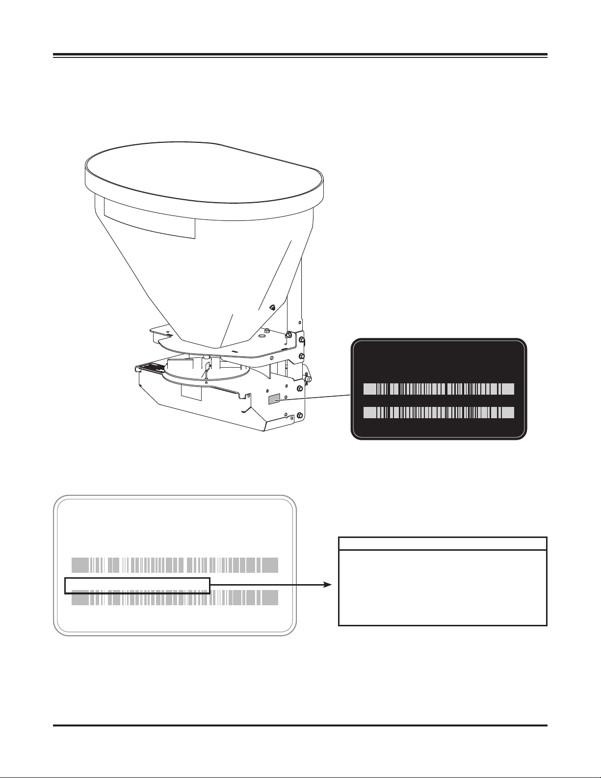
SERIAL NUMBER LABEL
SAFETY
Model No. 00000
Serial No. YYMMDDLLXXXXZZZZZZ
Model No. 00000
Serial No. 000000000000000000
Code Defi nition
YY 2-Digit Year
MM 2-Digit Month
DD 2-Digit Day
LL 2-Digit Location Code
XXXX 4-Digit Sequential Number
ZZZZZZ Assembly Part Number
Lit. No. 75312, Rev. 01 6 July 1, 2018
SAFETY
SAFETY PRECAUTIONS
Improper installation and operation could cause
personal injury and/or equipment and property
damage. Read and understand labels and the
Owner's Manual before installing, operating, or making
adjustments.
WARNING
• Driver to keep bystanders minimum of
25 feet away from operating spreader.
• Before working with the spreader, secure all
loose-fi tting clothing and unrestrained hair.
• Before operating the spreader, verify that all
safety guards are in place.
• Before servicing the spreader, wait for
auger and spinner to stop.
• Do not climb into or ride on spreader.
WARNING
Overloading could result in an
accident or damage. Do not exceed
GVWR or GAWR ratings as found on
the driver-side door cornerpost of
the vehicle. See Loading section to determine
maximum volumes of spreading material.
CAUTION
• Do not operate a spreader in need of
maintenance.
• Before operating the spreader, reassemble
any parts or hardware removed for cleaning
or adjusting.
• Before operating the spreader, remove
materials such as cleaning rags, brushes,
and hand tools from the spreader.
• While operating the spreader, use auxiliary
warning lights, except when prohibited by law.
• Tighten all fasteners according to the
Torque Chart. Refer to Torque Chart for the
recommended torque values.
CAUTION
Disconnect electric and/or hydraulic power
and tag out if required before servicing or
performing maintenance.
CAUTION
DO NOT leave unused material in
hopper. Material can freeze or solidify,
causing unit to not work properly.
Empty and clean after each use.
WARNING
Vehicles <10,000 lb GVWR: Obstructing
the visibility from the vehicle's rear camera
could result in serious injury or damage. An
auxiliary camera system shall be installed
if the vehicle's rear camera is removed or
blocked.
CAUTION
If rear directional, CHMSL light, or brake
stoplights are obstructed by the spreader,
the lights shall be relocated, or auxiliary
directional or brake stoplights shall be
installed.
CAUTION
During the hopper spreader installation
we recommend the addition of an OSHA
compliant Backup Alarm. This alarm is
required for OSHA governed employers.
NOTE: Lubricate grease fi ttings after each use.
Use a good quality multipurpose grease.
PERSONAL SAFETY
• Remove ignition key and put the vehicle in PARK
or in gear to prevent others from starting the
vehicle during installation or service.
• Wear only snug-fi tting clothing while working on
your vehicle or spreader.
• Do not wear jewelry or a necktie, and secure long
hair.
• Wear safety goggles to protect your eyes from
battery acid, gasoline, dirt, and dust.
• Avoid touching hot surfaces such as the engine,
radiator, hoses, and exhaust pipes.
• Always have a fi re extinguisher rated BC handy,
for fl ammable liquids and electrical fi res.
Lit. No. 75312, Rev. 01 7 July 1, 2018

SAFETY
FIRE AND EXPLOSION
WARNING
Gasoline is highly fl ammable and gasoline
vapor is explosive. Never smoke while
working on vehicle. Keep all open fl ames
away from gasoline tank and lines. Wipe up
any spilled gasoline immediately.
Be careful when using gasoline. Do not use gasoline
to clean parts. Store only in approved containers away
from sources of heat or fl ame.
CELL PHONES
A driver's fi rst responsibility is the safe operation of
the vehicle. The most important thing you can do
to prevent a crash is to avoid distractions and pay
attention to the road. Wait until it is safe to operate
Mobile Communication Equipment such as cell phones,
text messaging devices, pagers, or two-way radios.
VENTILATION
WARNING
Vehicle exhaust contains lethal fumes.
Breathing these fumes, even in low
concentrations, can cause death. Never
operate a vehicle in an enclosed area without
venting exhaust to the outside.
BATTERY SAFETY
CAUTION
Batteries normally produce explosive gases
which can cause personal injury. Therefore,
do not allow fl ames, sparks, or lit tobacco
to come near the battery. When charging or
working near a battery, always cover your
face and protect your eyes, and also provide
ventilation.
• Batteries contain sulfuric acid which burns
skin, eyes, and clothing.
• Disconnect the battery before removing or
replacing any electrical components.
NOISE
Airborne noise emission during use is below 70 dB(A)
for the spreader operator.
VIBRATION
Operating snowplow vibration does not exceed
2.5 m/s2 to the hand-arm or 0.5 m/s2 to the whole
body.
TORQUE CHART
CAUTION
Read instructions before assembling.
Fasteners should be fi nger tight until
instructed to tighten according to torque
chart. Use standard methods and practices
when attaching spreader including proper
personal protective safety equipment.
Recommended Fastener Torque Chart
Inch Fasteners Grade 5 and Grade 8
Size Size
1/4-20 109 154
1/4-28 121 171
5/16-18 150 212
5/16-24 170 240
3/8-16 269 376
3/8-24
7/16 -14
7/16 -20
1/2-13
1/2-20
Tor q u e (ft- lb)
Grade
5
8.4
9.7
17.4
19.2
30.8
35.0
49.4
55.2
75.3
85.0
106.4
120. 0
Grade
11. 9
13.7
24.6
27.3
43.6
49.4
69.8
77.9
8
9/16-12
9/16-18
5/8-11
5/8-18
3/4-10
3/4-16
7/8 - 9
7/8 -14 474 66 9
1-12 704 995
Metric Fasteners Class 8.8 and 10.9
Size Size
M6 x 1.00
M8 x 1.25
M10 x 1.50
M12 x 1.75
M14 x 2.00
M16 x 2.00
M18 x 2.50 318222
Tor q u e (ft- lb)
Class
8.8
7.7
19.5
38.5
67
107
167
These torque values apply to fasteners
except those noted in the instructions.
Class
26.9
53.3
93
148
231
10.9
M20 x 2.5011.1
M22 x 2.50
M24 x 3.00
M27 x 3.00
M30 x 3.50
M33 x 3.50
M36 x 4.00
Tor q u e (ft- lb)
Grade
5
297 420
429 60 6
644 9091-8
Tor q u e (ft- lb)
Class
8.8
325
428
562
796
1117
1468
1952
450
613
778
113 9
1545
2101
2701
Grade
8
Class
10.9
Lit. No. 75312, Rev. 01 8 July 1, 2018

LOADING
This manual covers vehicles which have been
recommended for carrying the spreader. Please see
your local dealer for proper vehicle applications.
CERTIFICATION
WARNING
New untitled vehicle installation of a spreader
requires National Highway Traffi c Safety
Administration altered vehicle certifi cation
labeling. Installer to verify that struck load of
snow or ice control material does not exceed
GVWR or GAWR rating label and complies
with FMVSS.
MATERIAL WEIGHTS
WARNING
Overloading could result in an accident or
damage. Do not exceed GVWR or GAWR
as found on the driver-side cornerpost of
vehicle.
WARNING
Do not overload vehicle. Use chart below
to calculate weight of material. Weights of
material are an average for dry materials.
CAUTION
Never use wet materials or materials with
foreign debris with any of these spreaders.
These units are designed to handle dry, clean,
free fl owing material.
CAUTION
Read and adhere to manufacturer's
ice-control material package
labeling including Material Safety
Data Sheet requirements.
Density
Material (lb/ft3)(lb/yd3)(kg/m3)
Salt 80 2160 1282
Sand 100 2700 1602
Material densities are approximate and are based on dry,
loose material. It is the responsibility of the operator to
know the weight of the material to be spread and the vehicle
carrying capacity.
Weight of spreader and mount must be added to
struck material weight to determine total spreader
weight. Do not exceed maximum material capacity
as shown on the safety label (see Safety section).
Use only bagged rock salt with the spreader.
Other forms of spreading material are not
compatible with the tailgate spreader.
NOTE: If spreader and ice control material loading
is in doubt, weigh vehicle for compliance with
vehicle ratings.
Lit. No. 75312, Rev. 01 9 July 1, 2018

MOUNTING THE SPREADER
ASSEMBLY INSTRUCTIONS
The spreader shall be installed according to
instructions supplied. Your local outlet is trained to
provide this service and service your spreader with
factory original parts.
1. Place the drive assembly on a fl at, level surface.
Attach the receiver mount to the drive assembly
as shown below using four 1/2" x 1-1/2" cap
screws. Tighten the fasteners according to the
torque chart.
Drive Assembly
1/2" x 1-1/2"
Receiver Mount
Cap Screw
Support Frame
5/16" Locknuts
5/16" x 1" Cap Screws
3. Mount the throat support to the support frame at
the two lower holes by using the four supplied
5/16" x 1" cap screws and 5/16" locknuts. Tighten
the fasteners according to the torque chart.
2. Mount the support frame to the drive assembly
using the six supplied 5/16" x 1" cap screws and
the four supplied 5/16" locknuts. Tighten the
fasteners according to the torque chart.
5/16"
Locknuts
Lit. No. 75312, Rev. 01 10 July 1, 2018
Throat Support
Support
Frame
5/16" x 1"
Cap Screws

MOUNTING THE SPREADER
CAUTION
Before drilling holes, check to be sure that no
vehicle wiring or other components could be
damaged.
4. Drill four holes in the hopper using the
support frame holes as a template. Place the
backing plate inside the hopper.
5. Fasten the hopper to the support frame by running
the four supplied 5/16" x 1" cap screws through
the backing plate, hopper, and support frame from
inside the hopper. Attach using the four supplied
5/16" locknuts. Tighten the fasteners according to
the torque chart.
RECEIVER MOUNT SPREADER
CAUTION
During removal or mounting, securely grip
spreader to avoid dropping.
The spreader shall be installed according to
instructions supplied. Your local outlet is trained to
provide this service and service your spreader with
factory original parts.
Insert the assembled unit into the receiver hitch and
secure with the supplied hitch pin and hairpin cotter.
Receiver Hitch
Hairpin Cotter
Receiver Mount
Hopper
5/16"
Locknut
5/16" x 1"
Cap Screw
Hitch Pin
Lit. No. 75312, Rev. 01 11 July 1, 2018

CONTROL AND HARNESS DIAGRAM – MODEL SP-100-1
WIRING INSTRUCTIONS
1. Mount the rear plug bracket on the back of the
vehicle. Locate the harness toward the center of
the bumper as it will reduce the amount of debris
getting onto the plug. Apply dielectric grease to
the plug.
2. Route the wires from the back to front using zipties or clamps (not supplied). Do not secure to
brake lines, fuel lines, or near exhaust, engine, or
moving parts. Use the heavy-duty zip-ties along
the frame and lighter duty zip-ties everywhere
else.
CAUTION
Before drilling holes, check to be sure that no
vehicle wiring or other components could be
damaged.
3. Drill a 3/4" hole in the fi rewall near the steering
column. Be sure to check for wires and
components in the way (both sides of the fi rewall)
before drilling the hole.
CAUTION
Do not alter, modify, or install additional
components in shaded areas shown below.
Failure to comply may interfere with airbag
deployment or cause injury to operator in an
accident.
4. Run the data cable into the cab. Zip-tie the wire
under the dash so that it does not get in the way
of the brake or accelerator pedal. Leave enough
of the data cable outside of the dash so that the
operator can hold the control pendant in hand.
Install the pendant mounting base and bracket.
Stick the hook/loop fastener to the pendant and
pendant base.
5. Connect the harness to the back of the control.
Zip-tie loose control harness and move to the
engine compartment. Do not mount close to any
heater vents.
6. Connect power leads to the battery:
Red: POSITIVE (+)
Black: NEGATIVE (–)
Always connect to the primary battery if using
a dual battery system. Secure loose loom to
any other large or medium vehicle harness with
medium-duty zip-ties to secure the wiring harness.
7. Push the ON/OFF button on the control to check
for power. When confi rmed, turn power OFF. The
electrical portion of the installation is complete.
Lit. No. 75312, Rev. 01 12 July 1, 2018

CONTROL AND HARNESS DIAGRAM – MODEL SP-100-1
WIRING DIAGRAM: MODEL SP-100-1
Switch Assembly
IMPORTANT: Do not modify harness length. Any
modifi cations will void warranty.
Control Power Cable
Spreader Control
Vehicle Harness
1. All external connections must have dielectric grease.
2. Read lead labels before attaching to power source
or ground.
3. No other devices may be spliced into wiring harness.
4. Any repairs to wiring harness must be done with
heat shrink butt connectors.
Spreader Harness
1"
Load View
4-Way Connector
43"
33"
38"
Spreader Harness
9"
A
B
Load View
Black
Red Blue
Lit. No. 75312, Rev. 01 13 July 1, 2018
Green
Black Pos. A
Red Pos. B

CONTROL AND HARNESS DIAGRAM – MODEL SP-100-1
HARNESS DIAGRAMS: MODEL SP-100-1
Vehicle Harness
189" ± 3"
Label M (–)
Black
Red
Orange
Blue
Battery Harness
Label "B (+)"
Label M (+)
144"
6"
2"
Label "B (–)"
3"
Lit. No. 75312, Rev. 01 14 July 1, 2018

CONTROL AND HARNESS DIAGRAM – MODEL SP-100-1
HARNESS DIAGRAMS: MODEL SP-100-1
Control
Gate Switch
ON/OFF
Switch Assembly
Spreader Power
ON/OFF
Switch Circuts are:
Left – On
Middle – None
Right – On
Key Way
Key Way
Red
Spinner Speed
ON/OFF
Key Way on this End
Black
Black
Red
Black
Load View
Black
Red
Red
Red
Black
Red
Black
Lit. No. 75312, Rev. 01 15 July 1, 2018

ELECTRICAL DIAGRAM – MODEL SP-125-1
WIRING DIAGRAM: MODEL SP-125-1
Battery
Rubber
Switch
Boot
3/8"
Termina l
Ring
Wiring Harness
25A
Breaker
A
25
ON/OFF
Switch
Fuse Holder
Double Female
3" Jumper
Remove jumper for use
with VAR-020 Variable
Speed Control Kit
IMPORTANT: In the off-season, remove the control
and store in a cool, dry place. The interior summer
temperatures could damage the circuit board and
void the warranty.
Wiring Instructions for Model SP-125-1
1. Install switch at desired location.
2. Run the spreader/vehicle harness from the rear of
the vehicle to the switch area. Attach the female
spade red wire to the switch. Leave the black wire
for Step 5.
3. Route the power harness from the battery to the
switch/control.
4. Attach the red lead to the POSITIVE (+) side of the
battery and the black lead to the NEGATIVE (–)
side of the battery.
5. Attach the female spade red wire on the switch
terminal. Using 3" double female black wire
jumper, attach the black wire from the power
harness to the black wire of the vehicle harness.
6. Install the rubber weatherproof boot on the switch
before fi nishing the installation.
7. Insert dielectric grease on the terminals of SAE
plug at rear of vehicle.
Lit. No. 75312, Rev. 01 16 July 1, 2018

OPERATING THE SPREADER
DRIVING AND SPREADING ON SNOW
AND ICE
CAUTION
Drinking and then driving or spreading is
very dangerous. Your refl exes, perceptions,
attentiveness, and judgment can be affected
by even a small amount of alcohol. You can
have a serious or even fatal collision if you
drive after drinking. Please do not drink then
drive or spread ice-control materials.
Follow your vehicle owner's manual instructions for
driving in snow and ice conditions. Remember, when
you drive on snow or ice, your wheels will not get good
traction. You cannot accelerate as quickly, turning
is more diffi cult, and you will need longer braking
distance. Wet and hard packed snow or ice offer the
worst tire traction. It is very easy to lose control. You
will have diffi culty accelerating. If you do get moving,
you may have poor steering and diffi cult braking,
which can cause you to slide out of control.
Here are some tips for driving in these conditions:
• Drive defensively.
• Do not drink, then drive or spread ice-control
materials.
• Spread or drive only when you have good visibility
for operating a vehicle.
• If you cannot see well due to snow or icy
conditions, you will need to slow down and keep
more space between you and other vehicles.
• Slow down, especially on higher-speed roads.
Your headlamps can light up only so much road
ahead.
• If you are tired, pull off in a safe place and rest.
• The spreader's size and location reduce driver
visibility to the rear of the vehicle. We recommend
an OSHA compliant backup alarm for all governed
employers.
• Keep your windshield and all glass on your vehicle
clean to see around you.
• Dress properly for the weather. Wear layers of
clothing; as you get warm, you can take off layers.
SPREADING TIPS
• Spread ice melters with the storm to prevent
unmanageable levels of ice.
• Never exceed 10 mph (16 km/h) when spreading.
• For a heavier pass, drive slower.
• Never operate spreader near pedestrians.
• Calculate spread pattern when near vegetation.
Lit. No. 75312, Rev. 01 17 July 1, 2018

REMOVING THE SPREADER
CAUTION
Empty the hopper before removing the
spreader.
CAUTION
During removal or mounting, securely grip
spreader to avoid dropping.
1. Unplug the spreader harness from the vehicle
harness.
2. Remove the hitch pin from the receiver hitch.
3. Remove the spreader from the vehicle and stand
in an upright position. This may require additional
support.
Lit. No. 75312, Rev. 01 18 July 1, 2018

MAINTENANCE
WARNING
Never remove the spreader with material in
the hopper.
CAUTION
Disconnect electric power at spreader
electrical wiring harness connection and
tag out, if required, before servicing or
performing maintenance.
CAUTION
• When replacing parts use only original
manufacturer's parts. Failure to do so will
void warranty.
• The control is a solid-state electronic unit
and is not serviceable. Any attempt to
service will void warranty.
• There are no serviceable parts in the
motor/transmission assembly. Any attempt
to service will void warranty.
• When pressure washing motor enclosure
area, keep spray at least 36" away from
motor enclosures.
AFTER EACH USE
CAUTION
DO NOT leave unused material in
hopper. Material can freeze or solidify,
causing unit to not work properly.
Empty and clean after each use.
• Wash out the hopper and rinse off all external
surfaces.
• Apply dielectric grease on all electrical
connections to prevent corrosion.
AT THE END OF EACH SEASON
OR AFTER EXTENDED STORAGE
• Wash out the hopper and rinse off all external
surfaces.
• Apply dielectric grease on all electrical
connections to prevent corrosion.
• Lubricate all grease fi ttings with good quality
multipurpose grease.
LUBRICATION
To keep your spreader running smoothly, observe the
following recommendations:
• Lubricate bearings after every 20 hours of use.
• Apply a small amount of light oil to latches as
needed.
• Oil or paint all bare metal surfaces.
• If motor cover is removed for any reason, use
silicone sealant to ensure weather proofi ng of
enclosure.
STORAGE
Store the spreader in a clean, dry location and away
from direct sunlight.
Lit. No. 75312, Rev. 01 19 July 1, 2018

TAILGATE SPRE ADER
TROUBLESHOOTING
Spreader
does not run
Fuse blown Jammed auger
Too much
amperage draw
Dead short in
wiring
Electrical
connection
Test direct power
(12V) to motor
Auger
interference
Material issue
Bad motor/trans
assembly
Bad electrical
connection
Replace wiring
Bad motor;
contac t distributor
Fix or replace
Bad motor;
contact distributor.
Bad transmission;
contact distributor.
Corrosion at
connection
Loose
connection
4A to 20A draw, no
load – good
20A+ draw,
no load – bad
Turn shaft by hand;
should turn freely
Replace all
corroded
connections
Tighten or replace
Apply dielectric
grease
Apply dielectric
grease
Check switch
Loose or
unplugged
Corrosion
Material will not
fl ow
Check bat tery
Reconnect or
replace cable
Material issue
Load test battery
Lit. No. 75312, Rev. 01 20 July 1, 2018

Lit. No. 75312, Rev. 01 21 July 1, 2018

Tr yn Ex In te rn at io na l
531 Ajax Drive
Madison Heights, MI 48071-2429
www.snowexproducts.com
A DIVISION OF DOUGLAS DYNAMICS, LLC
Copyright © 2018 Douglas Dynamics, LLC. All rights reserved. This material may not be reproduced or copied, in whole or in part, in
any printed, mechanical, electronic, fi lm, or other distribution and storage media, without the written consent of TrynEx International, LLC
Authorization to photocopy items for internal or personal use by TrynEx International outlets or spreader owner is granted.
TrynEx International reserves the right under its product improvement policy to change construction or design details and furnish equipment
when so altered without reference to illustrations or specifi cations used. TrynEx International or the vehicle manufacturer may require or
recommend optional equipment for spreaders. Do not exceed vehicle ratings with a spreader. Patent pending. TrynEx International offers a
limited warranty for all spreaders and accessories. See separately printed page for this important information. The following is a registered (®)
trademark of Douglas Dynamics, LLC: SnowEx®.
Printed in U.S.A.
Lit. No. 75312, Rev. 01 July 1, 2018
 Loading...