


CPP1OPS 25/10/06 www.snellwilcox,com Version 1 Issue 6 0.1
Pre-Processor
Compression
PREFIX CPP100
Operator’s
Manual
© October 2006
www.snellwilcox.com
Snell & Wilcox Ltd., Southleigh Park House, Eastleigh Road, Havant, Hants, PO9 2PE, United Kingdom.
For General Enquiry’s contact: Tel: +44 (0) 2392 489000 Fax: +44 (0)23 9245 1411
For Technical assistance contact: Tel: +44 (0) 2392 489058 Fax: +44 (0) 2392 489057
Web: http://www.snellwilcox.com/support Ftp: ftp://ftp.snellwilcox.com/support

CPP100 SECTION 0
CPP1OPS 25/10/06 www.snellwilcox,com Version 1 Issue 6 0.2
Explanation of Safety Symbols
This symbol refers the user to important information contained in
the accompanying literature. Refer to manual.
This symbol indicates that hazardous voltages are present inside.
No user serviceable parts inside.
This unit should only be serviced by trained personnel.
Servicing instructions where given, are for use by
qualified service personnel only.
To reduce risk of electric shock do not perform any
servicing other than that contained in the operating
instructions unless you are qualified to do so.
Refer all servicing to qualified personnel.
To reduce the risk of electric shock, do not expose this appliance
to rain or moisture.
Always ensure that the unit is properly earthed and power connections
correctly made.
This equipment must be supplied from a power system providing a
PROTECTIVE EARTH connection and having a neutral connection
which can be reliably identified.
The power outlet supplying power to the unit should be close to the
unit and easily accessible
Power connection in countries other than the USA
The equipment is normally shipped with a power cable with a standard IEC
moulded free socket on one end and a standard IEC moulded plug on the other.
If you are required to remove the moulded mains supply plug, dispose of the
plug immediately in a safe manner.
The colour code for the lead is as follows:
GREEN/YELLOW lead connected to E
(Protective Earth Conductor)
BLUE lead connected to N (Neutral Conductor)
BROWN lead connected to L (Live Conductor)
Caution If the unit has two mains supply inputs ensure that both power
cords are plugged into mains outlets operating from the same phase.
L N
E
N L
E
GB
!
CAUTION
RISK OF ELECTRIC SHOCK
DO NOT REMOVE COVERS
NO USER SERVICEABLE PARTS
REFER SERVICING TO QUALIFIED
PERSONNEL ONLY
!
!
Safety Warnings
Légende :
Ce symbole indique qu'il faut prêter attention et se référer
au manuel.
Ce symbole indique qu'il peut y avoir des tensions électriques
à l'intérieur de l'appareil. Ne pas intervenir sans l'agrément
du service qualifié.
Pour réduire le risque de choc électrique, ne pas exposer l'appareil
dans un milieu humide.
Toujours s'assurer que l'unité est correctement alimentée,
en particuliers à la liaison à la terre.
La source électrique de cet équipement doit posséder une connexion
à la terre , ainsi qu'une liaison « neutre » identifiable.
La prise électrique qui alimente l'appareil doit être proche
de celle-ci et accessible.
Câble secteur de pays autres que les Etats-Unis
L'équipement est livré avec un câble secteur au standard IEC, moulé
mâle/femelle.
Si vous souhaitez changr la prise mâle de votre cordon, voici les
codes couleurs des fils :
Le fil VERT/JAUNE est connecté à T (Terre)
Le fil BLEU est connecté à N (Neutre)
Le fil MARRON est connecté à P (Phase)
Attention si l'appareil a 2 alimentations, s'assurer que les cordons
soient branchés sur la même phase.
Précaution d'emploi :
F
Les procédures de maintenance ne concernent
que le service agréé. Afin de réduire le risque de
choc électrique, il est recommandé de se limiter
aux procédures d'utilisation, à moins d'en être qualifié.
Pour toute maintenance, contacter le service compétent.
!
ATTENTION
RISQUEDE CHOC ELECTRIQUE
NE PAS RETIRER LECOUVERCLE
NE PAS INTERVENIRSANS
L'AGREMENTDU SERVICE
QUALIFIE
P N
T
N P
T
Connecteur Prise
!
!
Erklärung der Sicherheitssymbole
Dieses Symbol weist den Benutzer auf wichtige Informationen
hin, die in der begleitenden Dokumentation enthalten sind.
Dieses Symbol zeigt an, dass gefährliche Spannung vorhanden ist.
Es befinden sich keine vom Benutzer zu wartenden Teile im Geräteinneren.
Dieses Gerät sollte nur von geschultem Personal gewartet werden
Um das Risiko eines Elektroschocks zu reduzieren, setzen Sie das
Gerät weder Regen noch Feuchtigkeit aus.
Stellen Sie immer sicher, dass das Gerät ordnungsgemäß geerdet
und verkabelt ist.
Dieses Equipment muss an eine Netzsteckdose mit Schutzleiter
angeschlossen werden und einen zuverlässig identifizierbaren Nullleiter haben.
Die Netzsteckdose sollte nahe beim Gerät und einfach zugänglich sein.
Netzanschluss in anderen Ländern als der USA
Das Equipment wird im Normalfall mit einem Netzkabel mit Standard IEC
Anschlussbuchse und einem Standard IEC Anschlussstecker geliefert.
Sollten Sie den angeschweißten Stecker auswechseln müssen, entsorgen
Sie diesen bitte umgehend. Die farbliche Belegung des Netzkabels ist wie folgt:
GRÜN GELB E = Schutzleiter
BLAU N = Nulleiter
BRAUN L = P = Phase
Achtung: Wenn das Gerät zwei Anschlussbuchsen hat, stellen
Sie bitte sicher, dass beide Netzkabel mit der selben Phase in die
Netzsteckdose gesteckt werden.
Sicherheits-Warnhinweise
D
!
!
Die angeführten Service-/Reparatur-Anweisungen sind
ausschließlich von qualifiziertem Service-Personal
auszuführen. Um das Risiko eines lektroschocks zu
reduzieren, führen Sie ausschließlich die im
Benutzerhandbuch eschriebenen Anweisungen aus,
es sei denn, Sie haben die entsprechende Qualifikation.
Wenden Sie sich in allen Service-Fragen an qualifiziertes Personal.
!
ACHTUNG
GefahrvonElektroschocks.
Abdeckungennichtentfernen
Keine vomBenutzer zuwartendeTeile
WendenSie sich ausschließlich
an qualifiziertesPersonal
L =
Phase
N =
Nulleiter
N =
Nulleiter
L =
Phase
E =
Schutzleiter
E =
Schutzleiter
Explicación de los Símbolos de Seguridad
Éste símbolo refiere al usuario información importante contenida
en la literatura incluida. Referirse al manual.
Éste símbolo indica que voltajes peligrosos están presentes en el interior.
No hay elementos accesibles al usuario dentro.
Esta unidad sólo debería ser tratada por personal cualificado.
Las instrucciones de servicio cuando sean dadas, son
sólo para uso de personal cualificado. Para reducir el
riesgo de choque eléctrico no llevar a cabo ninguna
operación de servicio aparte de las contenidas en las
instrucciones de operación, a menos que se esté
cualificado para realizarlas.
Referir todo el trabajo de servicio a personal cualificado.
Para reducir el riesgo de choque eléctrico, no exponer este equipo
a la lluvia o humedad.
Siempre asegurarse de que la unidad está propiamente conectada a
tierra y que las conexiones de alimentación están hechas correctamente.
Este equipo debe ser alimentado desde un sistema de alimentación
con conexión a TIERRA y teniendo una conexión neutra fácilmente
identificable.
La toma de alimentación para la unidad debe ser cercana y fácilmente
accesible.
Conexión de alimentación en otros países que no sean USA
El equipo es normalmente entregado con un cable de alimentación con un
enchufe hembra estándar IEC en un extremo y con una clavija estándar
IEC en el otro. Si se requiere eliminar la clavija para sustituirla por otra,
disponer dicha clavija de una forma segura.
El código de color a emplear es como sigue:
Advertencia Si la unidad tuviera dos tomas de alimentación, asegurarse
de que ambos cables de alimentación están conectados a la misma fase.
ESP
!
!
Advertencias de Seguridad
L N
E
N L
E
Clavija
Aerea Macho
Enchufe
Aereo Hembra
VERDE/ AMARILLO conectado a E
(Conductor de protección a Tierra
-Earth en el original-)
AZUL conectado a N (Conductor Neutro -Neutral en el original-)
MARRÓN conectado a L (Conductor Fase -Live en el original-)
RIESGO DE CHOQUE ELECTRICO
NO QUITAR LAS PROTECCIONNES
ELEMENTOS NO ACCESIBLES AL
USUARIO.
SERVICIO SOLAMENTE A PERSONAL
CUALIFICADO
CPP100 SECTION 0
CPP1OPS 25/10/06 www.snellwilcox,com Version 1 Issue 6 0.3
Simboli di sicurezza:
Questo simbolo indica l'informazione importante contenuta nei
manuali appartenenti all'apparecchiatura. Consultare il manuale.
Questo simbolo indica che all'interno dell'apparato sono presenti
tensioni pericolose. Non cercare di smontare l'unità.
Per qualsiasi tipo di intervento rivolgersi al personale qualificato.
Le istruzioni relative alla manutenzione sono ad uso
esclusivo del personale qualificato. E' proibito all'utente
eseguire qualsiasi operazione non esplicitamente
consentita nelle istruzioni. Per qualsiasi informazione
rivolgersi al personale qualificato.
Per prevenire il pericolo di scosse elettriche è necessario non esporre
mai l'apparecchiatura alla pioggia o a qualsiasi tipo di umidità.
Assicurarsi sempre, che l'unità sia propriamente messa a terra e che
le connessioni elettriche siano eseguite correttamente.
Questo dispositivo deve essere collegato ad un impianto elettrico
dotato di un sistema di messa a terra efficace.
La presa di corrente deve essere vicina all'apparecchio
e facilmente accessibile.
Connessione elettrica nei paesi diversi dagli Stati Uniti
L'apparecchiatura normalmente è spedita con cavo pressofuso con la presa
e spina standard IEC. Nel caso della rimozione della spina elettrica,
gettarla via immediatamente osservando tutte le precauzioni del caso.
La leggenda dei cavi è la seguente:
VERDE/GIALLO cavo connesso
ad "E" (terra)
BLU cavo connesso ad "N" (neutro)
MARRONE cavo connesso ad "L" ( fase)
Attenzione! Nel caso in cui l'apparecchio abbia due prese di corrente,
assicurarsi che i cavi non siano collegati a fasi diverse della rete elettrica.
I
!
!
Attenzione:
!
ATTENZIONE
L N
E
N L
E
Presa volante Spina volante
RISCHIO DI SHOCK ELETTRICO
NON CERCARE DI SMONTARE
L'UNITA PER QUALSIASI TIPO DI
INTERVENTO RIVOLGERSI AL
PERSONALE QUALIFICATO
Förklaring av Säkerhetssymboler
Denna symbol hänvisar användaren till viktig information som
återfinns i litteraturen som medföljer. Se manualen.
Denna symbol indikerar att livsfarlig spänning finns på insidan.
Det finns inga servicevänliga delar inne i apparaten.
Denna apparat få endast repareras av utbildad personal.
Serviceinstruktioner som anges avser endast kvalificerad
och utbildad servicepersonal. För att minska risken för
elektrisk stöt, utför ingen annan service än den som
återfinns i medföljande driftinstruktionerna, om du ej är
behörig. Överlåt all service till kvalificerad personal.
För att reducera risken för elektrisk stöt, utsätt inte apparaten för
regn eller fukt.
Se alltid till att apparaten är ordentligt jordad samt att strömtillförseln
är korrekt utförd.
Denna apparat måste bli försörjd från ett strömsystem som är försedd
med jordadanslutning samt ha en neutral anslutning som lätt identifierbar.
Vägguttaget som strömförsörjer apparaten bör finnas i närheten samt
vara lätttillgänglig.
Strömkontakter i länder utanför USA
Apparaten utrustas normalt med en strömkabel med standard IEC gjuten
honkontakt på ena änden samt en standard IEC gjuten hankontakt på den
andra änden. Om man måste avlägsna den gjutna hankontkaten, avyttra
denna kontakt omedelbart på ett säkert sätt. Färgkoden för ledningen är följande:
GRÖN/GUL ledning ansluten till E
(Skyddsjordad ledare)
BLÅ ledning ansluten till N (Neutral ledare)
BRUN ledning ansluten till L (Fas ledare)
Varning! Om enheten har två huvudsakliga elförsörjningar, säkerställ att
båda strömkablarna som är inkopplade i enheten arbetar från samma fas.
S
!
CAUTION
RISK OF ELECTRIC SHOCK
DO NOT REMOVE COVERS
NO USER SERVICEABLE PARTS
REFER SERVICING TO QUALIFIED
PERSONNEL ONLY
!
!
Säkerhetsvarningar
L N
E
N L
E
Stickkontakt-Hane Stickkontakt-Hona
Forklaring på sikkerhedssymboler
Dette symbol gør brugeren opmærksom på vigtig information
i den medfølgende manual.
Dette symbol indikerer farlig spænding inden i apparatet. Ingen bruger
servicerbare dele i apparatet på brugerniveau.
Dette apparat må kun serviceres af faglærte personer..
Serviceinstruktioner er kun til brug for faglærte
servicefolk. For at reducere risikoen for elektrisk
stød må bruger kun udføre anvisninger i
betjeningsmanualen.
Al service skal udføres af faglærte personer.
For at reducere risikoen for elektrisk stød må apparatet ikke
udsættes for regn eller fugt.
Sørg altid for at apparatet er korrekt tilsluttet og jordet.
Dette apparat skal forbindes til en nettilslutning, der yder
BESKYTTENDE JORD og 0 forbindelse skal være tydeligt markeret.
Stikkontakten, som forsyner apparatet, skal være tæt på apparatet
og let tilgængelig
.
Nettilslutning i andre lande end USA
Udstyret leveres normalt med et strømkabel med et standard IEC støbt løst
hunstik i den ene ende og et standard IEC støbt hanstik i den anden ende.
Hvis et af de støbte stik på strømkablet er defekt, skal det straks kasseres på
forsvarlig vis. Farvekoden for lederen er som følger:
GRØN/GUL leder forbundet til J (Jord)
BLÅ leder forbundet til 0
BRUN leder forbundet til F(Fase)
Forsigtig Hvis enheden har to lysnetindgange, skal der sørges for at
begge ledninger tilsluttes lystnetudgange fra den samme fase.
DK
!
!
!
Sikkerhedsadvarsler
!
FORSIGTIG
RISIKO FORELEKTRISK STØD
DÆKPLADERMÅ IKKEFJERNES
INGEN BRUGERSERVICERBARE
DELESERVICEMÅ KUN UDFØRES
AFFAGLÆRTEPERSONER
F 0
J
0 F
J
Han-stik Hun-stik
Turvamerkkien selitys
Tämä merkki tarkoittaa, että laitteen mukana toimitettu kirjallinen
materiaali sisältää tärkeitä tietoja. Lue käyttöohje.
Tämä merkki ilmoittaa, että laitteen sisällä on vaarallisen voimakas jännite.
Sisäpuolella ei ole mitään osia, joita käyttäjä voisi itse huoltaa.
Huollon saa suorittaa vain alan ammattilainen.
Huolto-ohjeet on tarkoitettu ainoastaan alan
ammattilaisille. Älä suorita laitteelle muita
toimenpiteitä, kuin mitä käyttöohjeissa on
neuvottu, ellet ole asiantuntija. Voit saada sähköiskun.
Jätä kaikki huoltotoimet ammattilaiselle.
Sähköiskujen välttämiseksi suojaa laite sateelta ja kosteudelta.
Varmistu, että laite on asianmukaisesti maadoitettu ja että
sähkökytkennät on tehty oikein.
Laitteelle tehoa syöttävässä järjestelmässä tulee olla
SUOJAMAALIITÄNTÄ ja nollaliitännän on oltava luotettavasti
tunnistettavissa.
Sähköpistorasian tulee olla laitteen lähellä ja helposti tavoitettavissa.
Sähkökytkentä
Laitteen vakiovarusteena on sähköjohto, jonka toisessa päässä on muottiin
valettu, IEC-standardin mukainen liitäntärasia ja toisessa päässä muottiin
valettu, IEC-standardin mukainen pistoliitin. Jos pistoliitin tarvitsee poistaa,
se tulee hävittää heti turvallisella tavalla. Johtimet kytketään seuraavasti:
KELTA-VIHREÄ suojamaajohdin E-napaan
SININEN nollajohdin N-napaan
RUSKEA vaihejohdin L-napaan
Huom! Jos laitteessa on kaksi verkkojännitteen tuloliitäntää, niiden johdot
on liitettävä verkkopistorasioihin, joissa on sama vaiheistus.
FI
!
!
Turvaohjeita
!
SÄHKÖISKUN VAARA ÄLÄAVAA
LAITTEEN KANSIAEI SISÄLLÄ
KÄYTTÄJÄLLE HUOLLETTAVIA
OSIA HUOLTO AINOASTAAN
AMMATTI LAISENSUORITTAMANA
VAROITUS
L N
E
N L
E
Pistoliitin Liitäntärasia

CPP100 SECTION 0
CPP1OPS 25/10/06 www.snellwilcox,com Version 1 Issue 6 0.4
Símbolos de Segurança
O símbolo triangular adverte para a necessidade de consultar o
manual antes de utilizar o equipamento ou efectuar qualquer ajuste.
Este símbolo indica a presença de voltagens perigosas no interior
do equipamento. As peças ou partes existentes no interior do equipamento
não necessitam de intervenção, manutenção ou manuseamento por parte
do utilizador. Reparações ou outras intervenções devem ser efectuadas
apenas por técnicos devidamente habilitados.
As instruções de manutenção fornecidas são para
utilização de técnicos qualificados. Para reduzir o
risco de choque eléctrico, não devem ser realizadas
intervenções no equipamento não especificadas no
manual de instalações a menos que seja efectuadas
por técnicos habilitados.
Para reduzir o risco de choque eléctrico, não expor este equipamento
à chuva ou humidade.
Assegurar que a unidade está sempre devidamente ligada à terra e
que as ligações à alimentação estão correctas.
O sistema de alimentação do equipamento deve, por razões de
segurança, possuir ligação a terra de protecção e ligação ao
NEUTRO devidamente identificada.
A tomada de energia à qual a unidade está ligada deve situar-se na
sua proximidade e facilmente acessível.
Ligação da alimentação noutros países que não os EUA
O equipamento é, normalmente, enviado com cabo de alimentação com ficha
IEC fêmea standard num extremo e uma ficha IEC macho standard no extremo
oposto. Se for necessário substituir ou alterar alguma destas fichas, deverá
remove-la e elimina-la imediatamente de maneira segura.
O código de cor para os condutores é o seguinte:
Condutor VERDE/AMARELO ligado a E (Terra)
Condutor AZUL ligado a N (Neutro)
Condutor CASTANHO ligado a L (Vivo).
Atenção: Se a unidade tem duas fontes de alimentação assegurar que os
dois cabos de alimentação estão ligados a tomadas pertencentes à mesma fase.
P
!
!
Avisos de Segurança
L N
E
N L
E
Ficha Livre TomadaLivre
Products employing Lithium batteries
Power cable supplied for the USA
The equipment is shipped with a power cord with a standard IEC molded free socket on one end and a
standard 3-pin plug on the other. If you are required to remove the molded mains supply plug, dispose of the
plug immediately in a safe manner. The color code for the cord is as follows:
GREEN lead connected to E (Protective Earth
Conductor)
BLACK lead connected to L (Live Conductor)
WHITE lead connected to N (Neutral Conductor)
For products with more than one power supply inlet
Caution:
To reduce the risk of electric shock plug each power supply cord into separate branch circuits
employing separate service grounds.
G
CAUTION
This equipment contains a lithium battery.
There is a danger of explosion if this is replaced incorrectly.
Replace only with the same or equivalent type.
Dispose of used batteries according to the instructions of the manufacturer.
Batteries shall only be replaced by trained service technicians.

CPP100 SECTION 0
CPP1OPS 25/10/06 www.snellwilcox,com Version 1 Issue 6 0.5
Packing List
The unit is supplied in a dedicated packing carton provided by the manufacturer and should not be accepted if
delivered in inferior or unauthorised materials. Carefully unpack the carton and check for any shipping damage
or shortages.
Any shortages or damage should be reported to the supplier immediately.
Enclosures:
• CPP100 PREFIX Unit
• Power cable
• Operator's Manual
Product Type
This manual is for use the following product variants
CPP100-1 CPP100 noise reducer.
Digital component input.
Digital component output.
CPP100-D CPP100 noise reducer with digital decoder.
Digital component input.
Analogue Composite input.
Digital component output.
CPP100-G CPP100 noise reducer with ‘Golden Gate’ decoder.
Digital component input.
Analogue Composite input.
Digital Composite input
Digital Component output.
When shipped this product is fitted with software version 1.5.

CPP100 SECTION 0
CPP1OPS 25/10/06 www.snellwilcox,com Version 1 Issue 6 0.6
Table of Contents
SECTION
1 Introduction
Description.......................................................................................................................... 1.1
Features .............................................................................................................................1.2
I/O and Interconnection ...................................................................................................... 1.3
Pre Processor Overview..................................................................................................... 1.4
2 Installation
Electrical Connection.......................................................................................................... 2.1
Signal Connections............................................................................................................. 2.2
3 Block Diagram
4 Getting Started
5 Menu System
Top Level............................................................................................................................ 5.1
Filter Menu.......................................................................................................................... 5.2
Video Analysis....................................................................................................................5.3
Video Menu ........................................................................................................................5.4
Decoder Menu....................................................................................................................5.5
Genlock Menu ....................................................................................................................5.5
Monitor Menu...................................................................................................................... 5.6
Memory Menu..................................................................................................................... 5.7
Quick Menu ........................................................................................................................5.7
System Menu...................................................................................................................... 5.8
6 Operation
General............................................................................................................................... 6.1
Front Panel Control ............................................................................................................6.2
Filters.................................................................................................................................. 6.3
Config ................................................................................................................................. 6.3
Video Analysis Flags 6.4
Background............................................................................................................6.8
Video Analysis Information .................................................................................... 6.8
Embedded Video Flags (In the ancillary data space)............................................ 6.18
Direct TTL Outputs ................................................................................................ 6.24
Video ..................................................................................................................................6.28
Decoder..............................................................................................................................6.31
Genlock ..............................................................................................................................6.33
Monitor................................................................................................................................ 6.35
Memory............................................................................................................................... 6.37
Quick ..................................................................................................................................6.41
System................................................................................................................................ 6.41
Decoder Card Edge Control (-D Version only)................................................................... 6.42

CPP100 SECTION 0
CPP1OPS 25/10/06 www.snellwilcox,com Version 1 Issue 6 0.7
7 Remote Control
Operation............................................................................................................................ 7.1
Network Configuration........................................................................................................7.2
Rolltrack ............................................................................................................................. 7.3
8 Specifications
9 Appendix 1
Recursive Filtering.............................................................................................................. 9.1
Median Filtering..................................................................................................................9.6
Spatial Filtering................................................................................................................... 9.8
Linear Filters....................................................................................................................... 9.10
Scratch Filter ......................................................................................................................9.15
Enhancer ............................................................................................................................ 9.17
10 Appendix 2
Status and Warning Messages Summary.......................................................................... 10.1
11 Appendix 3
Error Messages and Network address table ......................................................................11.1
12 Appendix 4
Event Logging table............................................................................................................ 12.1

CPP100 SECTION 0
CPP1OPS 25/10/06 www.snellwilcox,com Version 1 Issue 6 0.8
Product Support Procedure
If you experience any technical or operational difficulties with a Snell & Wilcox product please do not hesitate
to contact us or utilize our online form to request assistance.
There is a lot of information you can give us that will enable us to diagnose your problem swiftly. Please read
the following guidelines, as these suggestions will help us to help you.
Basic Information
For Units ..................... Please provide the exact product Model, unit Serial Number and Software
Version information.
For Cards or Modules . Please provide the Sub-Assembly Number, card Serial Number and the
Software Version information.
Basic Application
Inputs .......................... Please provide full details of the Input Signals being used including any
references etc. and where they are being generated.
Outputs ....................... Please provide full details of the Output Signals required and how they are
being monitored.
System ........................ Please provide a brief description of the system in which your S&W equipment
is currently being used.
Basic Tests
Preset Unit .................. Please use the Preset Unit function to return the settings back to the factory
default.
RollCall ........................ Is your unit currently connected to a RollCall capable PC? This software is
obtainable for free and provides a very user friendly GUI for virtually all S&W
equipment - perfect for complex products, large systems or those with passive
front panels.
Card Edge Info. ........... What is the status of the card edge LEDs or display? These can often provide
information such as power status and input detection conditions.
Internal TPG ............... Many S&W products have an internal test pattern/tone generator. Please
activate this to assist you with your problem analysis.
In addition to the above, please do not forget to provide us with all of the necessary contact information:
• Names
• Telephone & Fax numbers
• e-mail addresses
• Business address
A form has been provided for this information and will be found on the next page or an on-line form is available
on the Snell & Wilcox website at:
http://www.snellwilcox.com/support/request

CPP100 SECTION 0
CPP1OPS 25/10/06 www.snellwilcox,com Version 1 Issue 6 0.9
Product Support Request Form
Name: *
Company:
Address Details: *
Post/ZIP Code:
Country: *
Telephone: *
Fax:
Email: *
Local S&W Center: *
Product Name: *
Switchers (i.e. Magic DaVE, Switchpack, Kahuna)
File & Data Transfer Products (i.e. RollCall, Memphis & iCR)
Product Type: *
Video Products (i.e. Modular, Kudos Plus and Alchemist)
Unit Serial Number: *
Fault/Spare Part Information: *
(please advise us how many
units show this fault and the
system layout showing all other
manufacturers' products)
e-mail
* Preferred Method of Contact:
Phone
• Item is required.
Please mail to:
Snell & Wilcox Ltd.,
Southleigh Park House,
Eastleigh Road,
Havant,
Hants,
PO9 2PE.
United Kingdom.
Service Contact Information:
Tel: +44 (0) 2392 489058
Fax: +44 (0) 2392 489057
http://www.snellwilcox.com/support
ftp://ftp.snellwilcox.com/support

CPP100 SECTION 0
CPP1OPS 25/10/06 www.snellwilcox,com Version 1 Issue 6 0.10
Manual Revision Record
Date Version No. Issue No. Change Comments
090298 1 1 First Issue Software Version 1.42
020398 1 2 Page 2.2 Input and output data New section 2 issued
1 3 Not issued
280199 1 4 For latest software version 1.5
260599 1 5 Includes –G information Sections, 0, 2 4, 9 issued
251006 1 6 New logo & support data added New issue released

CPP100 SECTION 1
CPP1OPS 25/10/06 www.snellwilcox.com Version 1 Issue 6 1.1
Description
Compressors demand extremely high quality inputs if
artefacts are to be minimised. A compressor may
work well on clean signals from a component digital
recorder, but real world signals from analogue,
composite or film sources can cause serious
problems.
MPEG works by sending the differences between
successive pictures. Noise is particularly difficult as it
causes random changes from one picture to the next.
The compressor tries to encode these changes,
using up valuable data capacity. With the powerful
noise reduction and pre-processing of PREFIX a
compressor can more fully utilise the available
bandwidth.
PREFIX operates in the component 4:2:2 domain and
has a number of distinct filters; each ‘tuned’ to
remove a specific type of noise.
As well as reducing noise, for picture sources that
have been band limited PREFIX contains a
sophisticated detail enhancer. The enhancer works to
‘sharpen’ detail in the picture without introducing
ringing or overshoots normally associated with
enhancers. The level of enhancement can be
subjectively selected by the user to suit the bandwidth
of the material and coring facilities ensure that low
level noise is not enhanced.
Residual subcarrier and cross effects can also cause
a compressor similar problems; hence PREFIX
contains an adaptive field based digital comb filter
capable of providing excellent luma/chroma
separation. The design utilises techniques derived
from work pioneered by the BBC Research
department, and ensures exceptional stability,
excellent subcarrier rejection and repeatable results.
PREFIX also has a number of other features
including test pattern generation, SMPTE-259M-C
digital component inputs, an integral synchroniser,
capable of genlocking to either an analogue studio
reference or the currently selected input, and unique
picture splitting facilities.
The ‘Golden Gate’ decoder option is the latest Snell &
Wilcox decoder and was developed with both digital
and analogue composite input.
The system’s functionality can be controlled from the
active front panel. Alternatively the units can be
controlled remotely from a RollCall “shoebox” remote
control unit or PC.
The processor cards are housed in a 1RU, 19-inch
rack that also contains the automatic switched mode
power supply, axial cooling fan and connectors.

CPP100 SECTION 1
CPP1OPS 25/10/06 www.snellwilcox.com Version 1 Issue 6 1.2
Features
S N E L L & W I L C O X
C P P 1 0 0
HOME
PRESET
BACK
FREEZE
BYPASS
REC TRANS MEDIAN SPATIAL
LINEAR SCRATCH
ENHANCE
SETUP MEM
CONFIG
NET
PATTERN
MON
INPUT
GLK
FILTERS
PICTURE
PREFIX
SELECT
• Minimum 10 bit processing throughout the system.
• Adaptive Field Comb Filtering and proc. amp facilities (with optional decoder).
• Full frame synchroniser with H&V offset control. The synchroniser is capable of locking to either the
analogue studio reference signal or the currently selected input (digital or analogue).
• Seven Filters
•
Recursive filter
Unique filter biasing and motion adaption algorithms
•
Semi-transversal filter
Enhances Recursive filter performance.
Increases Overall noise reduction.
•
Median filter
Selective median filtering only filters suspect pixels.
•
Spatial Filter
Spatial median filter for improved noise reduction
•
Linear filters
A suite of linear filters: Brickwall & Gaussian Low-pass/High-pass.
•
Scratch Filter
Vertical scratch filter
•
Enhancer
Sophisticated spatial detail enhancer utilising non-linear and linear processing
Unique decoder matching and video filters
MPEG De-Enhancement filters
• EDH extraction and status check
• Full remote control facility using Snell & Wilcox proprietary serial BNC system ‘RollCall’
• Internal test pattern generation
CPP100 SECTION 1
CPP1OPS 25/10/06 www.snellwilcox.com Version 1 Issue 6 1.3
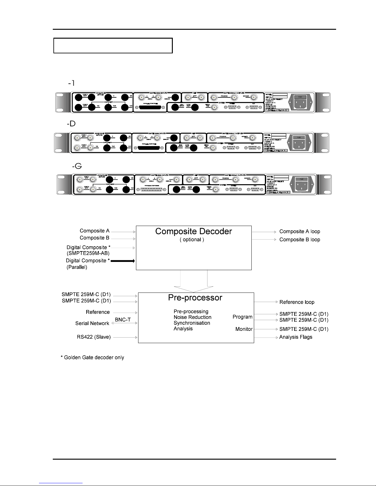
I/O & Interconnection
Subject to the options fitted, the following I/O rear panel connections will be available: -

CPP100 SECTION 1
CPP1OPS 25/10/06 www.snellwilcox.com Version 1 Issue 6 1.4
Composite inputs are decoded using an adaptive field-based comb-decoder and passed down the backplane
to the pre-processor card as separated luminance and multiplexed U/V. Up to two composite loop through
inputs can be applied simultaneously to the unit with switch selection between them on the decoder.
The optional ‘Golden gate’ decoder has the facilities to decode digital composite inputs in serial or parallel
format.
In addition to composite inputs, up to two serial digital component (SMPTE259M-C) inputs can be applied
directly to the pre-processor. Source switching between digital inputs is accomplished on the pre-processor
card.
An analogue loop-through reference may also be applied to the pre-processor card if the output is required to
be synchronised to a station reference. External communication is via a serial network (described more fully
later) connection to the pre-processor card. Internal communication is facilitated by a conventional CPU bus
link (address/data, ALE, WR, RD) between the three cards.
Filtered data sent from the pre-processor is formatted and the video output is then serialised into a
270Mbit/sec output as per SMPTE 259M-C.

CPP100 SECTION 1
CPP1OPS 25/10/06 www.snellwilcox.com Version 1 Issue 6 1.5
Pre Processor Overview
Recursive Filter
Recursive filters reduce noise by temporally
averaging successive pictures. Utilising delays of
exactly one picture or frame, noise can be reduced in
stationary areas without loss of spatial (horizontal and
vertical) resolution. Although temporal recursive
filters offer considerable levels of noise reduction,
sophisticated control logic is required to ensure that
picture detail is preserved at higher noise settings.
In particular, analysis of the noise floor level is
necessary to set movement thresholds at levels that
are just above the noise floor. At optimum settings
this allows maximum noise reduction and
simultaneously maximum sensitivity to movement.
Auto Threshold Bias
In auto threshold mode the noise detection algorithm
may be given a subjective bias to give more or less
noise reduction. Modification of the bias should not
be necessary under normal circumstances.
Y And C Recursive levels
These settings change the amount of noise reduction
for luminance (Y) and chrominance (C) by limiting the
maximum level of noise reduction. The actual level
of noise setting is dynamically adjusted on a pixel-bypixel basis with regard to the noise setting for the
same pixel in the previous frame. Other factors such
as movement contribute to the current pixel setting.
This mechanism ensures that the optimum level of
noise reduction is applied to each pixel.
Threshold
This sets the threshold for the motion detector. The
lowest level of 0 gives the greatest sensitivity to
motion, but allows more noise to break through, while
15 gives the greatest noise reduction but can lead to
excessive filtering of low-level textures. When this is
set to auto the threshold is dynamically set to an
appropriate value for the current input noise level.
Semi Transversal
The semi-transversal filter is a uniquely patented
design that operates in conjunction with the recursive
filter to increase its effectiveness. Quite unlike
traditional transversal filters it operates by selecting
the most appropriate outputs from a chain of picture
stores at the output of the recursive filter.
An algorithm is used to determine which of the stores
contains the highest level of noise-reduced picture.
The overall effect is to increase the amount of noise
reduction in a typical picture. For example, moving
objects cause the recursive filter to turn off at the
edge of the moving object. This leads to a
recurrence of noise that takes a number of frames to
reduce to the defined user level. The semitransversal filter is able to monitor the recurrence of
noise and delay the output of the recursive filter up to
a maximum of three frames. Operating on a pixel-bypixel basis, the overall level of noise reduction in a
typical picture is maintained at a more uniform level
and is less dependent on movement.
As the semi-transversal filter complements the
recursive filter, it cannot be utilised without the
recursive filter. Effective at all recursive filter settings
its operation can be seen as a reduction in the level
of revealed noise trail following moving objects.
The semi-transversal filter operates in a fully
automatic mode - there are no user adjustments
required.
Median Filter
Median filters can be effective at removing impulse
noise. They operate by rank filtering pixels from an
odd number of aperture points yielding the median
value. The aperture set may utilise the surrounding
pixels from the same field or more usually some
combination of pixels from current and adjacent fields
or frames.
When a pixel is judged to be in error it is replaced by
the median value of the aperture set. Pixels judged
not to be in error remain unaltered. The algorithm is
therefore quite specific about the areas of the picture
which are filtered.
An algorithm utilises both spatial and temporal
gradient information to determine if the suspect pixel
has impulse noise characteristics.

CPP100 SECTION 1
CPP1OPS 25/10/06 www.snellwilcox.com Version 1 Issue 6 1.6
Median level
Six settings are provided for the median filter level
control. The low setting provides modest filtering and
has high rejection of false alarms caused by picture
movement and texture etc. The medium and high
settings are biased increasingly towards removal of
larger dropouts and dirt but consequently may have a
higher false alarm rate resulting in a general
softening of the picture.
Spatial Filter
Spatial filtering typically involves filtering using an
aperture that comprises adjacent pixels from the
same field period. Spatial median filters can be
effective at suppressing impulse noise originating
from film dust or small dropouts. However they are
also effective as Gaussian noise reduction filters.
Y and C Spatial Levels
The spatial filter operates by median filtering a small
kernel of adjacent pixels and then comparing the
median filtered pixel level with the current pixel. The
spatial filter has three level settings that are used to
vary the comparison threshold and effectively set the
balance between the level of noise suppression and
detail preservation. Typically used in conjunction with
other temporal based filters such as the recursive
and transversal filters, spatial noise reduction can
increase the overall noise reduction level.
Linear Filters
A suite of linear filters allows fine control of the
horizontal bandwidth of the luminance signal.
Brickwall low-pass filters ranging from 2.5MHz to
4.2MHz provide good band-limiting facilities for
MPEG encoders that use half resolution processing.
These filters also provide variable peaking or
boosting at each of the selected cut-off frequencies.
Boosting prior to brickwall filtering can raise the
overall perception of picture sharpness. In addition to
the above filters there is a set of extra low pass filters
where greater band limiting is required. These filters
have a cut-off ranging from 2.4MHz to 0.9MHz.
The ten sets of Gaussian low-pass filters gently
attenuate high frequencies and can be used to
correct material which has previously been boosted
or enhanced as well as reducing high frequency
noise.
Similarly, five sets of Gaussian high-pass filters
provide variable correction of high-frequency
luminance that may have been attenuated from faulty
distribution links or analogue VTR processes.
Scratch Filter
This filter has been designed to detect and repair
vertical scratches, of variable contrast, and length, be
they black, white or both, while maintaining picture
quality where there are no scratches. To maximise
the benefit obtained from this filter, a suite of filter
strengths has been provided.

CPP100 SECTION 1
CPP1OPS 25/10/06 www.snellwilcox.com Version 1 Issue 6 1.7
Enhancer
The enhancer menu contains four different types of
filters: Enhance, MPEG De-enhance, Decoder
matching and Video mode. These filters are
exclusive and cannot be applied at the same time.
For example, it would be inappropriate to
simultaneously enhance and de-enhance the picture
and this option is excluded. Similarly, video modes
(which utilise the same adjacent fields and lines as
the de-enhancement filters) cannot be selected at the
same time as any of the other three filters.
The enhancer uses a combination of linear and nonlinear processes to generate edge correction and
peaking correction signals. The use of non-linear
processing ensures that high levels of correction are
possible without introducing edge distortion such as
overshoots and ringing normally associated with
traditional frequency boosting techniques.
Three settings of enhancement are provided for both
luminance and chrominance. Coring controls can be
used for noisy inputs to prevent enhancement of low
level noise. Three settings are provided for both
luminance and chrominance coring.
De-enhancement filtering can be used to suppress
high vertical\temporal frequencies that the MPEG
encoder may not be able to efficiently encode.
Material that originated on video with 60Hz or 50Hz
temporal sampling will encode less efficiently than
24Hz film originated material. For fixed or
multiplexed bit rate systems suppression of high
diagonal frequencies can reduce the peak bit rate
requirements.
A three dimensional vertical temporal filter is used to
provide suppression of moving and static diagonal
frequencies.
Three filter settings are provided for both luminance
and chrominance. They can be used to adjust the
degree of filtering from partial suppression of
diagonal frequencies at the low setting to full
suppression of diagonal frequencies over a wide
horizontal band at the high setting. Purely horizontal
frequencies remain unfiltered.
Three decoder matching settings are provided: Line
Comb, Field Comb and Other.. The purpose of each
of these filters is to provide complementary filtering
from a composite source which has been decoded
using a comb decoder such as NTSC/PAL line or
field comb.
A composite comb decoder will use a spatial or a
vertical/temporal aperture to separate luminance from
chrominance. With knowledge of the comb structure
the decoder matching filters in Prefix filter areas of
the spectrum which the composite decoder has not
previously filtered.
Cross-effects such as cross-colour (high frequency
luminance in chrominance) and cross luminance
(residual chrominance in luminance) are reduced in
amplitude.
The Line Comb setting is used for decoders which
utilise a line comb structure (vertical filter using
adjacent lines) for Y/C separation. The Field Comb
setting is used for decoder which utilise a field comb
structure based on 312H (PAL) or 263H (NTSC)
diagonal vertical/temporal filters such as the Prefix
internal field comb decoder.
For simple or notch decoders which do not utilise a
comb decoder strategy for Y/C separation or where
the Y/C separation strategy is unknown, the Other
setting provides good suppression of high frequency
diagonal components which may have originated
from cross-effects.
For video based inputs two modes of video filtering
can be used to reduce the temporal bandwidth of the
video source to 30/25Hz from an original 60/50Hz.
These operate by filtering and subsampling the video
inputs so that the output rate has been temporally
reduced.
An MPEG encoder operating in video mode will be
able to encode the filtered output more efficiently by
utilising the high level of correlation between adjacent
fields.
The two video modes are filtered differently prior to
temporal subsampling. Mode 1 provides a sharper
picture with a stronger 25Hz inter-frame component
than Mode 2 which has no inter-frame component but
has less overall vertical/temporal bandwidth. The
choice will be dependent on the available MPEG bit
rate and subjective picture tests.

CPP100 SECTION 2
CPP1OPS 25/10/06 www.snellwilcox.com Version 1 Issue 6 2.1
Installation
PREFIX is supplied in a dedicated carton provided by
the manufacturer and should not be accepted if
delivered in inferior or unauthorised material.
Carefully unpack the unit and check for any shipping
damage or shortages. If you encounter any problems
please report them to the supplier immediately.
IMPORTANT NOTE: In case of complaint the carrier
should retain the packing material for inspection.
The unit is designed for mounting in a 1RU slot in a
19" racking system.
The chassis is equipped with a pair of mounting ears
attached to the side plates. Suitable screws should
be inserted through the holes in these flanges to
secure the chassis to the racking system. Ensure that
the rack is correctly configured to accept the 1U unit
with chassis runners positioned to support the unit.
Under no circumstances should the unit be hung from
its rack ears alone as this will result in irreparable
damage to the case.
Whilst mounting the unit please try to ensure that
there is adequate airflow to the rear of the unit.
If a PREFIX is to be mounted in a rack together with
convection cooled equipment, e.g. Analogue
distribution amplifiers ensure that it is not located
above or interspersed with these units. The
equipment should be operated in an environment
having a temperature between 0oC and +30oC and a
relative humidity of less than non-condensing.
S N E L L & W I L C O X
C P P 1 0 0
HOME
PRESET
BACK
FREEZE BYPASS
REC TRANS MEDIAN SPATIAL
LINEAR SCRATCH
ENHANCE
SETUP MEM
CONFIG
NET
PATTERNMON
INPUT
GLK
FILTERS
PICTURE
PREFIX
SELECT
Pulling the two catches forwards opens the front
panel. We have found that the easiest way of doing
this is with your thumbs! The internal hinge
mechanism has been designed so that the panel can
hinge forwards and downwards to leave unrestricted
access to the boards.
Electrical Connection
The power supply accepts AC mains in the range 90
to 250 Volts AC @ 50Hz to 60Hz and will auto switch
to these standards. The main power connection,
located at the rear of the unit, is made via a fused
IEC320 inlet socket (fuse 2.5 AT, Max Current 1.8A)
with the middle pin as earth conductor. This electrical
connection should be located as close to the unit as
possible to facilitate easy isolation.
Power Switch
The power switch and the power-ON indicator are
located behind the front panel.

CPP100 SECTION 2
CPP1OPS 25/10/06 www.snellwilcox.com Version 1 Issue 6 2.2
Signal Connections
All external signal connections are made via the rear
panel.
Composite Analogue Inputs
The rear panel supports these inputs which are
labelled as COMP A and COMP B with loop through
indication. Nominal input level for analogue video is
1V peak to peak and a 75-Ohm termination must be
fitted if the loop through facility is not used.
Digital Inputs
The BNC connectors labelled 259M-C A and B
accept digital component signals. These inputs can
be selected from the menu by choosing the SDI-A or
SDI-B option.
Not that this interface is in accordance with SMPTE
259M-C ITU recommendation BT.656-3
‘Golden Gate’ Option
The ‘Golden gate’ option has two digital inputs. One
input is for serial digital video (in accordance with
SMPTE 259M-AB). The other input is for parallel
composite digital video via DB25 connector
(terminated in 110 Ohms ± 10 Ohms). 10m
maximum cable length using shielded multi-core
cable.
Reference Input
The reference accepts analogue video with a nominal
input level of 1V peak to peak. A 75-Ohm termination
must be fitted if the loop through facility is not used.
CPP100 SECTION 2
CPP1OPS 25/10/06 www.snellwilcox.com Version 1 Issue 6 2.3
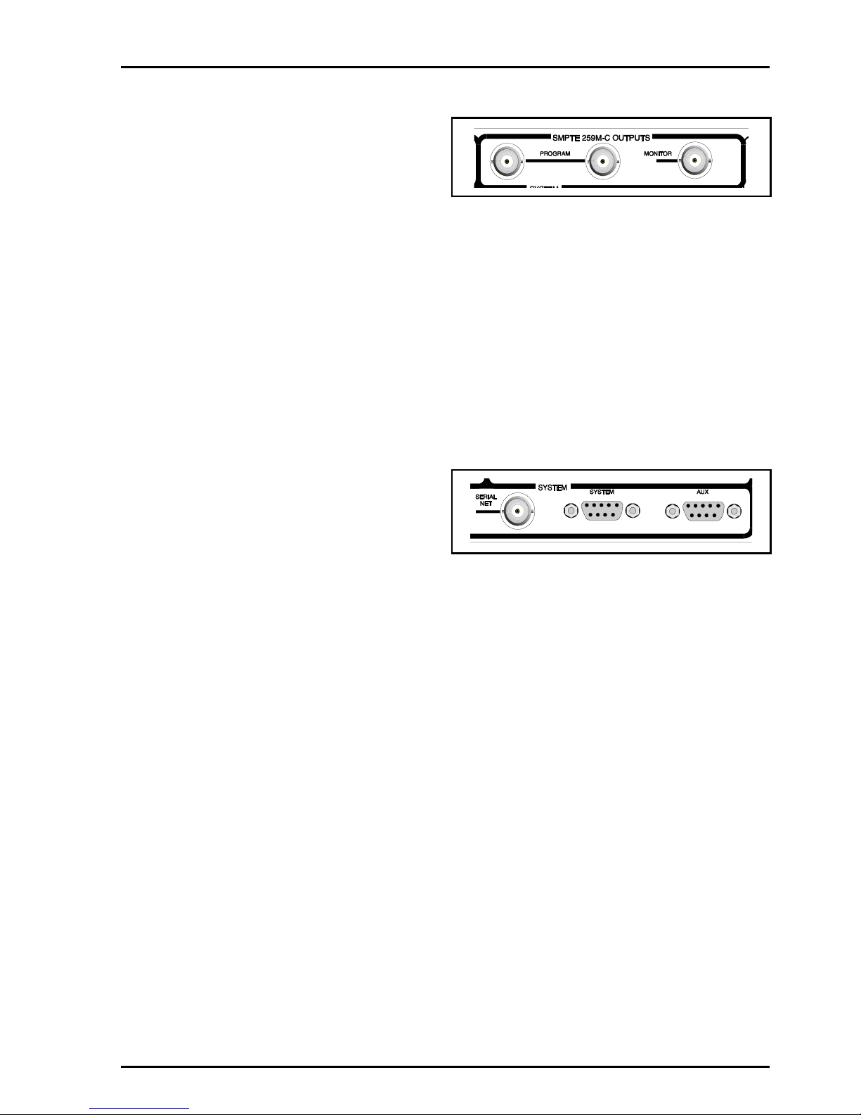
Digital Outputs
These are the SDI outputs from the unit via BNC
connectors. They are component digital outputs, all of
which can be used simultaneously.
The interface is in accordance with SMPTE 259M-C
ITU recommendation BT.656-3
The Program output carries processed video.
The monitor output carries processed video, and if
selected, the on-screen display.
Note that Error Detection and Handling (EDH) is only
implemented on the program output.
Note
To aid compliance with EMC/RFI regulations, we
recommend the use of high quality co-axial cable
type BBCPSF1/2 or equivalent.
Remote Control
Interface to the "RollCall" communications network is
via the single BNC connector labelled Serial Net.
Connections should be made by means of a `T' piece
(Zo=75 Ohms) to a 75 Ohm cable system with both
extremities terminated in 75 Ohms.
Under no circumstances should the "RollCall"
network be directly connected to any other
communications network such as a computer
"Ethernet" system.

CPP100 SECTION 3
CPP1OPS 25/10/06 www.snellwilcox.com Version 1 Issue 6 3.1
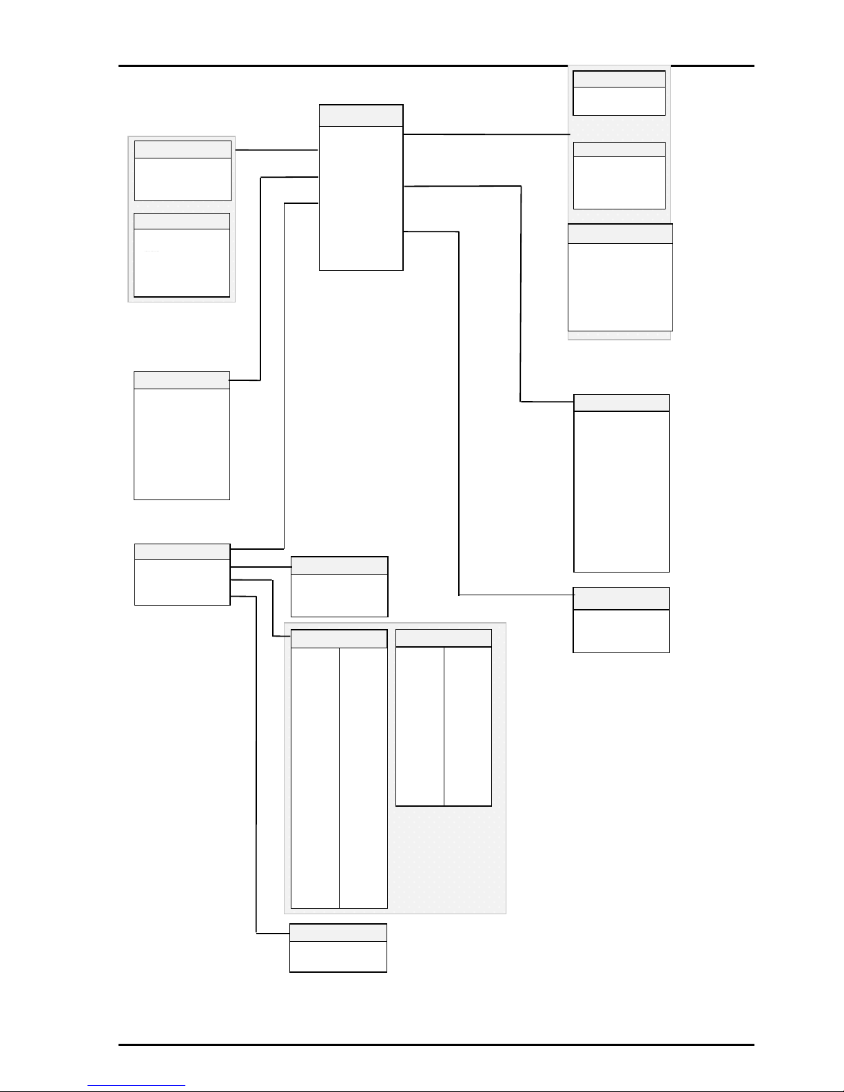
Block Diagram

CPP100 SECTION 4
CPP1OPS 25/10/06 www.snellwilcox.com Version 1 Issue 6 4.1
Getting Started
Connect up the unit so that there is a Analogue
Composite video signal applied to the composite
input or a Serial Digital video signal applied to the
SMPTE259M-C serial input. For Composite inputs
REMEMBER to fit a termination if the video loop
through is not used. Either one of the 2 serial outputs
can be used. A reference signal may be connected if
required.
The front panel is opened by using the two black
catches at either end of the panel. We have found the
best way of opening the panel is to use your thumbs
to release the catches and then ease the panel
sufficiently forward.
Turn the unit on. The green LED to the left of the
ON/OFF switch should be illuminated, and the fan
should be audible.
CPP100-D Version Only
The front panel display will indicate that the unit is
powering up and that the Xilinx and CPU devices are
being configured.
The display on the decoder card will indicate that the
Xilinx devices are being configured. The bar at the
end of the message will rotate during this process.
A scrolling message will then display the unit’s name
and the configuration status.
The initialisation sequence is now complete and the
output should be the decoded input.
SNELL & WILCOX
CPP-100
Booting Xilinx..
SNELL & WILCOX
CPP-100
Booting....
LED

CPP100 SECTION 4
CPP1OPS 25/10/06 www.snellwilcox.com Version 1 Issue 6 4.2
Card Edge Functions
Decoder Card -D
The upper card is the decoder. The LED will
illuminate if there is a loss of syncs on the analogue
input
Noise Reducer
The right hand pair of LEDs indicates the condition of
CPU A. The GREEN LED flashes when the CPU is in
normal operation. The RED LED illuminates on
power-up and if an internal error occurs.
Similarly the left-hand pair of LEDs indicate the
condition of CPU B.
If for any reason the menu system should hang the
CPU can be restarted with the CPU RESET switch.

CPP100 SECTION 4
CPP1OPS 25/10/06 www.snellwilcox.com Version 1 Issue 6 4.3
Decoder Card – ‘Golden Gate’ Option (-G)
Adjustment of the settings for the CPP100-G is
available via the RollCall remote control system.
LED INDICATORS
D1 (SOIRX)
This indicator will flash when RS422 data is being
received from the remote control port.
D2 (SIOTX)
This indicator will flash when RS422 data is being
transmitted to the remote control port.
D3 (DAT2)
This indicator will flash when network data is being
received from the RollCall remote control port.
D4 (DAT1)
This indicator will flash when network data is being
transmitted to the RollCall remote control port.
D5, D6, D7 & D8
These indicate that the -6 V, +5 V, +6 V and -5 V
power supplies are present.
D9 (INPUT)
This indicates the presence of a decoder
composite input.
D10 (REF)
This indicator is non-operational
D11 (DECODER ERROR)
This indicates a decoder error
D12 (EDH)
This indicator will flash when EDH errors are
detected
D13 (SCL) and D14 (SDA)
These are internal status indicators
D15 (ILF)
This indicator will flash if an internal load fault is
detected; continuous illumination indicates a faulty
unit.
SW7 and SW8
These two switches enable the RollCall network
address to be set. SW7 sets the MSB (most
significant bit) and SW8 sets the LSB (least
significant bit)
SW7 is factory set to 3 and SW8 to 1.
Do not change these settings
Note that switches SW1 and SW2 have no function
on the card.
CPP100 SECTION 5
CPP1OPS 25/10/06 www.snellwilcox.com Version 1 Issue 6 5.1
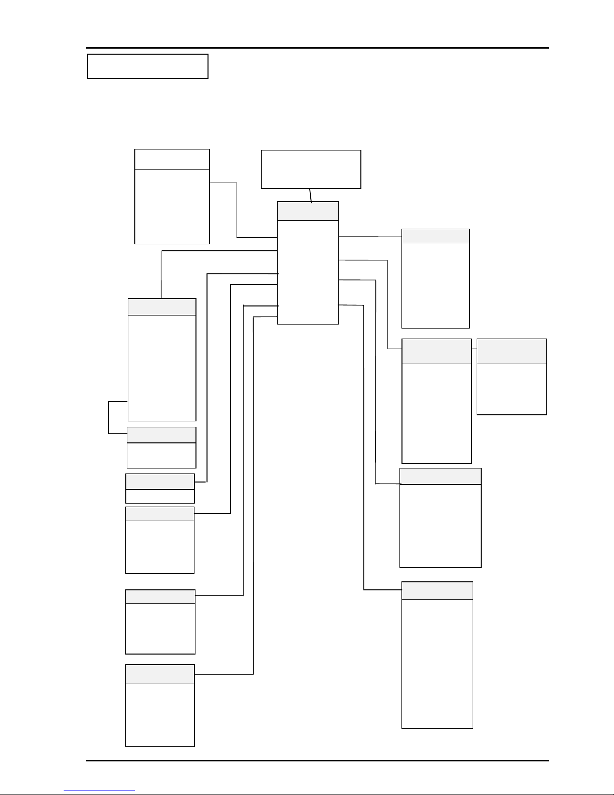
Menu System
Normal Panel Display and Top Level Menu Structure
Main Menu
▶
Filters
▶
Analysis
▶
Video
▶
Decoder
▶
RollTrack
▶
Genlock
▶
Monitor
▶
Memory
▶
Quick
Filters
▶
Recursive
▶
Median
▶
Spatial
▶
Linear
▶
Scratch
▶
Enhancer
Bypass
Video
▶
Source
▶
Standard
Pattern
▶
Pat Select
▶
On Fail
▶
VITS
8 Bit Round
▶
V-Std
▶
Monochrome
Genlock Menu
Genlock
▶
Status
▶
H-Lock
▶
V-Lock
Decoder-D
(Comp I/P)
▶
Pic Posn
▶
Dec Mode
▶
Proc Amp
▶
Blk Trk
▶
Col Filt
▶
Comb Mode
Vert Adap
Pedestal
Monitor
▶
Status Display
▶
Display Style
▶
Panel Display
▶
EDH Status
▶
EDH Reset
▶
Key Window
▶
Logging
Memory
▶
Recall Preset
▶
Recall User
▶
Store User
▶
Set Name
Quick
Recursive
Semi Trans
Median
Spatial
Linear
Scratch
Enhancer
Pattern
Freeze
Bypass
System
▶
Net Address
▶
Net Name
▶
Version
▶
G Version
▶
Serial No
SDI A: 625
Memory 1
REMOTE EDH
Analysis
▶
Flag Output
▶
Data Ident
TTL Flags
LED Flags
Seq Hold
Seq Offset
RollTrack Menu
V-Std
▶
VSTD 525
▶
ABD 625
Decoder-G
(Comp I/P)
▶
Pic Posn
▶
Proc Amp
▶
Comb Mode
▶
Pedestal

CPP100 SECTION 5
CPP1OPS 25/10/06 www.snellwilcox.com Version 1 Issue 6 5.2
Filter Menu
Filters
▶Recursive
▶Median
▶Spatial
▶Linear
▶Scratch
▶Enhancer
▶Bypass
Median
Median
▶Level
Median Level
▶Min1/Min2/
Med3/Med4
Max5/Max6
Preset
Linear
▶Mode
Linear:Mode
▶Off
▶Brickwall
▶Gaussian LP
▶
Gaussian HP
Mode:Brickwall
▶Mode
▶CutOff
▶Boost
Mode:Gaussian LP
▶Mode
▶Gain
Mode:Gaussian HP
▶Mode
▶
Gain
CutOff
▶4.2M to 2.5M LP
2.4M to 0.9M ELP
Preset
Gain
▶1dB to 6dB
Preset
Boost
▶None
1.0dB to 6.0dB
Preset
Gain
▶-4dB to -40dB
Preset
Spatial
Spatial
▶Luma
▶Chroma
Luma
▶ Off/Min
Med/Max
Preset
Chroma
▶ Off/Min
Med/Max
Preset
Recursive
Recursive
Semi Trans
▶Luma
▶Chroma
▶Threshold
▶Bias
Luma
▶ Off/Min
Med/Max
Preset
Threshold
▶Auto, 0-15
Preset
Bias
▶-3 to +3
Preset
Chroma
▶ /Off/Min
Med/Max/
X- Colour
Preset
Enhancer
▶Mode
Enhancer:Mode
▶Off
▶Enhance
▶MPEG De-Enhance
▶Decoder Match
▶Video Filter
Mode:Enhance
▶Mode
▶Luma
▶Chroma
▶Coring
Mode:MPEG De-Enhance
▶Mode
▶Luma
▶Chroma
Mode:Decoder Match
▶Mode
▶Decoder Type
Frame Mode
▶Mode1/Mode2
Preset
Chroma
▶Off/Min/Med/Max
Preset
Mode:Video Filter
▶Mode
▶Frame Mode
Decoder Type
▶Line Comb/
Field Comb/
Other
Preset
Luma
▶Off/Min/Med/Max
Preset
Luma
▶Off/Min/Med/Max
Preset
Chroma
▶Off/Min/Med/Max
Preset
Chroma
▶Off/Min/Med/Max
Preset
Coring
Luma
▶Off/Min/Med/Max
Preset
Scratch Strength
▶Min/Med/Max
Preset
Scratch
Scratch
▶Strength
▶Contrast
▶Type
▶ Length
▶ Width
Scratch Contrast
▶Low/Med/High
Preset
Scratch Type
▶Both/White/Black
Preset
Scratch Length
▶Any/Long
Preset
▶Luma
▶Chroma
Scratch Width
▶Wide/Narrow
Preset

CPP100 SECTION 5
CPP1OPS 25/10/06 www.snellwilcox.com Version 1 Issue 6 5.3
Analysis
Analysis
▶
Flag Output
▶
Data Ident
TTL Flags
LED Flags
Seq Hold
Seq Offset
▶
Flag 0
Flag 1
Flag 2
Flag 3
TTL Flags
▶
Off
▶
Shot Change
Adv Shot Change
▶
Repeat Field
▶
3:2 Seq, bit 2
▶
3:2 Seq, bit 1
▶
3:2 Seq, bit 0
▶
Seq Change
▶
Single Field
▶
Not Film
▶
First Field
▶ ~
Shot Change
~Adv Shot
Change
▶ ~
Repeat Field
▶ ~
3:2 Seq, bit 2
▶ ~
3:2 Seq, bit 1
▶
~3:2 Seq, bit 0
▶ ~
Seq Change
▶ ~
Single Field
▶ ~
Not Film
Flag 0,1,2,3
Data Ident
c0 (hex)
To
df (hex)
CPP100 SECTION 5
CPP1OPS 25/10/06 www.snellwilcox.com Version 1 Issue 6 5.4
Video Menu
Video
▶Source
▶Standard
Pattern
▶Pat Select
▶On Fail
▶VITS
8 Bit Round
▶V Std (525)
▶ ABD (625)
▶ Monochrome
SDI Input
▶625
▶525
▶Auto
Comp Input
▶PAL-I
▶PAL-M
▶NTSC
▶Auto
Source - 1
▶SDI A
▶
SDI B
Source - D
▶Comp A
▶Comp B
▶SDI A
▶
SDI B
Pattern Select
▶Black
▶EBU Bars
▶Y Ramp
▶UV Ramp
▶Y Sweep
▶UV Sweep
▶Bowtie
▶Full Bars
On Fail
▶SDI B
▶Freeze (SDI I/P)*
▶Video(Comp I/P)*
▶Message
▶Black
▶EBU Bars
▶Y Ramp
▶UV Ramp
▶Y Sweep
▶UV Sweep
▶Bowtie
▶Full Bars*
V Std (525 only )
▶OVD
▶OBD
▶ABD
VITS
▶All
▶Select*
▶Mode*
All
▶All On
▶All Off
▶User Cfg
Mode (Comp I/P)
▶Decoded
▶Composite
Select (625)
318*
319
320
321
322
323
324
325
326
327
328
329
330
331
332
333
334
335
6
7
8
9
10
11
12
13
14
15
16
17
18
19
20
21
22
Select (525)
272
273
274
275
276
277
278
279
280
281
282
10
11
12
13
14
15
16
17
18
19
20
Product Input
Option Type
-1 SDI Only
-D SDI and Composite
-G SDI and Parallel
Source - G
▶Dig Comp
▶Ana A
▶Ana B
▶Parallel
▶SDI A
▶SDI B
*
Not available
on –G version

CPP100 SECTION 5
CPP1OPS 25/10/06 www.snellwilcox.com Version 1 Issue 6 5.5
Decoder Menu
Note: The decoder sub-menu is only available if the optional decoder card is fitted and composite video input is
selected. The Comb Mode menu is only available with the ‘Golden Gate’ option.
Genlock Menu
Decoder
( Comp I/P )
▶Pic Posn
▶Dec Mode*
▶Proc Amp
▶Blk Trk*
▶Col Filt*
▶Comb Mode
Vert Adap*
Pedestal
(NTSC only on
-G version)
Pic Posn
▶0 ns
Preset
Dec Mode
▶Decode
▶Comp
Proc Amp
▶Black*
▶Vid Gain
▶C Gain
▶Hue
Black
▶0 mV
Preset
Vid Gain
▶0 dB (100% -G)
Preset
C Gain
▶0 dB (100% -G)
Preset
Blk Trk
▶Off
▶On
▶Align
Col Filt
▶Wide
▶Medium
▶Narrow
Comb Mode
▶Studio 1
▶L Disk
▶VHS
▶Studio 2
▶Line
▶Still
▶Simple 1
▶Simple 2
Genlock
Genlock
▶Status
▶H-Lock
▶V-Lock
H-Lock
▶0 ns
Preset
V-Lock
▶0 lines
Preset
<Status>
I/P Lock
Hue ( NTSC )
▶0 Hue (0° -G)
Preset
*
Not available on –G version
Note that on –G versions
units for Gain are % and
for Hue °

CPP100 SECTION 5
CPP1OPS 25/10/06 www.snellwilcox.com Version 1 Issue 6 5.6
Monitor Menu
Monitor
▶Status Display
▶Display Style
▶Panel Display
▶EDH Status
▶EDH Reset
▶Key Window
▶Logging
Status Display
▶None
▶System
▶Filters
▶Decoder (Comp I/P)
<EDH Status>
OK
Panel Display
▶Normal
▶Recursive
▶Median
▶Spatial
▶Linear
▶Scratch
▶Enhancer
▶EDH Check
▶Network
▶Auto Loop
Display Style
▶Black/White
▶White/Black
▶White/Clear
EDH Reset
▶AP Reset
▶FF Reset
▶Reset Both
Border
▶Off
▶Black
▶White
Key Window
▶Window Select
▶Border
▶Set User
Invert
Window Select
▶Off
▶H-Split
▶V-Split
▶Box
▶User
▶H Repeat
Set User
▶X1
▶Y1
▶X2
▶Y2
X1
▶0 pixels
Preset
Y1
▶0 lines
Preset
X2
▶0 pixels
Preset
Y2
▶0 lines
Preset
Logging
▶Log Input State
▶Log Ref State
▶Log EDH State
▶Log ERR Secs
▶Log Server Name

CPP100 SECTION 5
CPP1OPS 25/10/06 www.snellwilcox.com Version 1 Issue 6 5.7
Memory Menu
Quick Menu
Quick
Recursive
Semi Trans
Median
Spatial
Linear
Scratch
Enhancer
Pattern
Freeze
Bypass
Memory
▶Recall Preset
▶Recall User
▶Store User
▶Set Name
<Set Name>
[As Factory ]
Preset
▶Satelite Noise
▶Film Artefacts
▶Video Artefacts
▶F & V Artefacts
▶MPEG Lo bps Fil
▶MPEG Med bps Fi
▶MPEG Hi bps Fil
▶MPEG Lo bps Vid
▶MPEG Med bps Vi
▶MPEG Hi bps Vid
▶Factory
Recall Preset
▶Empty 1
▶Empty 2
▶Empty 3
▶Empty 4
▶Empty 5
▶Empty 6
▶Empty 7
▶Empty 8
Recall User
Store User
▶Empty 1
▶Empty 2
▶Empty 3
▶Empty 4
▶Empty 5
▶Empty 6
▶Empty 7
▶Empty 8

CPP100 SECTION 5
CPP1OPS 25/10/06 www.snellwilcox.com Version 1 Issue 6 5.8
System Menu
Character set for < Net Name > and < Memory Name >
System
▶Net Address
▶Net Name
▶Version
▶G Version
▶ Serial No
Net Address
▶20 h
Preset
<Net Name>
[CPP100(20) ]
Preset
<Version >
a.bb c
<G Version >
a.bb c
<Serial No >
xxxxxxx

CPP100 SECTION 6
CPP1OPS 25/10/06 www.snellwilcox.com Version 1 Issue 6 6.1
Operation
GENERAL
SNELL & WILCOX
CPP 100
HOME
PRESET
BACK
FREEZE
BYPASS
REC TRANS MEDIAN SPATIAL
LINEAR SCRATCH
ENHANCE
SETUP MEM
CONFIG
NET
PATTERN
MON
INPUT
GLK
FILTERS
PICTURE
PREFIX
SELECT
All operational parameters and selections are made using a system of menus as shown in the previous
section. A guide to controlling the PREFIX and what the operational parameters and selections do can be
found in this section.
The PREFIX may be controlled by a number of different means:-
- Local front control panel,
- Remote “Shoe Box”
- Computer Interface
- Card Edge Control (not available on –G version)
When using a Remote “Shoe Box” or the computer interface, communication is via a wired network system
called RollCall. Several units may be controlled using this system. Further details can be found in section 7
and the “Shoe Box” operation manual.
If the PREFIX is fitted with a decoder card ( top slot ) the unit may be controlled by using the interface fitted to
this card. This interactive user interface consists of a high contrast 8 character display and a bank of four push
button switches, both of which are accessed by opening the front panel. Further details of this method of
control can be found at the end of this section.

CPP100 SECTION 6
CPP1OPS 25/10/06 www.snellwilcox.com Version 1 Issue 6 6.2
Front Panel Control
SNELL & WILCOX
CPP 100
HOME
PRESET
BACK
FREEZE
BYPASS
PICTURE
PREFIX
SELECT
Menus are selected by using the spinwheel and the SELECT button. The two arrows to the right of the panel
display indicate that more items are available, to view these use the spinwheel to scroll the display. The bottom
line of the front panel is used to display unit status and warning messages.
The spinwheel can also be used to adjust parameters such as the Horizontal Genlock Offset.
SELECT Use this button to select a menu item, select a parameter or turn a feature on.
PRESET Use this button to choose the factory preset for the chosen parameter
HOME Return the menu to the NORMAL panel display
PREV Go Back up the menu structure one level
Panel Lock
A facility exists where the front panel can be locked out. This may be useful where accidental depression of
one of the control buttons could occur or where the unit will be under remote control. To enter this mode press
SELECT + HOME together. A status message, “PANEL LOCKED” , will be displayed on the front panel. To
unlock the front panel press SELECT + HOME together again.
Picture
Button Press
FREEZE On / Off
BYPASS On / Off
FREEZE
This performs a full frame picture freeze at the input to the PREFIX. The freeze button has a status LED, when
this is illuminated Freeze is ON, when the LED is extinguised Freeze is OFF. A status message, “FREEZE” ,
will be displayed on the front panel.
BYPASS
This button is used to turn the signal processing ON and OFF. When Bypass is turned ON all the filters are
effectively turned OFF. This allows for a whole picture comparison of pre-processed against unprocecessed
without using the key window facility. When Bypass is on the green status LED in the button flashes. A status
message , “BYPASS” , will be displayed on the front panel.
Panel Display
SPINWHEEL

CPP100 SECTION 6
CPP1OPS 25/10/06 www.snellwilcox.com Version 1 Issue 6 6.3
Filters
REC TRANS MEDIAN SPATIAL
LINEAR SCRAT CH
ENHANCE
SETUP MEM
CONFIG
NET
PATTERN
MON
INPUT
GLK
FILTERS
The set of seven ‘FILTERS’ buttons on the front panel can be used to access and control the filters.
Button Press Press and Hold
REC On / Off Goto Recursive filter menu
TRANS On / Off Goto Recursive filter menu
MEDIAN On / Off Goto Median filter menu
SPATIAL On / Off Goto Spatial filter menu
LINEAR On / Off Goto Linear filter menu
SCRATCH On / Off Goto Scratch filter menu
ENHANCE On / Off Goto Enhancer filter menu
Each of the filter push buttons has a green LED indicator. When the LED is illuminated the Filter is ON, when
the LED is extinguished the Filter is OFF.
CONFIG
The set of seven ‘CONFIG’ buttons on the front panel can be used to access and control the set up and
configuration of the unit.
Button Press Press and Hold
INPUT Goto Video-Source menu No Action
SETUP Goto Video menu Goto Decoder menu ( Comp I/P )
MEM Goto Memory-Recall User menu Goto Memory-Recall Presets menu
NET Goto System menu Goto System-Net Name menu
GLK Genlock ON/OFF Goto Genlock menu
MON On Screen Status Display ON/OFF Goto Monitor-Status Display menu
PATTERN Pattern ON/OFF Goto Video-Pat Select menu
The GLK, MON and PATTERN buttons have a green LED indicator. When the LED is illuminated the feature is
ON, when the LED is extinguished the feature is OFF. If the GLK button is flashing it means that there is a
Genlock error. For further information see the paragraph on Genlock in the following section.
The INPUT and NET buttons have a red LED indicator. If these LEDs flash it means there is an input signal or
network error. For further information see the following section.

CPP100 SECTION 6
CPP1OPS 25/10/06 www.snellwilcox.com Version 1 Issue 6 6.4
Filter Menu
This section provides a brief overview of the filter
controls. For a more detailed and in depth
explanation please see Appendix 1.
Recursive
This is the top level Recursive Filter menu.
To go directly to this menu PRESS and HOLD the
REC button on the front panel.
The Recursive filter can be turned ON/OFF directly
from the front panel by pressing the REC button.
The Semi Transversal Filter can be turned
ON/OFF directly from the front panel by pressing
the TRANS button. Note : The Semi Transversal
filter can only be turned ON/OFF if the Recursive
filter is ON
Semi-Transversal
Default Off
Recursive Luma Level
Range Off/Min/Med/Max
Preset Min
Recursive Chroma Level
Range Off/Min/Med/Max/X-Color
Preset Min
Recursive Threshold
Range Auto, 0-15
Preset Auto
Recursive Bias
Range -3 ... 0 ... +3
Preset 0
Recursive
Recursive
Semi Trans
▶Luma
▶Chroma
▶Threshold
▶Bias
Filters
▶Recursive
▶Median
▶Spatial
▶Scratch
▶Linear
▶Enhancer

CPP100 SECTION 6
CPP1OPS 25/10/06 www.snellwilcox.com Version 1 Issue 6 6.5
Median
This is the top level Median Filter menu.
To go directly to this menu PRESS and HOLD the
MEDIAN button on the front panel.
The Median filter can be turned ON/OFF directly
from the front panel by pressing the MEDIAN
button.
Median Level
Range Min1/Min2/Med3
Med4/Max5/Max6
Preset Min1
Spatial
This is the top level Spatial Filter menu.
To go directly to this menu PRESS and HOLD the
SPATIAL button on the front panel.
The Spatial filter can be turned ON/OFF directly
from the front panel by pressing the SPATIAL
button.
Spatial Luma Level
Range Off/Min/Med/Max
Preset Min
Spatial Chroma Level
Range Off/Min/Med/Max
Preset Min
Scratch
This is the top level Scratch Filter menu.
To go directly to this menu PRESS and HOLD the
SCRATCH button on the front panel.
The Scratch filter can be turned ON/OFF directly
from the front panel by pressing the SCRATCH
button.
Scratch Strength
Range Min/Med/Max
Preset Min
Scratch Contrast
Range Low/Med/High
Preset High
Scratch Type
Range Both/W hite/Black
Preset Both
Scratch Length
Range Any/Long
Preset Long
Scratch Width
Range W ide/Narrow
Preset Wide
Median
Median
▶Level
Spatial
Spatial
▶Luma
▶Chroma
Scratch
Scratch
▶Strength
▶Contrast
▶Type
▶Length
▶Width

CPP100 SECTION 6
CPP1OPS 25/10/06 www.snellwilcox.com Version 1 Issue 6 6.6
Linear
This is the top level Linear Filter menu when the
filter is turned OFF.
If the Linear filter is turned on in one of the three
operating modes the top level Linear Filter menu
will show the different options available for that
operating mode.
To go directly to this menu PRESS and HOLD the
LINEAR button on the front panel.
The Linear filter can be turned ON/OFF directly
from the front panel by pressing the LINEAR
button.
Linear : Mode
The default operating mode is Brickwall
Linear : Brickwall CutOff
The Brickwall filter has two sets of low pass filters.
The first set of Low Pass (LP) has a variable boost
available. The second set of Extra Low Pass (ELP)
filters has a fixed level of boost.
Low Pass (LP)
Range 4.2 MHz to 2.5 MHz
Step 0.1 MHz
Boost Variable, 1dB to 6dB
Extra Low Pass (ELP)
Range 2.4 MHz to 0.9 MHz
Step 0.3 MHz
Boost Fixed
Preset Low Pass 4.2 Mhz
Linear : Brickwall Boost
Range 1dB , 2dB , 3dB , 4.5dB , 6dB
Preset None
Variable Boost is only available with the
Low Pass Brickwall filters.
Linear : Gaussian LP Gain
Range -4dB to -40dB
Step -4dB
Preset -4dB
Linear : Gaussian HP Gain
Range 1dB , 2dB , 3dB , 4.5dB , 6dB
Preset 1dB
Linear:Mode
▶Off
▶Brickwall
▶Gaussian LP
▶Gaussian HP
Linear
▶Mode
Mode:Brickwall
▶Mode
▶CutOff
▶Boost
Mode:Gaussian LP
▶Mode
▶Gain
Mode:Gaussian HP
▶Mode
▶Gain

CPP100 SECTION 6
CPP1OPS 25/10/06 www.snellwilcox.com Version 1 Issue 6 6.7
Enhancer
This is the top level Enhancer Filter menu when the
filter is turned OFF.
If the Enhancer is turned on in one of the four
different operating modes the top level Enhancer
menu will show the different options available for
that operating mode.
To go directly to this menu PRESS and HOLD the
ENHANCE button on the front panel.
▶
The Enhancer filter can be turned ON/OFF directly
from the front panel by pressing the ENHANCE
button.
Enhancer : Mode
This selects the Enhancer operating mode. The
default mode is Enhance.
Enhancer : Enhance
Luma Level
Range Off/Min/Med/Max
Preset Min
Chroma Level
Range Off/Min/Med/Max
Preset Min
Luma Coring
Range Off/Min/Med/Max
Preset Off
Chroma Coring
Range Off/Min/Med/Max
Preset Off
Enhancer : MPEG De-Enhance
Luma Level
Range Off/Min/Med/Max
Preset Min
Chroma Level
Range Off/Min/Med/Max
Preset Min
Enhancer : Decoder Match
Decoder Type
Range Line Comb / Field Comb / Other
Preset Other
Enhancer : Video Filter
Frame Mode
Range Mode1 / Mode 2
Preset Mode 1
Enhancer:Mode
►Off
►Enhance
►MPEG De-Enhance
►Decoder Match
►Video Filter
Enhancer
▶Mode
Mode:Enhance
▶Mode
▶Luma
▶Chroma
▶Coring
Mode:MPEG De-Enhance
▶Mode
▶Luma
▶Chroma
Mode:Decoder Match
▶Mode
▶Decoder Type
Mode:Video Filter
▶Mode
▶Frame Mode

CPP100 SECTION 6
CPP1OPS 25/10/06 www.snellwilcox.com Version 1 Issue 6 6.8
Video Analysis Flags
Background
The ‘Prefix’ Compression Pre-Processor range has been designed with the following primary goals:
• To provide ‘clean’ decoding and high quality interfacing to a wide variety of input sources such as PAL or
NTSC composite and 625/525 component signals.
• To remove or reduce picture impairments caused by electronic processing or satellite transmission
failures.
• To limit the bandwidth of the picture to a level commensurate with the MPEG encoder bit rate.
• To generate video analysis information which a downstream MPEG encoder can use.
Video Analysis Information
Prefix has been designed to provide the following analysis information:
• Shot change detection
• Advanced Shot Change detection
• Film 3:2 sequence detection for 525 film originated material
• Explicit 3:2 sequence data for 525 film originated material
• Sequence change detection
• Single Field Flag
• Film/Video Identification
• Film frame pairing for 625 originated film
• Input Noise floor level
• Filter Status

CPP100 SECTION 6
CPP1OPS 25/10/06 www.snellwilcox.com Version 1 Issue 6 6.9
Shot Change detection
The presence of a shot change is detected by the analysis of picture difference between frames and fields.
Film material, which is frame based, will generate a strong intra frame correlation i.e. there will be no motion
differences between fields, which originate from the same film frame.
On the other hand, video originated material, which has individual fields representing different points in time
has no frame correlation. Nevertheless, at the presence of a shot change the integrated field and frame
difference outputs will show a distinctive pattern, which can be correlated, to identify the exact field where the
shot change occurs.
The shot change flag is a single line active high immediately after the shot change and is cleared at the end of
the following field.

CPP100 SECTION 6
CPP1OPS 25/10/06 www.snellwilcox.com Version 1 Issue 6 6.10
Advanced Shot Change
The shot change flag can be advanced by up to 5 fields in 1 field increments to allow downstream equipment
to prepare for the occurrence of a shot change.

CPP100 SECTION 6
CPP1OPS 25/10/06 www.snellwilcox.com Version 1 Issue 6 6.11
Repeat Field Flag for 525 film originated material
Film material, which is scanned by telecine to produce a 525 line output, uses the well known 3:2 pulldown
technique to insert an additional field for each pair of film frames. This has the effect of increasing the output
field rate to 60Hz required for 525 distribution.
The output video signal has a distinctive pattern of 2 fields followed by 3 fields followed by 2 field’s etc... The
five field sequence can be identified by indicating the position of the repeat field as shown below.
Sequence count for 525 film originated material
The five field sequence can be further identified by a specific code for each field in the sequence. In the
example shown below a 3-bit code running from 0 to 4 is used to explicitly identify each field in the 3:2
sequence.
Post produced electronic editing
Although the process of detecting the 3:2 sequence is relatively straight forward, complications arise whenever
material is electronically edited. This causes temporary discontinuities in the 3:2 sequence at the edit point.
Downstream equipment which relies on the accuracy of this flag could be affected if the sequence counter
does not correspond exactly to the video at the edit point. Prefix uses a correlation algorithm to:
• detect the edit
• analyse the 3:2 sequence following the edit
• provide accurate co-timed sequence count at Prefix output

CPP100 SECTION 6
CPP1OPS 25/10/06 www.snellwilcox.com Version 1 Issue 6 6.12
Sequence change
An example of an electronic edit to a film-originated master is shown below.
In this case, the edit has caused a discontinuity in the sequence count resulting in the counter value changing
from a 2 back to a 1 at the edit point. Prefix will accurately detect the edit and adjust the sequence count value
until it is co-timed with the video output.
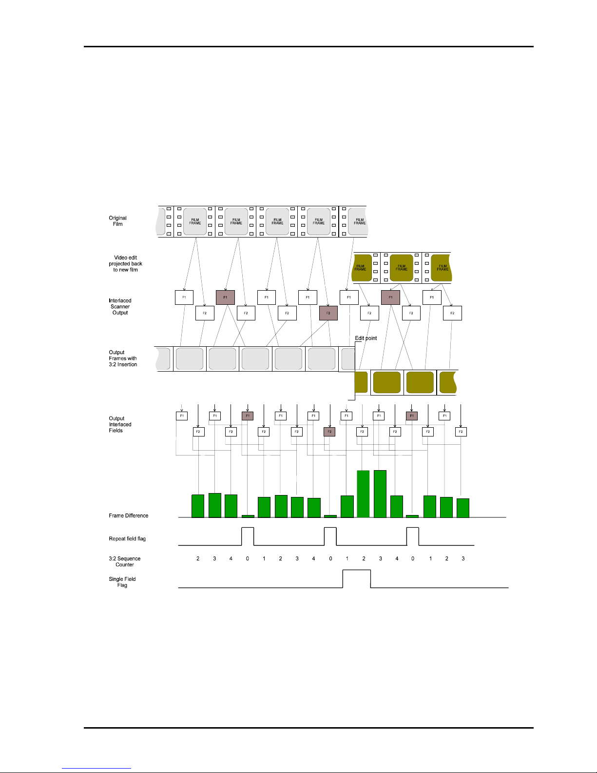
CPP100 SECTION 6
CPP1OPS 25/10/06 www.snellwilcox.com Version 1 Issue 6 6.13
Single Field Flag
In the following example, an electronic edit has occurred but in this instance there is no disturbance to the 3:2
sequence count. Nevertheless, downstream equipment, which performs some form of interpolation, would
generate a mixed output if fields corresponding to sequence counts 1 and 2 were treated as though there were
from the same film frame. To prevent this, a single field flag is generated which indicates to downstream
equipment that this field should be treated as a single field. In the instance shown, the single field flag is active
for two consecutive fields to indicate that an edit has occurred such that two single fields have been generated
from two original film frames containing different picture material.

CPP100 SECTION 6
CPP1OPS 25/10/06 www.snellwilcox.com Version 1 Issue 6 6.14
First Field Flag
The first field flag indicates the first field of a film frame as shown in the example below for 525 film originated
material. In this case, the first field flag will always correspond to a sequence count value of 1 or 3.

CPP100 SECTION 6
CPP1OPS 25/10/06 www.snellwilcox.com Version 1 Issue 6 6.15
Film / Video Identification
Film is scanned directly to produce a 625 line 50Hz output by running the telecine at 25/24 normal speed. The
resulting output has pairs of fields corresponding to each original film frame. No additional fields are required,
as the resulting frame rate of 25Hz is exactly correct for the 625 line standard. The frame pairs are identified
by analysis of field differences.
Film originated material has a high level of picture correlation on fields which are extracted from the same film
frame. Processed picture differences will produce a characteristic frame rate output signal as shown below.
Correlation algorithms within ‘Prefix ‘ are used to extract the film sequence and identify the source as film
originated.

CPP100 SECTION 6
CPP1OPS 25/10/06 www.snellwilcox.com Version 1 Issue 6 6.16
A video-originated source however, has no such frame correlation. A single line is used to indicate film/video
origination and is provided at the start of each field. If the material contains mixed film and video originated
material then the flag changes state immediately prior to the start of the first field of the film/video edit.

CPP100 SECTION 6
CPP1OPS 25/10/06 www.snellwilcox.com Version 1 Issue 6 6.17
Noise floor measurements
A proprietary algorithm is used to measure input noise floor level. This is used internally to control operation of
the median, recursive and de-enhancement filters and can be passed out along with the other video analysis
information.
Filter Status
Filter status (active or inactive) is reported through this register.

CPP100 SECTION 6
CPP1OPS 25/10/06 www.snellwilcox.com Version 1 Issue 6 6.18
Embedded Video Flags (in the ancillary data space)
Introduction
Provision exists to embed ancillary data within the SMPTE259 serial digital output. The flag
information is embedded in the Horizontal Ancillary (HANC) data space on one line per field.
Ancillary Data Packets are divided into Type 1 and Type 2, where Type 1 uses a single
word for data identification and Type 2 uses two words for this purpose.
Prefix has been designed to embed ancillary data as type 1 utilising a single data ID for
identification of the ancillary data packet.
Packet Structure
The structure of the packet data follows the convention laid down by the reference
documents for ancillary data of type 1.
For simplicity of hardware, Prefix utilises a module, which is common to both EDH and
ancillary data generation. Both packets have identical structure although the ancillary data
packet is located immediately following the EAV group whereas the EDH packet occurs
immediately prior to the SAV group.
Only the top 8 MSB’s of the output data stream are used to ensure no losses through 8-bit
equipment.
The structure is shown below.

CPP100 SECTION 6
CPP1OPS 25/10/06 www.snellwilcox.com Version 1 Issue 6 6.19
HANC: Horizontal Ancillary Header
The HANC header is as specified in REC656 as a 3 byte header in the form 000 3FF 3FF.
DID: Data Ident
The DID consists of 10 bits, of which 8-bits carry the identification value and the remaining
bits carry even parity and its inverse as shown:
bits b7 (MSB) - b0 (LSB) form the identification value (00h - FFh)
bit b8 is even parity for b7 - b0
bit b9 = not b8
DID words
Some DID words such as EDH are “Internationally Registered” and are unavailable for
selection.
Words in the range C0h to DFh are available for user application and may be assigned
for use in Prefix as shown in the table below.
DID
10-bit
DID
8-bit
C0
✔
C1-C3
✘
C4
✔
C5-C7
✘
C8
✔
C9-CB
✘
CC
✔
CD-CF
✘
D0
✔
D1-D3
✘
D4
✔
D5-D7
✘
D8
✔
D9-DB
✘
DC
✔
DD-DF
✘
To retain 8-bit compatibility the range of allowed values is restricted to the entries
marked with a tick.

CPP100 SECTION 6
CPP1OPS 25/10/06 www.snellwilcox.com Version 1 Issue 6 6.20
DBLK: Data Block Number
The data block number is incremented by 1 for each consecutive data packet sharing a
common DID and requiring continuity indication. This is always set to zero in Prefix.
DCN\\\\SNELLWILCOX.LOCAL\\ROOT\\MARKETING\\PRODMGMT\\DATA
Data Count
This byte represents the number of user data words to follow, and in this case it is always
set to 16.
C/SUM: Check Sum
The checksum word is used to determine the validity of the Ancillary Data Packet from the
DID through the user defined words (UDWs). The checksum value is equal to the nine
least significant bits of the sum of the DID, the DBLK the DCNT and all UDWs in the packet.
In 8-bit applications, where the two LSBs of every 10-bit word in the packet are set to zeros,
the C/SUM word is calculated in the same way as for 10-bit applications. (The LSBs
produce a zero sum themselves and produce no carry bit).
User data words: (UDW)
All user defined words can be described as bitwise utilising bits 2 through 7 with bit 8
defined as parity and bit9 set to “NOT bit 8”.
To ensure that no data is lost through 8 bit equipment, bits 1 & 0 are not used
Positioning
The flag information is inserted on the following lines: -
HANC 625 line Standard 525 line Standard
Field 1 6 10
Field 2 319 273
NOTE - although it is recommended that Ancillary Data Packets are not transmitted within
the ancillary space on line 10/273 or line 6/319 (as switching may occur during these lines),
receiving equipment should process ancillary data located in any ancillary data space.
Synchronous switching of picture sources will invalidate the analysis information in any
case; therefore it is convenient to locate the data on the switching lines for the configuration
where Prefix analysis data is used with a compression encoder.
Additionally, these lines have been chosen because they are guaranteed to be free from
embedded audio packets, which are not permitted on the switching lines.

CPP100 SECTION 6
CPP1OPS 25/10/06 www.snellwilcox.com Version 1 Issue 6 6.21
Groups
The flag information is arranged into individual Groups as shown below
Word Number Group Word Count
1 Film I 1
2 Film II 1
3 Noise Floor 1
4-8 Status 5
Film Group I
Group Word Bit Flag
9~b8
8 parity
7 single field flag
Film I 1 6 sequence change
5 shot change
4 sequence count bit 2
3 sequence count bit 1
2 sequence count bit 0
Film Group II
Group Word Bit Flag
9~b8
8 parity
70
Film II 1 6 0
5 repeat field flag
4 ~ film
3 advance shot change
2 first field flag
Noise Floor Group
Group Word Bit Flag
9~b8
8 parity
7 Noise floor bit 5
Noise Floor 1 6 Noise floor bit 4
5 Noise floor bit 3
4 Noise floor bit 2
3 Noise floor bit 1
2 Noise floor bit 0

CPP100 SECTION 6
CPP1OPS 25/10/06 www.snellwilcox.com Version 1 Issue 6 6.22
Status Group
Group Word Bit Flag
9~b8
8 parity
7 Recursive Y level high
1 6 Recursive Y level med
Status 5 Recursive Y level low
4 Recursive C level high
3 Recursive C level med
2 Recursive C level low
9~b8
8 parity
7 Spatial Y level high
2 6 Spatial Y level med
5 Spatial Y level low
4 Spatial C level high
3 Spatial C level med
2 Spatial C level low
9~b8
8 parity
7 Linear Mode Brickwall
3 6 Linear Mode Gaussian LP
5 Linear Mode Gaussian HP
4 Linear Filter set bit 5
3 Linear Filter set bit 4
2 Linear Filter set bit 3
9~b8
8 parity
7 Linear Filter set bit 2
4 6 Linear Filter set bit 1
5 Linear Filter set bit 0
4 Semi-Transversal ON
3 Scratch Filter ON
2 Median Filter level bit 2
9~b8
8 parity
7 Median Filter level bit 1
5 6 Median Filter level bit 0
5 Enhancement Mode: enhance
4 Enhancement Mode: de-enhance
3 Enhancement Mode: Decoder
Match
2 Enhancement Mode: Video Filter

CPP100 SECTION 6
CPP1OPS 25/10/06 www.snellwilcox.com Version 1 Issue 6 6.23
Overall Packet structure
Data Item
b9 msb b8 b7 b6 b5 b4 b3 b2 b1 b0 lsb
Ancillary Header Word 1 0 0 0 0 0 0 0 0 0 0
Ancillary Header Word 2 1 1 1 1 1 1 1 1 1 1
Ancillary Header Word 3 1 1 1 1 1 1 1 1 1 1
Data ID ~b8 parity C0h to DF
Block Number 1 0 0 0 0 0 0 0 0 0
Data Count 0 1 0 0 0 1 0 0 0 0
UDW 1 ~b8 parity
Film group
100
UDW 2 ~b8 parity Film
group
200
UDW 3 ~b8 parity
Noise Floor
00
UDW 4 ~b8 parity
Status
00
UDW 5 ~b8 parity 0 0
UDW 6 ~b8 parity 0 0
UDW 7 ~b8 parity 0 0
UDW 8 ~b8 parity 0 0
UDW 9 1 0 0 00 0 0 000
Reserved 1 0 0 0 0 0 0 0 0 0
Reserved 1 0 0 0 0 0 0 0 0 0
Reserved 1 0 0 0 0 0 0 0 0 0
Reserved 1 0 0 0 0 0 0 0 0 0
Reserved 1 0 0 0 0 0 0 0 0 0
Reserved 1 0 0 0 0 0 0 0 0 0
Reserved 1 0 0 0 0 0 0 0 0 0
Checksum ~S8 S8 S7 S6 S5 S4 S3 S2 S1 S0
Note. In 8-bit applications, which have restricted DID values, C/SUM bits S0 and S1 will be zero.

CPP100 SECTION 6
CPP1OPS 25/10/06 www.snellwilcox.com Version 1 Issue 6 6.24
Direct TTL output
Analysis Flags
Some of the analysis data can be accessed through an external TTL interface at the rear of the unit. A ninepin D-type is used to provide 4 control outputs, which can be mapped to each of the following flag signals
Analysis Flags
Shot Change
Advance Shot change
Repeat Field Flag
3:2 Sequence bit 2
3:2 Sequence bit 1
3:2 Sequence bit 0
Sequence Change
Single Field Flag
~ Film Flag
Note: Each flag can also be inverted
Physical Interface
Flags D-Type pin number
Flag 3 8
Flag 2 3
Flag 1 2
Flag 0 7
Viewed From Rear Panel

CPP100 SECTION 6
CPP1OPS 25/10/06 www.snellwilcox.com Version 1 Issue 6 6.25
DEFT (Digital Electronic Film Transfer)
Background
DEFT is a specialised standards converter, which is used to convert 525 (59.94) film, originated material to
625 (50). Utilising a two-field aperture, and taking the film sequence data into account, the standards
converter attempts to preserve frame integrity by utilising the field pairs from original film frames. On
electronically edited material, the characteristic film sequence is typically disturbed and a new sequence must
be re-established.
DEFT requires explicit identification of the 3:2 sequence to ensure correct pairing of input fields. This is
achieved through a 3-bit code as described in earlier sections of this document. In situations where electronic
editing has reduced an original film pair to a single field, an additional single-field-flag is required to indicate
that the current field should be processed using a single field aperture.
DEFT Flags
To ensure backwards compatibility with existing DEFT equipment the flags are embedded in the two words
immediately following the EAV code on every line. The code is updated on the line during which the V flag has
falls (at the end of the digital vertical blanking period).
The flag information is updated on the following lines: -
HANC 625 line Standard 525 line Standard
Field 1 23 10
Field 2 336 273
The word contains the following flags:
Bit Analysis Flags
9 3:2 Sequence bit 2
8 3:2 Sequence bit 1
7 3:2 Sequence bit 0
6 Single Field Flag
5 Repeat Field Flag
4 Shot change
3 Sequence change
2 NOT film
Bits 0 and 1 are always zero

CPP100 SECTION 6
CPP1OPS 25/10/06 www.snellwilcox.com Version 1 Issue 6 6.26
TRS Errors
The DEFT output format is not a recognised method of embedding ancillary data and hence should only be
used with DEFT equipment. Moreover, as there is no explicit method of avoiding illegal TRS codes,
downstream equipment may indicate continuous TRS errors or even fail to operate correctly.

CPP100 SECTION 6
CPP1OPS 25/10/06 www.snellwilcox.com Version 1 Issue 6 6.27
Configuring for DEFT output
The DEFT output is not provided in normal shipment configuration but can be accessed by configuring the unit
in debug mode using SW4-2 and enabling this option through the configuration menu.
In this case, the CPUB LED’s D18 and D19 are remapped to provide some basic debug output as shown
below:
LED Colour Status
D18 Red Shot change Indication
D19 Green Sequence Change Indication

CPP100 SECTION 6
CPP1OPS 25/10/06 www.snellwilcox.com Version 1 Issue 6 6.28
Video Menu
If the optional decoder is not fitted this menu can be
entered directly from the front panel. To do this
PRESS and HOLD the SETUP button on the front
panel.
The video menu allows configuration and control of
the Input, Video Standard, Test Patterns, On Fail
and VITS processing.
Source
To go directly to this menu PRESS the INPUT
button on the front panel.
This selects the video input, and the menu displays
the available sources. If the optional decoder card is
fitted (option D or G) then four options are available:
-
D Option
Comp A
Comp B
SDI A
SDI B
Default Comp A
G Option (as D plus :-)
Dig Comp
Parallel
Standard
PREFIX has the ability to automatically detect the
video standard of the selected source. In most
cases this will prove to be a satisfactory method.
However the standard can be manually selected if
required. The available options are:-
Decoder Card fitted ( -D )
PAL-I / PAL-N / PAL-M / NTSC / Auto
Decoder Card not fitted ( -1 )
625 / 525 / Auto
Default Auto
Decoder Card fitted (-G)
PAL-I / PAL-M / NTSC / Auto
(Note that PAL-M is not auto detected)
Video
▶Source
▶Standard
Pattern
►Pat Select
▶On Fail
▶VITS
8 Bit Round
▶V Std

CPP100 SECTION 6
CPP1OPS 25/10/06 www.snellwilcox.com Version 1 Issue 6 6.29
V-Std
When a 525 serial digital component input is
selected it is possible to select three different
modes of operation.
Note: Lines 10-20/273-282 are collectively treated
as VITS lines and as such can be individually
blanked or passed. Although the following
description assumes that all VITS lines have been
selected to be passed through the unit, individual
VITS lines may be blanked or passed as required.
The following V-Std setting determines which of the
VITS lines may be filtered.
SMPT125M permits the optional use of lines 10-19
and 273-282 as video. This is reflected in the data
stream by changing the width of the embedded
vertical blanking period. If the optional lines are
used to carry video information then the vertical
blanking period is reduced as shown below:
OVD Optional Video Data
Lines 1-9/264-272
Lines 1-9/264-272 are digitally blanked within the
unit and lines 10-19/273-282 are treated as video
and will be affected by any of the filters that are
active within the unit.
If the optional lines are not used to carry video
information then the vertical blanking period is
increased as shown below:
OBD Optional Blanking Data
Lines 1-19/264-282
In this case, lines 1-19/264-283 will not be filtered
within the unit and any VITS or embedded
information will be passed.
In order to preserve closed caption information,
which may be transmitted on lines 20 to 22 an
additional setting has been provided which affects
these lines only:
ABD Additional Blanking Data
Lines 1-22/264-285
ABD in 625 = Line (not on –G version)
This setting behaves in the same way as OBD with
the exception that lines 20 to 22 will not be filtered
by any of the filters within the unit.
The embedded vertical flag conforms to the
SMPTE125 OBD standard (lines 10-19/273-282).
Default OVD
Pattern
Selecting this option can enable the internal test
patterns.
The test pattern can be turned ON and OFF directly
from the front panel by pressing the PATTERN
button on the front panel.
Pat Select
The test pattern displayed can be selected in the
Pat Select menu.
To go directly to this menu PRESS and HOLD the
PATTERN button on the front panel.
The available test patterns are:-
Black / EBU Bars / Y Ramp / UV Ramp /
Y Sweep / UV Sweep / Bowtie / Full Bars
Default EBU Bars
On Fail
When an input loss occurs it is possible to configure
the PREFIX to operate in a predetermined mode
dependent on which input is selected.
Composite Input Selected
SDI B / Video(Freeze on –G version) /
Message / Black / EBU
Bars / Y Ramp / UV Ramp / Y Sweep /
UV Sweep / Bowtie / Full Bars(not on –G
version)
Default Message
SDI Input Selected
SDI B / Freeze / Message / Black / EBU
Bars / Y Ramp / UV Ramp / Y Sweep /
UV Sweep / Bowtie / Full Bars(not on –G
version)
Default Message
As soon as a valid input is detected the On Fail
condition is released and the source is passed
through the unit again.

CPP100 SECTION 6
CPP1OPS 25/10/06 www.snellwilcox.com Version 1 Issue 6 6.30
On Fail: SDI B
When an input loss is detected this option
displays a frozen image of the signal on
SDI B. This option could be used to display
a station logo or other static message. If
SDI B is selected as the source this option
performs an On Fail Freeze.
On Fail: Freeze
When an input loss is detected the picture
is frozen.
On Fail: Video (Comp inputs only and not
on –G version)
When an input loss is detected the ‘failed’
source is fed to the ouput.
On Fail: Message
When an input loss is detected, a black test
pattern is generated. This is sent to the
PROGRAM output. A message is displayed
on the MONITOR output as shown below.
On Fail: Test Pattern
Any of the available test patterns can be
selected should an input loss occur.
When PREFIX detects that the input has recovered
the On-Fail condition reverts back to the selected
video source.
Vertical Interval Test Signal Processing
( VITS )
PREFIX provides for comprehensive VITS
processing. The following options are available:-
All On Pass all VITS lines
All Off Blank All VITS lines
User Cfg Selectively Blank
VITS lines
Default All On
When the User Cfg option is chosen the VITS lines
to be blanked are picked in the Select sub-menu.
The appropriate VITS lines for 525 line and 625 line
standards are displayed. Individual lines can then
be selected. For example if only line 10 is to be
blanked the simplest method is to select the All On
mode and then select line 10 in the Select submenu.
If the source is composite then a further option is
available (not on –G version) The VITS lines may
be processed as decoded or composite.
Decoded Pass as decoded luma
Composite Pass sampled composite
as luma, chroma blanked
Default Composite
8 Bit Rounding
A facility exists to round the processed video to 8
bits. This is only done at the ouput stage of the
PREFIX, so signal processing is maintained at 10
bits or higher until the output stage. Use of this
facility may be preferable as some systems truncate
the video to 8 bits. Rounding to 8 bits upstream of
such systems may improve the quality of the
picture. The default status is 8 bit rounding OFF.
Net Name
Input Loss

CPP100 SECTION 6
CPP1OPS 25/10/06 www.snellwilcox.com Version 1 Issue 6 6.31
Decoder Menu
*not on –G version
This menu is only available if the optional decoder
is fitted. ▶
If a Composite input is selected it is possible to go
directly to this menu. To do this PRESS the SETUP
button on the front panel.
Pic Posn
This allows delay adjustment of output video in
relation to the TRS codes
Standard -G version
Range ± 1835.2 nsec 600 nsec
Step 7.4 nsec steps 4.4 nsec
Preset 0 nsec 0 nsec
Dec Mode (not on –G version)
This specifies whether the input is colour or mono
Decode Colour input will be decoded
Comp Output is non-decoded digitised
composite to preserve quality
Default Decode
Decode
This mode decodes the video using the
selected comb mode.
Comp
In this mode the video is not decoded and the
output is digitised composite. This mode is
particularly useful for preserving the quality of
monochrome inputs.
Proc Amp
Vid Gain - this sets the sensitivity of the ADC. ie.
Gain
Standard -G version
Range ±3.00 dB 0-117%
Step 0.2 dB steps 1%
Preset 0 dB 100%
C Gain - this sets the chroma gain
Range ±6.00 dB 0-200%
Step 0.05 dB 1%
Preset 0 dB 100%
Black (not on –G version) - this sets the offset of the
ADC ie. Black level
Range -20 mV to +20 mV
Step 0.2 mV
Preset 0 mV
Hue - this allows adjustment of the NTSC hue
control
Standard -G version
Range -180
o
to +180 o 179°
Step 0.5° 1°
Preset 0 o 1°
Black Track (not on –G version)
This disables or enables the Automatic Black
stabilisation
Off No stabilisation
Align Used for card alignment
On Auto black stabilised
Default On
Colour Filter (not on –G version)
This selects the type of filter used to filter the
chrominance prior to it being re-modulated for
subtraction from the composite.
Wide Filtering with a wide bandwidth
Medium Filtering with a medium bandwidth
Narrow Filtering with a narrow bandwidth
Default Medium
By altering the response of the chrominance filter,
prior to remodulation and subtraction from the
composite input, the effective area of the spectrum
that is combed can be controlled.
On static scenes luminance and chrominance will
be separated by the comb structure. However, with
movement the comb will fail and the luminance
resolution will be degraded. Therefore a wider
chrominance bandwidth will produce slightly lower
luminance resolution with moving scenes. In
general the filter choice will depend upon the type of
material that is being decoded.
This is shown in the table below.
Filter Movement
WIDE
Little
MEDIUM
Medium (default)
NARROW
Fast moving
Decoder
▶Pic Posn
▶Dec Mode*
▶Proc Amp
▶Blk Trk*
▶Col Filt*
▶Comb
Vert Adap
Pedestal

CPP100 SECTION 6
CPP1OPS 25/10/06 www.snellwilcox.com Version 1 Issue 6 6.32
Comb
This selects the style of Combing and adaptive
algorithms
Adaptive Adaptive Field comb
Normal Non-Adaptive Field comb
Default Adaptive
There are two modes of YC separation using
different combing architectures. Each mode has
been optimised for different applications.
Adaptive mode
This mode uses a field comb to separate Y &
C. Traditional comb failure artefacts are
suppressed by a tailored algorithm. This
mode should be used if failure artefacts
become obtrusive or if minimum
chrominance smear on shot changes is
required.
Normal mode
This mode uses a non-adaptive field comb to
separate Y & C. This mode gives the best
possible YC separation giving a high
luminance bandwidth and significantly
reduced cross colour. However, some comb
failure artefacts will be noticed on saturated
vertical transitions.
‘Golden Gate’ Option
The ‘Golden gate’ option allows one of nine
types of comb filtering systems to be applied
to the signal.
Studio 1 This mode should be used for ‘real
life’ type pictures (sports etc). This
mode should be used as a starting
point.
L Disk In this mode the timebase
correction and decoding are
optimised to give maximum
performance from LaserDisk
sources
VHS In this mode the timebase
correction and decoding modes are
optimised to give maximum
performance from VHS and other
non-mathematical signal sources.
Studio 2 This mode should be used for
‘non-sport’ type materials.
Mindel (not on –G version)
This mode produces the minimum
input/output delay (approx. 3 lines)
and may be used where audio
delay problems may exist and
cannot be compensated for.
Still This mode gives the best results
with sources that contain no
motion. e.g. Rostrum cameras
and still graphics.
Simple 1 This simple decode mode
incorporates a wide bandwidth
subcarrier notch filter.
Simple 2 This simple decode mode
incorporates a narrow bandwidth
subcarrier notch filter.
Line This is a classical line comb with
no adaption.
Vert Adap (not on –G version)
This disables or enables the Adaptive algorithm for
the vertical filter.
On Adaptive filtering
Off Vertical filtering, ie. No Adaption
Default Off
Hannover bars and small chroma phase errors are
suppressed by averaging across adjacent lines. An
adaptive vertical filter has been included which
cancels out small chrominance phase errors thus
suppressing Hannover bars.
The operation will generally depend upon the type
of material being decoded. Some guidelines as to
which settings should be used are given below.

CPP100 SECTION 6
CPP1OPS 25/10/06 www.snellwilcox.com Version 1 Issue 6 6.33
Vert Adap (cont) (not on –G version)
On
The filter will adapt to vertical transitions. This
is optimised for the sharpest pictures. Normal
chroma transistions are unaffected in this
mode. This has the maximum vertical
resolution.
Off
In this mode some reduction of cross colour
can be achived in addition to suppression of
Hannover bars. However this will be at the
expense of softening all vertical colour
transitions.
This mode should be used where the picture
content has a lot of high frequency diagonal
luminance. e.g. Small graphics, captions,
scrolling titles, chequered patterning etc.
Pedestal
This determines whether the input pedestal is
removed or passed
Ped On The input has a pedestal
Ped Off The input has no pedestal
Default Ped On
Genlock Menu
To go directly to this menu PRESS and HOLD the
GLK button on the front panel.
Genlock can be turned ON/OFF directly from the
front panel by pressing the GLK button.
Incorporated onto the noise reduction card is a full
frame synchroniser which allows the selected input
to be referenced to a signal of the same line
standard.
The menu system allows the synchroniser to be
switched such that the genlock mode is on or off.
Genlock Off
When the genlock is forced into the off state the
output video will not be locked to the input or the
reference video signal.
This is sometimes referred to as “free-running”. If
the input and output were to be viewed on an
oscilloscope the two traces would be seen to be
moving one past the other.
Genlock On ( Default )
This mode forces the output to be locked to another
video signal of the same line standard.
Usually Genlock On will force the output to be
locked to the signal that is connected to the
reference input.
However, if the reference signal is invalid, or of a
different line standard than that of the input, the
synchroniser will lock the output to the input. This
mode of operation needs to be used if the source
video signal has embedded audio in the ancilliary
data space.
The status display will always indicate the mode of
operation for the synchroniser.
In the event of an input loss (with the unit
Genlocked to the input), the output will be
momentarily disrupted when the input is returned.
This effect can be minimised by ensuring the
system is Reference Locked.
Genlock
Genlock
▶Status
▶H-Lock
▶V-Lock

CPP100 SECTION 6
CPP1OPS 25/10/06 www.snellwilcox.com Version 1 Issue 6 6.34
Reference Format
The reference signal should be a normal composite
video signal of either PAL-I or NTSC formats. The
burst information has no effect on the operation of
the synchroniser.
The nominal input level is 1-volt peak to peak.
If the loop-through facility is not required the signal
should be terminated here by using a 75 Ohm BNC
terminator.
Genlock Offsets
Provision has been made to allow the horizontal
and vertical timing of the output to be varied in
relation to the “referenced” signal, whether it be the
input or the reference. This facility is useful when
the output needs to be in sync with other units such
as in a studio system. This will allow clean switching
between multiple sources which may have different
phase relationships.
H-Lock
This changes the Horizontal Genlock Offset
525 line standards
Range 0ns to 63455 ns
Step 37 ns
Preset 0 ns
625 line standards
Range 0 ns to 63899 ns
Step 37 ns
Preset 0 ns
V-Lock
This changes the Vertical Genlock Offset
525 line standards
Range 0 lines to 524 lines
Step 1 line steps
Preset 0 lines
625 line standards
Range 0 lines to 624 lines
Step 1 line
Preset 0 lines
Genlock Status
This displays the current Genlock status
--- Unable to Genlock.
Check the reference signal is valid or
that the input is valid.
Off Genlock Off
Input Genlocked to input if a valid
reference input is not present.
Ref Genlocked to reference input
Status information about Genlock is also indicated
by the status LED on the Genlock button and on the
front panel LED display.
Using the Synchroniser
Prefix contains a frame-synchroniser which is
essentially just a variable delay which has a little in
excess of 1 frame capacity. The purpose of the
variable delay is to allow each unit to provide an
output picture which is cotimed with other units in a
studio system. Normally this is achieved by
applying a studio reference signal to each unit in the
studio and the variable delay automatically adjusts
the output so it is horizontally and vertically phasedup with the studio reference.
The purpose is to allow clean switching between
multiple sources which may have different phase
relationships.
Another advantage of a synchroniser is that the
stability of the output clock is directly related to the
quality of the reference signal. This is fundamental
as the output video rate must be phase locked to
the reference video signal. In some cases this is
also important as it guarantees output clock
stability even if the input disappears or is noisy.
The penalty of using a synchroniser is that the input
and output sides of the synchroniser are running at
different clock rates and sooner or later the
synchroniser will be forced to repeat or drop a video
frame. A complete frame must be dropped to avoid
interlace errors. This is fundamental and will almost
certainly be undetectable.
If no reference is applied then the unit will
automatically phase lock to the input as long as
Genlock ON is selected. In this case there will be
no necessity to repeat or drop a video frame and
the output of each unit will be a fixed delay relative
to the input.
With Genlock OFF the frame synchroniser will once
again be running with different clock rates on each
side and therefore will either repeat or drop a frame
as necessary. The output clock stability will be very

CPP100 SECTION 6
CPP1OPS 25/10/06 www.snellwilcox.com Version 1 Issue 6 6.35
high because the read side XTAL will be set to the
nominally correct freqency but will not be phase
locked.
Genlock Warnings
If there is a Genlock error the GREEN status LED in
the Genlock button will flash.
REF Reference is wrong standard.
Check that the input standard is set
correctly, and that the reference is the
correct standard.
This is displayed on the bottom line of the front
panel display at the right hand side.
Summary of Genlock Operating Modes
Input
Reference Genlock
Mode
Output
(locked to)
PAL
not connected On Input
PAL
PAL On Reference
PAL
NTSC On Input
NTSC
not connected On Input
NTSC
PAL On Input
NTSC
NTSC On Reference
625 SDI
not connected On Input
625 SDI
PAL On Reference
625 SDI
NTSC On Input
525 SDI
not connected On Input
525 SDI
PAL On Input
525 SDI
NTSC On Reference
Note: Whenever the Genlock mode is OFF the
output is always free-running.
Monitor Menu
The On Screen Status Display can be turned
ON/OFF directly from the front panel by pressing
the MON button.
Status Display
To go directly to this menu PRESS and HOLD the
MON button on the front panel.
None / System / Filters /
Decoder (Comp I/P)
Default None
The Status Display provides an on screen status
display of the PREFIX settings and configuration.
The status display information is sent to the
MONITOR output only. The style of this display can
be selected in the Display Style sub-menu.
Display Style
Black/White Black text on white
background
White/Black White text on black
background
White/Clear White text on clear
background (picture)
Default Black/White
Panel Display
Normal / Recursive / Median / Spatial /
Linear / Scratch / Enhancer / EDH Check /
Network / Auto Loop
Default Normal
The panel display can be controlled using the front
panel buttons as well as the menu structure.
PRESET+PREV Panel display auto loop
PRESET Next display page
PREV Previous display page
HOME Normal panel display
Panel Display (cont)
Monitor
▶Status Display
▶Display Style
▶Panel Display
▶EDH Status
▶EDH Reset
▶Key Window
▶Border

CPP100 SECTION 6
CPP1OPS 25/10/06 www.snellwilcox.com Version 1 Issue 6 6.36
The Panel Display sub-menu provides a facility to
display the PREFIX settings and configuration on
the LED display on the front panel. Filter
configuration information or unit status information
can be displayed, optionally the display can be set
to automatically scroll through all the status and
configuration information.
When the front panel LED is showing the status
display the menu control buttons can also be used
to select which status information is displayed. Use
the PRESET or PREV buttons to scroll through the
different status and configuration information. To
set the panel display into automatic scroll mode
simply press PREV and PRESET together. To turn
off the automatic scroll simply press PREV and
PRESET together again.
EDH Status
PREFIX performs automatic checking of the SDI
bitstream. The EDH Status menu indicates the
current status of the EDH checking. The messages
displayed are:-
None EDH not present
OK EDH present no errors
Errors EDH is present with errors
Off EDH checking turned off
This display is constantly updated, and reflects the
current EDH status. To view the Active Picture and
Full Field error second counts use the Panel
Display or Status Display. The EDH error second
count can be reset in the EDH Reset sub-menu.
When the H-Split key window is selected EDH
checking is turned off.
EDH Reset
AP Reset Reset Active Picture Error Seconds
FF Reset Reset Full Field Error Seconds
Reset Both Reset AP and FF Error Seconds
Key Window
A powerful facility exists in PREFIX to control which
areas of the picture are processed. This can be
found in the Key Window sub-menu. The key
window can be set up as a basic split or a user
definable area. The options available are:-
H-Split V-Split Box
User
The user defined key window could be used to
apply processing to a specific area of the picture.
The coordinates are set in the Set User sub-menu.
The coordinate pairs are specified as top-left and
bottom right, ( X1,Y1 ) and ( X2,Y2 ). The range of
values for X is 0 to 719 pixels . The range of values
for Y is 0 to 285 lines in 625 line standards and 0 to
242 lines in 525 line standards.
H-Repeat
H-Repeat performs a horizontal repeat so that the
left half of the picture is repeated on the right half of
the picture.
When key window is selected the signal processing
is applied to the shaded area. It is possible to invert
the sense of the key window so that processing is
applied to the other part of the picture instead.
A A
( 0,0 )
( X1 , Y1 )
( X2 , Y2 )
X
Y
Active Picture

CPP100 SECTION 6
CPP1OPS 25/10/06 www.snellwilcox.com Version 1 Issue 6 6.37
With the user definable key window a particular
area of the picture could be excluded as shown
below.
The Key Window can be highlighted by selecting a
Border to be displayed around the key window.
Please note that when the key window is chosen it
is applied to both the PROGRAM and MONITOR
outputs. Hence the processing is applied to the
PROGRAM and MONITOR outputs. The Border is
only visible on the MONITOR output.
Log Server Name
The facility exists to log systems events using the
RollCall PC log viewer application software (refer to
Appendix 4 – Section 12 for field information).
Memory Menu
This menu allows unit configuration and settings to
be stored and recalled.
In the Store User sub-menu there are eight initially
empty memory slots. To recall one of the user
defined memories use the Recall User sub-menu.
Set Name allows the name of the user memories to
be selected by the user.
There are a set of pre-defined memory settings for
specific applications and these can be found in the
Recall Preset sub-menu.
Current Operating Conditions
When the panel display shows the ‘normal’ status
page the current memory name is displayed on the
second line. If any setting is different to that
memory either “(Modified)” or “(Mod)” will be added
to the end of the name to show that the current
configuration is a modified version of that store.
The current settings, including the network name
and address, are maintained in a special store that
is recalled when the Prefix is powered on. Ten
seconds after any setting is changed it is written to
this store so that if the unit is subsequently powered
off then on again its configuration will not be lost.
Store User
The eight user defined memories store all the
PREFIX configuration settings such as filters,
decoder parameters and video configuration. The
only exceptions to this are the Network Address and
Name, these are only changed and stored under
the Sytem menu.
Using the memory.
1. Set up PREFIX with the desired settings such as
SDI A, VITS All On
Recursive On
Median On
2. Use the Set Name sub-menu, and select the
name for the memory. You could adopt a simple
numbering system , use a channel name or a
generic setting such as film or sports.
3. Store the memory. To do this enter the Store
User sub-menu and choos which memory slot is to
be used. Press SELECT when the desired slot has
been chosen.
Area to be excluded from
processing selected by
user defined key window
and Key window invert
Memory
▶Recall Preset
▶Recall User
▶Store User
▶Set Name

CPP100 SECTION 6
CPP1OPS 25/10/06 www.snellwilcox.com Version 1 Issue 6 6.38
Recall User
The eight user defined memories can be recalled by
using the Recall sub-menu. Simply choose the
desired memory and press the SELECT button.
When a user defined memory is recalled, ALL
parameters and configuration information including
the source are set as per the memory.
Recall Preset
This sub-menu contains a set of pre-defined
memory settings for specific applications. These
settings provide a guide for the filters which are
appropriate for particular types of noise. The actual
settings for each filter should be evaluated
depending on the material being processed. When
these memories are recalled only the Filter
configuration and control parameters are recalled.
So if the source is composite A, recalling the Film
Artefact preset memory will not change the decoder
or video set up, only the filters will be changed.
The Preset memories are:-
Satelite Noise
Film Artefacts
Video Artefacts
F & V Artefacts
MPEG Lo bps Fil
MPEG Med bps Fi
MPEG Hi bps Fil
MPEG Lo bps Vid
MPEG Med bps Vi
MPEG Hi bps Vid
Factory
The final entry in the Recall Preset sub-menu is a
Factory setting. This can be used to return all
configuration and control parameters to the default
state when the unit was shipped. Note that the Net
address and Net Name are reset when you do a
Recall Factory.
Set Name
To change the characters in the memory name, the
SELECT button is used to move the cursor along
one character to the right. The SPINWHEEL is used
to change the character. The available characters
are shown in the menu structure.
When the desired memory name has been entered
press the SELECT button until the cursor is at the
end of the text entry field. Pressing the SELECT
button once more will return to the Memory menu.

CPP100 SECTION 6
CPP1OPS 25/10/06 www.snellwilcox.com Version 1 Issue 6 6.39
PRE-DEFINED MEMORIES - General Settings
Application Recursive Semi
Transversal
Median Spatial Linear Scratch Enhancer
1
Satelite Noise Y - Med
C - Med
Threshold - Auto
Bias - 0
On Level - Med 3 Off Mode : Off Off Mode : Decoder Match
Field Comb
2
Film Artefacts Y - Min
C - Med
Threshold - Auto
Bias - 0
On Level - Med 4 Y - Min
C - Med
Mode : Off Strength - Med
Contrast - Med
Length - Long
Type – Both
Width-Narrow
Mode : Enhance
Y - Min
C - Min
Y Core - Min
C Core - Min
3
Video Artefact Y - Med
C - X colour
Threshold - Auto
Bias - 0
On Level - Med 3 Y - Min
C - Max
Mode : Off Off Mode : Decoder Match
Field Comb
4
Film & Video Artefacts Y - Med
C - X Colour
Threshold - Auto
Bias - 0
On Level - Max 5 Y - Med
C - Max
Mode : Brickwall
Cutoff - 3.2MHz
Boost - 0dB
Strength - Med
Contrast - Med
Length - Long
Type – Both
Width-Narrow
Mode : Decoder Match
Field Comb
Note: If an external composite decoder is used, the Line or Other may be a more appropriate setting for the Decoder Match filter.

CPP100 SECTION 6
CPP1OPS 25/10/06 www.snellwilcox.com Version 1 Issue 6 6.40
PRE-DEFINED MEMORIES - MPEG Settings
Application Recursive Semi
Transversal
Median Spatial Linear Scratch Enhancer
5
MPEG low bit rate
Film
Y - High
C - High
Threshold - Auto
Bias - 0
On Level - Max 5 Y - Med
C - Max
Mode : Brickwall
Cutoff - 3.2MHz
Boost - 0dB
Off Mode : MPEG De-enhance
Y - Max
C - Max
6
MPEG med bit rate
Film
Y - Med
C - Med
Threshold - Auto
Bias - 0
On Level - Med 4 Y - Min
C - Med
Mode : Brickwall
Cutoff - 3.5MHz
Boost - 0dB
Off Mode : MPEG De-enhance
Y - Min
C - Med
7
MPEG high bit rate
Film
Y - Min
C - Min
Threshold - Auto
Bias - 0
On Level - Min 2 Y - Min
C - Min
Mode : Brickwall
Cutoff - 4.2MHz
Boost - 0dB
Off Mode : MPEG De-enhance
Y - Off
C - Min
8
MPEG low bit rate
Video
Y - High
C - X Colour
Threshold - Auto
Bias - 0
On Level - Max 5 Y - Med
C - Max
Mode : Brickwall
Cutoff - 3.2MHz
Boost - 0dB
Off Mode : MPEG De-enhance
Y - Max
C - Max
9
MPEG med bit rate
Video
Y - Med
C - High
Threshold - Auto
Bias
On Level - Min 2 Y - Min
C - Med
Mode : Brickwall
Cutoff - 3.5MHz
Boost - 0dB
Off Mode : MPEG De-enhance
Y - Min
C - Med
10
MPEG high bit rate
Video
Y - Min
C - Min
Threshold - Auto
Bias - 0
On Level - Min 1 Y - Min
C - Min
Mode : Brickwall
Cutoff - 4.2MHz
Boost - 0dB
Off Mode : MPEG De-enhance
Y - Off
C - Min
PRE-DEFINED MEMORIES - Factory Settings
Application Recursive Semi
Transversal
Median Spatial Linear Scratch Enhancer
11
Factory Off Off Off Off Off Off Off
Note : This also resets all other control and configuration parameters to their default setting.

CPP100 SECTION 6
CPP1OPS 25/10/06 www.snellwilcox.com Version 1 Issue 6 6.41
Quick Menu
The Quick menu provides a fast way to turn key
features of the unit On and Off. This facility will
probably be of more benefit when using the ‘Shoe
Box’ interface. When using the local front panel all
the features in the Quick menu are accessible by
single button presses on the front panel.
System Menu
To go directly to this menu press the NET button on
the front panel.
The Net Address can be accessed directly from the
front panel. To do this PRESS and HOLD the NET
button.
The system menu allows configuration of the
RollCall network address and name. The address
can be changed in the Net Address sub-menu. The
default is 20h, the network address is displayed in
hexadecimal format. The Net Name could be
changed to something meaningful such as a
channel name or rack unit and location. The Net
Name is set in the same way that the memory
name is set.
If the On-fail condition is selected as Message, the
Net Name is displayed on the MONITOR output.
The software version number can also be recalled
in this menu.
Quick
Recursive
Semi Trans
Median
Spatial
Linear
Scratch
Enhancer
Pattern
Freeze
Bypass
System
▶Net Address
▶Net Name
▶Version
▶G Version
▶Serial No

CPP100 SECTION 6
CPP1OPS 25/10/06 www.snellwilcox.com Version 1 Issue 6 6.42
Operation from Decoder Card Edge
(-D version only)
Long messages are scrolled across the display so
that more information can be displayed.
Cancels the current action and reverts to
the previous level.
Steps to the next menu level or causes a
relevant value to increase.
Steps to the previous menu level or
causes a relevant value to decrease.
Branches to a sub-menu or causes a
parameter to be accepted with a
transition to the previous menu level.
The PREFIX configuration can be programmed via
the control buttons adjacent to the display. These
buttons give access to a number of menus which
have been arranged so that progressively selecting
the relevant item on any given menu will eventually
lead to the parameter requiring modification.
Some of the parameter modifications take effect
immediately allowing the change to be previewed
before accepting it by pressing the [ENT] button.
Pressing the [ESC] Button will cancel the change and
move the menu up one level.
Pressing [↑ ] and [ ↓ ]
simultaneously recalls the
preset option for a menu entry.
Once the PREFIX has been configured the menu
should be returned to the top level by pressing [ESC]
as required. In this way any status or error messages
can be scrolled across the display.

CPP100 SECTION 7
CPP1OPS 25/10/06 www.snellwilcox.com Version 1 Issue 6 7.1
Remote Control
PREFIX has provision to be remotely controlled via
the serial BNC network - S&W RollCall.
Interface to the "RollCall" communications network is
via the single BNC connector. Connections should be
made by means of a `T' piece (Zo=75 Ohms) to a 75
Ohm cable system as shown below. It should be
noted that both extremities of the cable system must
be terminated in 75 Ohms and the maximum number
of units limited to 25 on one single cable run.
The communications network is a specially designed
remote control network system and many more units
can be accommodated by using a "Network Bridge".
Remote control can come from either a dedicated
front panel or "shoe-box" or a standard IBM
compatible PC. Full protocol documentation and
more detailed information is available on request
from the supplier.
An RS 422 interface is available via the 9-pin female
D type connector. Further information about this port
is available on request.
Basic RollCall Operation
All the features from the menu system are available
remotely with the same options structure. This
maintains compatibility and facilitates easy operation
for users familiar with the unit.
The most common PREFIX remote configuration is
shown below where several compression preprocessors are connected to the network for remote
control by one remote panel or "shoe-box".
Typical Set-up
The network address for each unit is set via the menu
system option "NETW ORK". The default address is
20hex. When installing a network it is recommended
that a table similar to the one at the end of the
manual be kept up-to-date to allow fast and accurate
allocation of new unit addresses.
Parameter changes are reflected both locally and
remotely. For example, if the output is changed to a
test pattern by a remote unit then any further access
from the card edge to the PATTERNS option will
indicate this change. Similarly, if the card edge
changes a parameter then this will be reflected on the
display panel of the remote unit.
For more detailed information about the operation of
the remote panel or PC software please consult their
relevant manuals.

CPP100 SECTION 7
CPP1OPS 25/10/06 www.snellwilcox.com Version 1 Issue 6 7.2
Network Configuration
If a number of Snell & Wilcox products are to be
connected to a RollCallTM network each needs to
be assigned a unique identification number. This
Network Address is a number between 1 and 255
(usually shown in hex as 0x01 to 0xff). Addresses
in the range 0x01 to 0x1f are reserved for network
bridging and gateways so each Prefix must have a
unique address between 0x20 and 0xff.
The best way to configure a network is to draw up
a table of units and allocate an address and name
to each. Each unit should then be set up before
connecting to the network or while the other
devices on the network are powered off.
Alternatively advantage can be taken of the
automatic network address selection facility of the
Prefix. Whenever a Prefix is powered on it checks
that its network address is not already being used
by another device. If the address is being used it
will search for the next available value and will
configure itself to use this new address.
When a new Prefix is delivered to a customer it will
have the factory default network address of 0x20
and network name “PREFIX (20)”. If this unit is
added to a network that already contains a device
with address 0x20 the new unit will pick the next
free address, say for example 0x34. In this case
the unit’s network name will also be updated to
“PREFIX (34)”. The name can now be changed to
something more meaningful.
If a large number of new Prefixes are to be formed
into a network they will all start with address 0x20,
but the second unit to be powered on will find that
0x20 is in use by the first and so will set its address
to 0x21. The third unit powered on will find both
0x20 and 0x21 in use so will select 0x22 and so on
until all units have configured themselves. A
remote control device on the network will show
units named “PREFIX (20)”, “PREFIX (21)”,
“PREFIX (22)” etc. Knowing the order power was
applied will allow each unit to be identified and
more meaningful name, such as “OB Feed 1” or
“Rack 1, Unit 3” to be set. Once a unit’s address is
correctly configured it will not change unless it is
powered off and then attached to a new network
that already has a unit with the same address.
If you wish to configure a network automatically it is
important to realise that each time a Prefix checks
a prospective network address it takes a second.
This means that when configuring a network of 20
devices, each Prefix should be allowed at least 20
seconds to pick a network address before another
unit is powered on. A more accurate method is to
wait for each new Prefix to be shown on a remote
control device such as a Shoebox or a PC before
powering on the next one.
Note : It is not recommended to connect more than
25 Prefixes or other RollCallTM devices on a single
section of coax network. If a larger system is
required sections of up to 25 units should be built
with at least one Shoebox each. The sections can
then be linked with 9-way ribbon cable linking the
Shoeboxes’ “Network” connectors. The sections
will all be regarded as one network so any of the
units can be controlled by any of the Shoeboxes.
The total number of units that can be connected in
this way is limited, by the number of unique
addresses, that is, up to about 200.

CPP100 SECTION 7
CPP1OPS 25/10/06 www.snellwilcox.com Version 1 Issue 6 7.3
RollTrack
RollTrack is a feature of RollCall™ (Snell &
Wilcox’s proprietary remote control system).
It enables Snell & Wilcox RollCall compatible audio
delay products to track delay introduced by RollCall
compatible video processing products.
The simplest configuration is a single video unit
and a single audio delay in a RollCall system. The
audio delay will have the same delay as through
the video path. If the delay changes the audio
delay will track.
The next level of configuration is where there are
multiple Frame Synchronizers (for example) each
connected through RollCall to their own tracking
Audio Delay. (It is worth stating that the
synchronizers and audio delays do not have to be
in the same enclosure; the addressing scheme,
discussed later, allows for the units to be
positioned anywhere in the RollCall domain.)
The maximum number of video units and audio
delays in a RollCall system is set by the maximum
limit of the number of modules in a RollCall
network and is currently 3840.
The next level of complexity is a vertical delay
cluster where a video unit can have up to eight
audio delays tracking - of the same or different
types.
From one to eight audio delay products can be
connected via RollCall to a single frame
synchronizer, for example. If the synchronizer
delay changes, then however many audio delays
are connected will track the delay. The audio
delays can also have a manual delay which will be
added to the RollTrack delay.
The next level of complexity is a horizontal delay
cluster where an audio delay can track up to four
video units.
The total delay time through the audio delay is then
the sum of the individual delays introduced by the
video units plus the manual delay of the audio unit.
The manual delay can be set to compensate for
any fixed propagation delay in the video path or
may be set to zero.
The next level of complexity is a matrix delay
cluster where each audio delay (up to eight) can
track up to four video units. This configuration is in
effect a four by eight matrix of video units and
audio delay units. The total delay time through the
audio delay units is then the sum of the individual
delays introduced by the video units plus the
manual delay of the audio unit.
As any of the delay times change in the video path
so will the audio delay time track this delay.
A virtual connection is by:
selecting the Setup... Menu
then selecting the Audio_Delay... Menu
then choosing from Unit_1 to Unit_8
then entering the unique network address in the
form nnnn:xx:yy*z
where nnnn = network address and in
most cases will be 0000;
xx = Enclosure address;
yy = slot address
z = the connection (or channel)
number - see table below.
then selecting Delay... Menu
then selecting Auto
Example of Network Addresses with Channel
Numbers
D1FSY 1 D1FSY 2
Audio delay
1
0000:10:01*14 0000:10:01*15
Audio delay
2
0000:10:03*14 0000:10:03*15
Audio delay
3
0000:10:05*14 0000:10:05*15
Audio delay
4
0000:10:07*14 0000:10:07*15
Audio delay
5
0000:10:09*14 0000:10:09*15
Audio delay
6
0000:10:0B*14 0000:10:0B*15
Audio delay
7
0000:10:0D*14 0000:10:0D*15
Audio delay
8
0000:10:0F*14 0000:10:0F*15
D1FSY 3 D1FSY 4
Audio delay
1
0000:10:01*16 0000:10:01*17
Audio delay
2
0000:10:03*16 0000:10:03*17
Audio delay
3
0000:10:05*16 0000:10:05*17
Audio delay
4
0000:10:07*16 0000:10:07*17
Audio delay
5
0000:10:09*16 0000:10:09*17
Audio delay
6
0000:10:0B*16 0000:10:0B*17
Audio delay
7
0000:10:0D*16 0000:10:0D*17
Audio delay
8
0000:10:0F*16 0000:10:0F*17

CPP100 SECTION 8
CPP1OPS 25/10/06 www.snellwilcox.com Version 1 Issue 6 8.1
Specifications
Signal Inputs:
Composite A Loop
Input Return Loss
Golden Gate
Analogue loop-through input 1V pk-pk
75 ohm impedance
Better than 40 dB at 4.43 MHz
Better than 35 dB to 5.5 MHz
Composite B Loop
Input Return Loss
Golden Gate
Analogue loop-through input 1V pk-pk
75 ohm impedance
Better than 40 dB at 4.43 MHz
Better than 35 dB to 5.5 MHz
SMPTE 259M Inputs
Input Return Loss
SMPTE 259M - C A input
SMPTE 259M - C B input
Better than 17 dB at 270 MHz
Reference Loop Analogue loop-through input 1V pk-pk
75 ohm impedance
Signal Outputs:
SMPTE 259M-C Outputs
Output Return Loss
2 off Program Outputs
1 off Monitor Output
Better than 17 dB at 270 MHz
Communications
Serial Net RollCall™ BNC Proprietary Snell & Wilcox interface multi-drop via BNC-T network
System Communication 9 pin D-Type RS422 Slave
AUX 9 pin D-Type RS422 Master
Power
Input Voltage Range 90 V to 250 V 50/60 Hz 1.2 A
Consumption 100 VA maximum
Mains Fuse Rating 2.5 A (T)
Mechanical
Temperature Range 0 to 30° C operating
Cooling Filtered Axial fan. Front to rear air flow
Case Type 1RU Rack Mounting
Dimensions 1RU - 483mm x 535mm x 45 mm (w,d,h)
Weight Approximately 7 Kg

CPP100 SECTION 8
CPP1OPS 25/10/06 www.snellwilcox.com Version 1 Issue 6 8.2
Digital Decoder (optional)
Digital Processing Minimum 10 bit processing throughout.
ADC Conversion Analogue composite input is sampled using 10 bit ADC twice
oversampled and digitally filtered/decimated
Luminance/Chrominance
Separation
Symmetric multi-standard adaptive field comb.
Dual 312H PAL-I
Dual 263H NTSC, PAL-M
Composite Formats AUTO, PAL-I, PAL-M, NTSC
BLO operating range ±100 Hz
Video gain ±3 dB, 0.1dB steps
Chroma gain ±6 dB, 0.05dB step
Black level ±20 mV, 2mV step
Manual or Automatic tracking
Colour filters Wide/medium/narrow
NTSC / PAL-M pedestal On - Input has a pedestal
Off - Input does not have a pedestal
NTSC hue ±180°, 1° step
Picture Position ±600nsec
Decode Mode Enable or disable Y/C separation
Comb Mode Option D
Option G
Non adaptive/Adaptive (default)
Studio 1,2&3, Mindel, Ldisk, VHS, Still, Simple 1&2, Line
Vertical Adaption Chrominance Hanover bars suppression
On - Adaptive vertical filter (default)
Off - Non adaptive vertical filter
VITS
Option D
Option G
Individual line controls or Group control for
blanking/passing of VBIS lines
625 Standard 6-22/318-335
525 Standard 9-20/272-282
625 Standard 6-22/319-335
525 Standard 10-20/272-282

CPP100 SECTION 8
CPP1OPS 25/10/06 www.snellwilcox.com Version 1 Issue 6 8.3
Pre-Processor
Recursive Filter Motion Adaptive asymmetric temporal (frame) recursive filter.
Three set levels with maximum noise reduction of up to 12dB.
Bias adjustment ±3 allows fine control in approximately 1dB steps.
Filter ON/OFF
Y: Off, Min, Med, Max
C: Off, Min, Med, Max
Bias: -3 - +3
Threshold (Noise floor): AUTO, 1 - 15
Semi-Transversal Filter Operates on recursive filter output.
Reduces absolute levels of noise trails in static revealed/concealed
areas e.g. after scene changes up to 4.7dB. Can only be switched on
when recursive filter is selected.
Filter ON/OFF
Median Filter Adaptive spatial/temporal median filter.
Filter ON/OFF
Level: Min 1, Min 2, Med 3, Med 4, Max 5, Max 6
Spatial Filter Spatial 2D median filter.
Filter ON/OFF
Y: Off, Min, Med, Max
C: Off, Min, Med, Max
Linear Filter 18 sets of linear 15 tap low pass brickwall digital filters.
6 sets of linear 15 tap extra low pass brickwall digital filters.
6 sets of peaking value for each cut-off frequency.
10 sets of Gaussian low pass filters (no peaking).
5 sets of Gaussian high pass filters.
Brickwall Low Pass Cut Off: Full Bandwidth, 4.2 - 2.5MHz (-6dB) in 0.1 MHz steps
Brickwall Extra Low Pass Cut Off 2.4 - 0.9MHz (-6dB) in 0.3 MHz steps ( no boost )
Boost: None, 1dB, 2dB, 3dB, 4.5dB, 6dB
Gaussian Low Pass: -4dB to -40dB in 4dB step
Gaussian High Pass: 1dB, 2dB, 3dB, 4.5dB, 6dB
Scratch Filter Filters, of different strengths, for Vertical scratches, of variable contrast,
type and length.
Filter ON/OFF
Strength: Min, Med, Max
Contrast: Low, Med, High
Length: Any, Long
Type: Both, Black, White

CPP100 SECTION 8
CPP1OPS 25/10/06 www.snellwilcox.com Version 1 Issue 6 8.4
Enhancer Modes Off, Enhance, MPEG De-enhance,
Decoder Match, Video Mode
Enhance: Spatial 2D enhancer utilising separately derived non-linear and linear
edge detection and compression.
Luma: Off, Min, Med, Max
Chroma: Off, Min, Med, Max
Luma Coring: Off, Min, Med, Max
Chroma Coring: Off, Min, Med, Max
MPEG De-Enhance: Non adaptive symmetric vertical temporal filter utilising ±1 field
contributions
Luma: Off, Min, Med, Max
Chroma: Off, Min, Med, Max
Decoder Match: Non adaptive symmetric vertical temporal filters utilising ±1 field
contributions
Aperture adjusted to complementary match decoder comb structure
MDD500, Line Comb (e.g. GVG8601), Field Comb.
Video Mode: Reduces temporal bandwidth of interlaced video (non-film) inputs prior
to MPEG 2 encoding. Modes: 1,2.
Synchroniser Genlock: Input/Reference/OFF
Status: I/P lock, Ref. Lock
Horizontal offset: 0 - 1H (in 37ns steps)
Vertical offset: 0 - 624H (625 standards)
0 - 524H (525 standards)
VITS
Embedded V flag Style
(525 line only)
All On, All Off, Select individual lines
Individual line controls or Group control for
blanking/passing of VBIS lines
625 Standard 6-22/319-335
525 Standard 9-22/272 -282
OVD Optional Video Data (1-9/264-272)
Lines 1-9/264-272 not filtered
OBD Optional Blanking Data (1-19/264-282)
Lines 1-19/264-282 not filtered
ABD Additional Blanking Data ( 20/22)
Lines 1-22/264-282 not filtered ( V flag as OBD )
8 Bit Rounding 10 bit to 8 bit rounding using truncation error feedback.
EDH Input error detection and handling
Status: None, OK, Errors
AP/FF Individual or linked reset.
EDH insertion on two PROGRAM outputs.
Key Window Allows split screen facilities to monitor effect of digital filtering applied to
the key area only.
Select: Off, H-Split, V-Split, Box, User, H-Repeat
User: User Defined Key window co-ordinates
X1, Y1, X2, Y2
Invert: Inversion of selected key window.
Border Selects the border shade around the key window. Off, Black, White
Event Logging: Enables the operator to monitor events using RollCall PC log viewer
Pattern Internal Test Patterns.
Black / EBU Bars / Y Ramp / UV Ramp / Y Sweep / UV Sweep /
Bowtie / Full Bars

CPP100 SECTION 8
CPP1OPS 25/10/06 www.snellwilcox.com Version 1 Issue 6 8.5
On Fail This sets the default mode for the unit when the input signal fails.
SDI B / Video (Comp I/P) / Freeze (SDI I/P) / Message /
Black / EBU Bars / Y Ramp / UV Ramp / Y Sweep /
UV Sweep / Bowtie / Full Bars
Panel Display RollCall™ shoebox panel display information: Normal, Recursive,
Median, Spatial, Linear, Scratch, Enhancer, EDH Check, Network, Auto
Loop
On Screen Display On screen status display using Monitor output
None, System, Filters, Decoder
Memory
Store: User defined memory Slots 1-8
Recall User: User defined memories 1-8
Recall Preset: Recall preset memories or Factory
Set name: Set Memory Name (user defined ) 1-8,
10 characters ASCII character set.
Company policy is one of continuous product improvement. Specification is subject to change without notice.

CPP100 SECTION 9
CPP1OPS 25/10/06 www.snellwilcox.com Version 1 Issue 6 9.1
Appendix 1-Using the Filters
Recursive Filtering
Noise can be reduced in video signals without impairing spatial (horizontal and vertical) resolution by using the
fact that in stationary pictures the only difference between successive frames is caused by the noise itself.
Thus temporal averaging of successive video frames will produce a degree of noise reduction of the picture
since the noise contribution is random with zero mean. The overall effect of this is a temporal low pass filter.
There are two ways of implementing such a low pass filter. Firstly the signal may be passed through a series of
delay elements, each of length one picture period, and the output signals summed together as shown below:
This type of noise reducer is typically known as a transversal noise reducer. The level of noise reduction that
can be obtained from this type of arrangement is directly determined by the number of temporal or picture
contributions. Unfortunately, a large number of picture contributions are required to achieve a useful level of
noise reduction. Another consequence of this arrangement is that it introduces a substantial processing delay.
An alternative filter arrangement is shown below:
The structure of this filter is basically a two input cross-fader between the video input and previous output
delayed by one frame. The cross-fade value, K is determined by factors such as the degree of noise reduction
required and the level of picture difference detected between current input and frame delayed output. Hence if
the K value is very small then the contribution to the output will predominantly be from the previous output and
not from the current input. On a static scene following a shot change the picture output will be formed entirely
from the input (K=1) since there will be a large picture difference between scenes. On the next frame however,
K will be reduced to the optimum value of 1/2 and some noise reduction will be accrued from the combination
of current input and previous output. On the following frame the value of K will be further adjusted to the
optimum value of 1/3 and so forth for additional frames until K reaches the lowest corresponding to the
ultimate level of noise reduction required.

CPP100 SECTION 9
CPP1OPS 25/10/06 www.snellwilcox.com Version 1 Issue 6 9.2
Recursive Filtering cont.
If current input is denoted as input (n) , subsequent input frames are described as input (n+1), input (n+2) etc..
OP1 (scene change) = input (n)
OP2 (scene change + 1 frame) = 1/2 * input (n+1) + 1/2 * OP1
Which can be rewritten as:
OP2 (scene change + 1 frame) = 1/2 * input (n+1) + 1/2 * input (n)
OP3 (scene change + 2 frames) = 1/3 * input (n+2) + 2/3 * OP2
Which can be rewritten as:
OP3 (scene change + 2 frames) = 1/3 * input (n+2) + 2/3 * (1/2 * input (n+1) + 1/2 * input (n))
Which can be rewritten as:
OP3 (scene change + 2 frames) = 1/3 * input (n+2) + 1/3 * input (n+1) + 1/3 * input (n)
and so on for further inputs..
Each output is built up from contributions of previous inputs in a controlled manner to provide optimum noise
reduction as quickly as possible. The advantages of such an arrangement are that much higher levels of noise
reduction can be obtained than the transversal arrangement with virtually no delay. In the limiting case an
infinite amount of noise reduction can be applied to a stationary picture with picture contributions backwards
into infinity. In reality the level of noise reduction will be continuously modulated by picture differences such as
shot changes or motion. Sophisticated control of K is vital to the correct operation of a recursive noise reducer.
Without some form of motion detection, the impulse response of the recursive filter would be that of a
decaying exponential sampled at the picture frequency, and the effect on moving pictures is very like that of a
long persistence display tube with a time constant of 1/K picture periods. Its effect on motion would be to
cause unacceptable smearing of the current picture with contributions of previous pictures. Therefore a
sophisticated movement detector is used to disable contributions from previous pictures when there is a
difference between the previous output and the current input. The structure of the recursive filter can be rearranged as shown below:
This arrangement removes one of the multipliers at the expense of a second adder and has the added benefit
of providing a picture difference signal which is used in the picture difference processor to generate the crossfade value K.

CPP100 SECTION 9
CPP1OPS 25/10/06 www.snellwilcox.com Version 1 Issue 6 9.3
Recursive Filtering cont.
Noise Floor Measurement
Accurate noise floor measurement is required to set the threshold above which picture differences are
perceived as motion. Luminance and chrominance picture differences are processed using a combination of
full-wave rectifiers, linear filters and non-linear mapping tables to generate the control value K which
determines the amount of noise reduction which can be applied on a pixel-by-pixel basis. Luminance
differences are low pass filtered before being rectified and summed with the rectified chrominance difference
signal. Subsequent non-linear mapping tables are used to amplify the combined picture differences. Finally a
2D spatial filter is used which has contributions from adjacent pixels and lines. The overall effect of the rectifier
and spatial filter is to form the mean modulus of the picture difference signal. This is similar to measuring the
r.m.s. value of the difference signal but is computationally easier and in the absence of motion is a good
representation of the r.m.s. value of the noise (which forms the only contribution to the picture differences).
A side chain is used to integrate the processed differences and a software algorithm evaluates the noise floor
based on a large history of previous picture difference measurements. Integrated picture differences will have
a minimum value when there is no motion. The noise floor measurement produces a control value which
determines the sensitivity of the motion detector (shown as a non-linear transfer function below).
The control parameter for this function can be configured manually through the THRESHOLD adjustment or
normally it can be left in the AUTO setting in which case the microprocessor will automatically control the
sensitivity.
Semi-Transversal
The semi-transversal filter operates in conjunction with the recursive filter to increase its effectiveness. Quite
unlike the traditional transversal filters described in the preceding section it operates by selecting the most
appropriate output from a chain of picture stores at the output of the recursive filter.
An algorithm is used to determine which of the stores contains the highest level of noise reduced picture. The
overal effect is to increase the amount of noise reduction in a typical picture. For example, moving objects
cause the recursive filter to turn off at the edge of the moving object. This leads to a recurrence of noise which
takes a number of frames to reduce to the defined user level. The semi-transversal filter is able to monitor the
recurrence of noise and delay the output of the recursive filter up to a maximum of three frames. Operating on
a pixel-by-pixel basis, the overall level of noise reduction in a typical picture is maintained at a more uniform
level and is less dependent on movement. As the semi-transversal filter complements the recursive filter, it
cannot be used without the recursive filter. Effective at all recursive filter settings its operation can be seen
as a reduction in the level of revealed noise trail following moving objects.
The semi-transversal filter operates in a fully automatic mode - there are no user adjustments required.

CPP100 SECTION 9
CPP1OPS 25/10/06 www.snellwilcox.com Version 1 Issue 6 9.4
Recursive Filtering cont.
Operation
Control parameters for the recursive filter can be found under the RECURSIVE menu as shown below:
The recursive filter has separate controls for luminance and chrominance noise reduction levels. The levels
represent the maximum noise reduction that can be obtained and can be roughly equated to 4dB, 8dB and
12dB for the min, med and max settings respectively. The default AUTO setting sets the noise reduction level
to the MED position.
X-COLOUR
The cross-colour setting in the chroma level menu allows greater attenuation of cross-colour by defeating the
chrominance motion adaption control. Whilst this is capable of considerably attenuating cross-colour the
sensitivity of the motion detector to moving chrominance will be reduced with the consequent possibility of
chrominance smearing.
Threshold setting
The recursive noise reducer has a threshold setting which determines the sensitivity of the noise reducer to
picture differences. In the AUTO position (default) the sensitivity of the picture difference detector is set at a
level which is appropriate for the amount of measured noise. The overall effect is that the closed loop system
will attempt to provide the desired level of noise reduction whilst maintaining maximum sensitivity to picture
differences caused by motion. Traditionally, noise reducers have offered manual configuration of the threshold
setting to allow adjustment over a range around the correct operating point and the same facility has been
provided in this design for that purpose.
FILTERS
RECURSIVE
RECURSIVE SEMITRANS
LUMA
-3 .. 0 .. +3
Off
Min
Med
Max
X-Colour
Off
Min
Med
Max
Auto,
0 to 15
CHROMA BIAS
THRESHOLD

CPP100 SECTION 9
CPP1OPS 25/10/06 www.snellwilcox.com Version 1 Issue 6 9.5
Recursive Filtering cont.
Bias setting
An alternative mechanism for modifying the level of noise reduction is to use the bias function to introduce a
small offset value to the threshold calculations of the noise floor detector. The THRESHOLD setting can then
be left in AUTO position and the bias control can still be used to increase or decrease the amount of noise
reduction applied to the picture. The behaviour of the bias function is as follows:
-3 Less Noise Reduction
0 Default setting
+3 More noise reduction
Examples for use
Recursive noise reduction is a powerful method of reducing electronically generated or white noise in video or
film sources. Additionally it can be effective in reducing the level of film grain and to some extent film weave.
A typical range of settings may be described by the following table:
Noise Reduction
Setting
Luminance
Level
Chrominance
Level
Bias Threshold
Setting
Low Min Min 0 (Default) AUTO
Low-Medium Min Min +3 AUTO
Medium Min Med 0 (Default) AUTO
Medium-High Med Med +3 AUTO
High Med Max 0 (Default) AUTO
High-Maximum Med Max +3 AUTO
Maximum Max X-Colour Not relevant 15
Note the bias setting is an offset to the AUTOmatic noise floor measurement and is only effective when the
microprocessor is controlling the closed loop system. Setting the threshold manually effectively opens the loop
therefore the bias adjustment setting no longer has any effect.
RECURSIVE
LUMA
-3 .. 0 .. +3
CHROMA BIAS THRESHOLD

CPP100 SECTION 9
CPP1OPS 25/10/06 www.snellwilcox.com Version 1 Issue 6 9.6
Median Filtering
Introduction
Median filters are non-linear filters that are often used to reduce impulse noise such as bit errors and satellite
drop-out and sparkle. They operate by rank ordering an odd number of points selected from an aperture
comprised of surrounding pixels in the same video field (known as 2D median) or some combination of current
and adjacent fields\frames (3D median). The samples with the largest variation end up at the extremes of the
list with the median value in the middle. Impulse noise will tend to end up at one or other of the extremes of
the sorted list and is therefore rejected. Prefix uses a combination of 2D and 3D median filters which have
been arranged such that full spatial resolution is maintained on static images by ensuring that the central pixel
appears in the majority of points.
With moving textures, the temporal points are less correlated than the spatial points and the median output is
derived from the points within the spatial aperture thereby automatically cross-fading between temporal and
spatial filters. Problems can still occur with some moving textures and hence Prefix contains a matched filter
algorithm, which evaluates spatial and temporal gradients for each pixel to determine if it has the
characteristics of impulse noise
The median filter has six settings which control both the strength and aperture set.
Min 1. This setting is used to conceal short length dropouts and sparkle that have a high contrast.
Min 2. This setting is used to conceal medium length dropouts and sparkle that have a medium-high contrast.
Med 3. This setting is used to conceal medium length dropouts and sparkle that have a medium contrast.
Med 4. This setting is used to conceal medium length dropouts and sparkle that have a medium-low contrast.
Med 5. This setting is used to conceal long dropouts and sparkle that have a low contrast.
Med 6. This setting is used to conceal long dropouts and sparkle that have a very low contrast.
Median Filter Aperture
A subset of the points shown in the above aperture may be used in the median filter depending on the strength
selected. In addition to the points shown in the aperture drawing above, horizontally adjacent pixels are used
in the gradient analysis. The result of the gradient analysis determines whether or not the suspect pixel is
replaced by the result of the median.
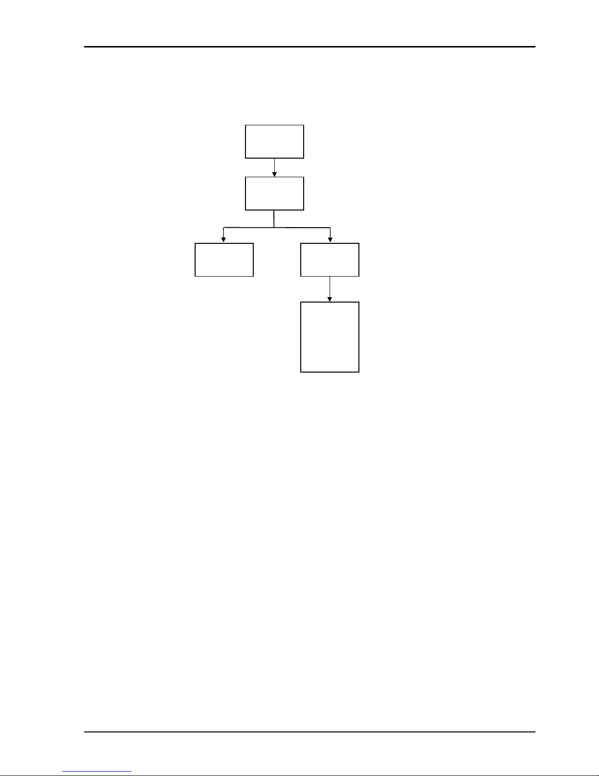
CPP100 SECTION 9
CPP1OPS 25/10/06 www.snellwilcox.com Version 1 Issue 6 9.7
Operation
Control parameters for the median filter can be found under the MEDIAN menu as shown below.
FILTERS
MEDIAN
MEDIAN LEVEL
Min1
Min 2
Med 3
Med 4
Max 5
Max 6

CPP100 SECTION 9
CPP1OPS 25/10/06 www.snellwilcox.com Version 1 Issue 6 9.8
Spatial Filtering
Spatial filtering typically involves using an aperture which comprises adjacent pixels from the same field period.
Typically linear filters have been used for noise reduction formed from a weighted average of adjacent pixels.
Usually non-adaptive in nature they reduce noise by averaging contributions across several pixels. In plain
areas, the degree of noise reduction is proportional to the sum of the square of the weighted contributions. In
general a larger aperture will allow a higher level of noise reduction.
Typical levels of noise reduction for equally weighted contributions are shown in the table below:
Aperture Size Noise power dB
3 -4.7
5 -6.9
7 -8.4
A major disadvantage of this approach is that high frequency picture detail is also filtered and this leads to a
softening of the picture on edges and on textures.
Spatial Aperture comprising adjacent points on the
same line and on adjacent lines above and below
the central pixel.
The spatial filter in PREFIX uses a median filter based on an aperture of 5 pixels shown above.
Median filters operate by rank ordering a set of points selected from a median aperture. The outer points end
up at the extremes of the list with the median value in the middle.
Although median filters can be effective at suppressing impulse they are also effective as gaussian noise
reduction filters.
The spatial filter operates by resolving the spatial median and then verifying if this is of similar value to the
current pixel. By varying the comparison threshold, the spatial filter can be tuned to reject noise but still
preserve picture transitions and textures.
The spatial filter is controlled by two settings that vary the comparison threshold and effectively set the balance
between the level of noise suppression and detail preservation.

CPP100 SECTION 9
CPP1OPS 25/10/06 www.snellwilcox.com Version 1 Issue 6 9.9
Spatial Filtering cont.
Operation
Control parameters for the spatial filter can be found under the SPATIAL menu as shown below:
The SPATIAL filter has separate controls for luminance and chrominance noise reduction levels.
Examples for use
The spatial filter is complementary to the temporal noise filters (such as recursive, de-enhancement and
decoder matching) and should be used in conjunction to achieve greater levels of noise suppression.
FILTERS
SPATIAL
SPATIAL LUMA CHROMA
Off
Min
Med
Max
Off
Min
Med
Max

CPP100 SECTION 9
CPP1OPS 25/10/06 www.snellwilcox.com Version 1 Issue 6 9.10
Linear Filters
Introduction
There are three types of linear filter which are available:
1. Brickwall Low Pass Filter with optional Boost
2. Gaussian Low Pass Filter.
3. Gaussian High Pass Filter.
The function of these filters is to perform various levels of noise reduction or compensation on the luminance
component of the video signal.
The requirement to filter the luminance component can be desirable since its high bandwidth means that it is
susceptible to high frequency noise. Also as the human eye is more susceptible to the luminance signal (as it
is this signal which controls picture contrast) filtering of the signal can be extremely important.
Brickwall Filter
This filter is employed to reduce noise resident in the high frequency region of the luminance spectrum.
The filter has two ranges: Low pass and Extra Low Pass
Low Pass.
There are 18 user selectable cut-off frequencies (specified at -6dB) ranging from 4.2 MHz down to 2.5 MHz in
0.1 MHz steps. The stopband performance is -34 dB or better with no boost.
In addition to the selectable cut-off frequencies the user can also select a given boost at each cut-off:
0dB (no boost), 1dB, 2dB, 3dB, 4.5dB, 6dB.
The boost value selected is the amount of gain applied to the filter response at the chosen cut-off frequency.
The selectable boost facility is incorporated to allow the user to increase the perception of sharpness in the
picture by boosting the contrast. The sharpness of a picture can sometimes be significantly reduced by filtering
the high luminance frequencies so the inclusion of the extra boost helps to restore some of the sharpness to
the picture. A boost of 6dB will result in the cut-off frequency being increased by up to 0.4 MHz.
The actual amount of boost selected will be a trade-off between cut-off and picture sharpness.
Extra Low Pass.
There are 6 user selectable cut-off frequencies (specified at -6dB) ranging from 2.4 MHz down to 0.9 MHz in
0.3 MHz steps. These filters can be used where the luminance component of the video signal needs to be
significantly reduced in bandwidth. This set of filters would only normally be used in exceptional circumstances.

CPP100 SECTION 9
CPP1OPS 25/10/06 www.snellwilcox.com Version 1 Issue 6 9.11
Linear Filters - cont.
0 1 2 3 4 5 6
Frequency (MHz)
Amplitude
2.8 MHz Brickwall Filter with available boosts
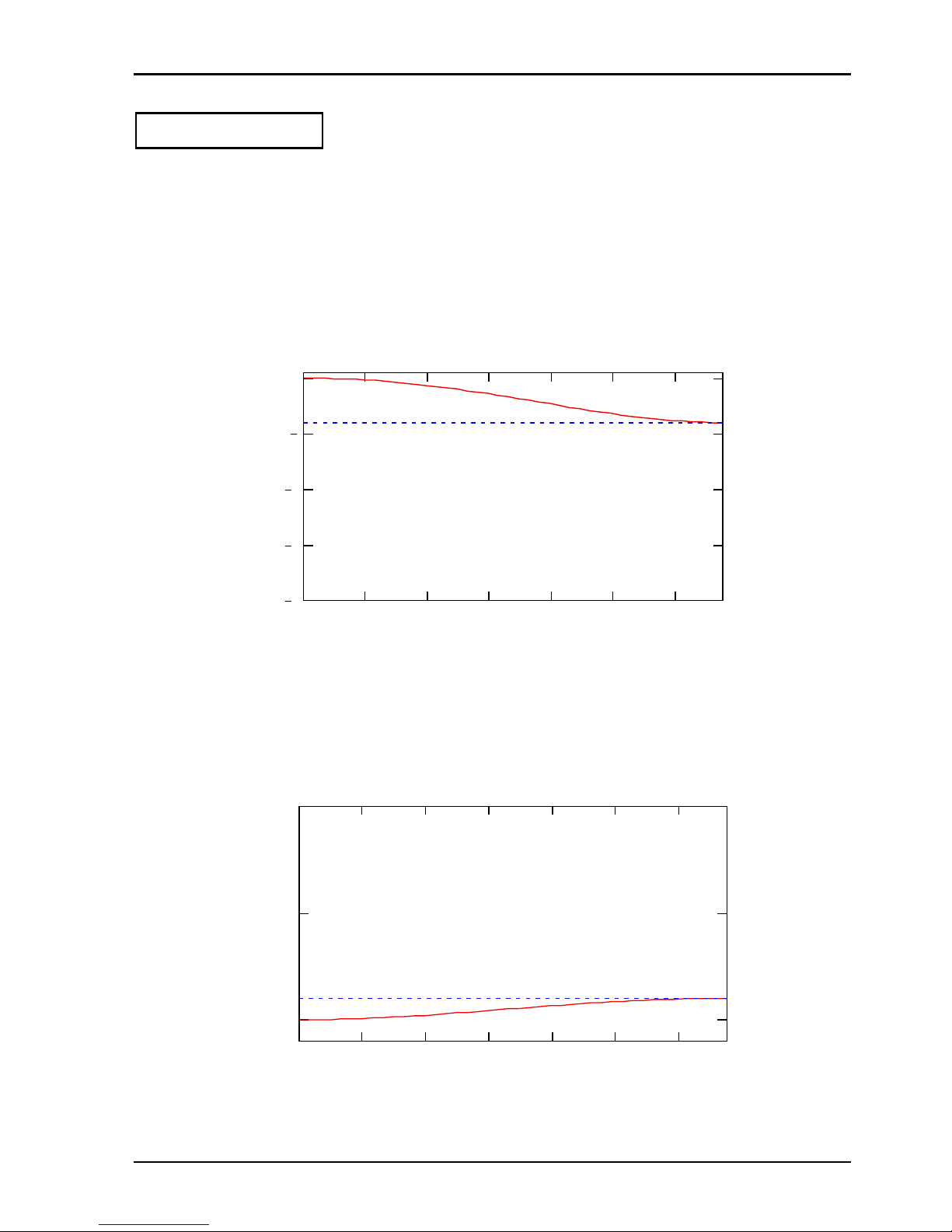
CPP100 SECTION 9
CPP1OPS 25/10/06 www.snellwilcox.com Version 1 Issue 6 9.12
Linear Filters - cont.
Gaussian Filter
This filter is employed for both noise reduction and compensation purposes. The filter has two user selectable
modes, both of which are mutually exclusive: low-pass and high-pass.
Gaussian Low Pass
The low-pass filter mode is employed to noise reduce with less severity than the brickwall filter and/or to
compensate for any irregularities in the luminance signal such as inherent high frequency gain.
This mode has 10 user selectable levels at 6.75 MHz ranging from -4dB to -40dB in -4dB steps.
0 1 2 3 4 5 6
20
15
10
5
0
Frequency (MHz)
Gain (dB)
Gaussian Low Pass Filter with -4dB Gain
Gaussian High Pass
The high-pass filter mode is employed to compensate for high frequency attenuation in the luminance
spectrum. This high frequency attenuation may be mainly caused by stray capacitance’s inherent throughout
the cables of an installation. This mode has 5 user selectable levels at 6.75 MHz: 1dB, 2dB, 3dB, 4.5dB, 6dB.
0 1 2 3 4 5 6
0
5
10
Frequency (MHz)
Gain (dB)
Gaussian High Pass Filter with 1 dB Gain

CPP100 SECTION 9
CPP1OPS 25/10/06 www.snellwilcox.com Version 1 Issue 6 9.13
Linear Filters - cont.
Operation
The linear filter control parameters can be found in the FILTERS menu under LINEAR.
The control features available to the user depend on the filter mode selected.
The options available for each mode are as follows:
Mode - Off (Full Bandwith)
Mode - Brickwall
LINEAR
Mode
Cut-Off
Boost
Low Pass
Extra
Low Pass
4.2 Mhz
4.1 MHz
4.0 MHz
3.9 MHz
3.8 MHz
3.7 Mhz
3.6 MHz
3.5 MHz
3.4 MHz
3.3 MHz
3.2 MHz
3.1 MHz
3.0 MHz
2.9 MHz
2.8 MHz
2.7 MHz
2.6 MHz
2.5 MHz
2.4 Mhz
2.1 MHz
1.8 MHz
1.5 MHz
1.2 MHz
0.9 MHz
0 dB
1 dB
2 dB
3 dB
4.5 dB
6 dB
Brickwall
Gaussian LP
Gaussian HP
Off
LINEAR
Mode
Off
Gaussian LP
Gaussian HP
Brickwall

CPP100 SECTION 9
CPP1OPS 25/10/06 www.snellwilcox.com Version 1 Issue 6 9.14
Linear Filters - cont.
Mode - Gaussian Low Pass
Mode - Gaussian High Pass
The factory default setting for the linear filter is Off (Full Bandwidth).
The factory default settings for each filter type are as follows:
Brickwall 4.2 MHz (0 dB Boost)
Gaussian LP -4 dB
Gaussian HP 1 dB
LINEAR
Off
Brickwall
Gaussian HP
Gaussian LP
Mode
Gain
-4 dB
-8 dB
-12 dB
-16 dB
-20 dB
-24 dB
-28 dB
-32 dB
-36 dB
-40 dB
Off
Brickwall
Gaussian LP
Gaussian HP
LINEAR
Mode
Gain
1 dB
2 dB
3 dB
4.5 dB
6 dB

CPP100 SECTION 9
CPP1OPS 25/10/06 www.snellwilcox.com Version 1 Issue 6 9.15
Scratch Filter
Introduction
This filter has been designed to detect and repair vertical scratches, of variable contrast and length, be they
black, white or both, while maintaining picture quality where there are no scratches. To maximise the benefit
obtained from this filter, a suite of filter strengths has been provided.
Operation
Control parameters for the scratch filter can be found under the SCRATCH menu as shown below:
Scratch Filter - On/Off
For unscratched material, it makes sense to turn the scratch filter off.
In order to remove scratches, it is necessary to enable the scratch filter.
Strength
There are three Filter Strengths available, and they are denoted as Min, Med and Max.
By increasing the strength of the filter, the potential for detecting and removing more scratches is improved.
While the probability of false alarms is small, increasing the filter strength increases the probability of false
alarms. Thus, when choosing the filter strength for a certain piece of footage, the smallest filter strength that is
sufficient to cope with its scratches should be chosen, thus minimising the number of unrepaired scratches as
well as false alarms, while maintaining maximum picture quality.
FILTERS
SCRATCH
TYPESTRENGTHSCRATCH CONTRAST
LENGTH
Any
Long
Low
Med
High
Min
Med
Max
Both
White
Black

CPP100 SECTION 9
CPP1OPS 25/10/06 www.snellwilcox.com Version 1 Issue 6 9.16
Contrast
There are three settings for Scratch Contrast available, and they are denoted as Low, Med and High.
Depending on the footage in question, the scratches may be low, medium or high contrast. Selecting the most
appropriate Scratch Contrast option results in the maximum number of detected scratches, the minimum
number of undetected scratches and the minimum number of false alarms, while keeping picture quality to its
maximum.
Type
With most pieces of footage, the scratches appear to be white or black. With footage that has been processed
both as positives and negatives, there may be both white and black scratches present.
Where there is only one type of scratch (i.e. white or black), the Type option should be set to White or Black,
as appropriate. This will aid in reducing the number of false alarms, and thus result in improved picture quality.
Where there are white and black scratches, the Type option should be set to Both.
Length
As well as being of different strength, type and contrast, scratches will also be of different lengths.
Where one is only concerned with repairing long scratches (whose length is the majority of the height of the
screen), the Length option should be set to Long. This will result in the minimum number of false alarms, while
keeping picture quality to its maximum.
When concerned with short scratches, or scratches of any length, the Length option should be set to Any.
Width
As well as being of different strength, type, length and contrast, scratches will also be of different widths.
Selections available are Narrow or Wide.

CPP100 SECTION 9
CPP1OPS 25/10/06 www.snellwilcox.com Version 1 Issue 6 9.17
Enhancer
Introduction
The enhancer has four distinct modes of operation that can be used individually to improve picture quality in
four unique ways. These are: Enhance, MPEG De-enhance, Decoder Matching & Video mode.
Mode - Enhancement
During the process of video recording or transmission, pictures can lose sharpness as high frequency
components of the picture are lost or reduced, resulting in soft or blurred edges.
The aim of the enhancer is to restore the perceived sharpness of an image by adding a correction signal
derived from information from the incoming signal to sharpen edges and boost peaks but in a way that does
not produce unnaturally sharp pictures or excessive unwanted artefacts.
The enhancer correction signal uses a combination of linear and non-linear methods. The linear and non-linear
enhancement signals are calculated separately and combined to provide the final correction signal which is
then summed with the incoming signal.
Non-linear enhancement is able to enhance images without the large increase in overshoots and ringing that
are associated with linear enhancement methods.
The non-linear correction signal consists of a peak enhancement signal and an edge enhancement signal. The
type of non-linear enhancement is determined by analysis of the incoming signal and has a pixel by pixel
response to provide the optimum blend of peaking and edge correction.
Although the benefits of linear enhancement methods are limited, linear enhancement is more successful at
dealing with low amplitude detail and texture in pictures.
The enhancer uses a combination of both methods to provide an optimum correction signal that produces
minimal ringing and overshoots.
The control of enhancement levels together with the adjustable coring make the enhancer a very powerful tool
for improving picture quality.
As mentioned previously the aim of the enhancer is to sharpen edges and boost peaks with minimal ringing
and overshoots. An example of this is shown below. This shows the output of a conventional enhancer
showing large undershoots and overshoots. The dotted line represents the enhanced signal and the solid line
shows the input signal.
Conventional enhancement

CPP100 SECTION 9
CPP1OPS 25/10/06 www.snellwilcox.com Version 1 Issue 6 9.18
Enhancer cont.
The figure below shows the output of the enhancer. The solid line shows the enhanced signal and the dotted
line shows the input signal. The rise and fall time of the edges has been reduced i.e. the edges are sharper
without changing the position of the edge. The peak has been boosted which will also add to the appearance
of a sharper picture.
Enhancer output
The enhancer uses two different types of filtering in order to optimise the type and level of enhancement. The
two filters used are a broad bandpass filter and an adaptive filter.
The broad bandpass filter produces the highest enhancement levels at
3.375 MHz for luminance whereas the adaptive filter has the highest levels of enhancement over a broader
range of frequencies.
The table below shows the filter settings used for the various levels of luminance enhancement:
Enhance Level Filter Type
minimum broad bandpass
medium broad bandpass
maximum adaptive
Coring
The aim of coring is to reduce or prevent the enhancement of noise in the picture using information from the
incoming signal. The coring function uses an adjustable threshold window that can be adjusted for different
levels of noise in the incoming signal. The enhancer has adjustable coring levels that can be altered depending
on the quality of input pictures. The higher the coring level the less noise is enhanced.
 Loading...