


ARC130S 060801 Version 1 Issue 1 0.1
Operator’s
Manual
© August 2001
Snell & Wilcox Ltd, Durford Mill, Petersfield, Hampshire, GU31 5AZ, United Kingdom.
Tel: +44(0) 1730 821188. Fax: +44(0) 1730 821199.
ARC130S
Aspect Ratio Converter

ARC130S SECTION 0
ARC130S 060801 Version 1 Issue 1 0.2
Safety Warnings
Always ensure that the unit is properly earthed and power connections correctly made.
This equipment shall be supplied from a power system providing a PROTECTIVE EARTH
connection and
having a neutral connection which can be reliably identified.
The power terminals of the IEC mains input connector on the rear panel are
identified as shown below:
E = Protective Earth Conductor
N = Neutral Conductor
L = Live Conductor
Power cable supplied for countries other than the USA
The equipment is normally shipped with a power cable with a standard IEC moulded free socket on one end
and a standard IEC moulded plug on the other. If you are required to remove the moulded mains supply plug,
dispose of the plug immediately in a safe manner. The colour code for the lead is as follows:
GREEN/YELLOW lead connected to E (Protective Earth Conductor)
BLUE lead connected to N (Neutral Conductor)
BROWN lead connected to L (Live Conductor)
Power cable supplied for the USA
The equipment is shipped with a power cord with a standard IEC moulded free socket on one end and a
standard 3-pin plug on the other. If you are required to remove the moulded mains supply plug, dispose of the
plug immediately in a safe manner. The colour code for the lead is as follows:
GREEN lead connected to E (Protective Earth Conductor)
WHITE lead connected to N (Neutral Conductor)
BLACK lead connected to L (Live Conductor)
The terminals of the IEC mains supply
lead are identified as shown opposite:
Note that for equipment that is not fitted with a mains power switch, to comply with BS60950 Clauses 1.7.2 and
2.6.9, the power outlet supplying power to the unit should be close to the unit and easily accessible.
Warnings
Voltages within this unit can be lethal under certain circumstances. Where power
is required to be connected to the unit during servicing great care must be taken
to avoid contact with these voltages.
Maintenance should only be carried out by suitably qualified personnel.
No part of this publication may be transmitted or reproduced in any form or by any means, electronic or
mechanical, including photocopy, recording or any information storage and retrieval system, without
permission being granted, in writing, by the publishers or their authorised agents.

ARC130S SECTION 0
ARC130S 060801 Version 1 Issue 1 0.3
EMC Standards
This unit conforms to the following standards:
Electromagnetic Compatibility-Generic Immunity Standard BS EN 50082-1:1992
The European Standard EN 50082-1:1992 has the status of a British Standard and is related to European
Council Directive 89/336/EEC dated 3rd May 1989.
Electromagnetic Compatibility-Generic Emission Standard BS EN 50081-1:1992
The European Standard EN 50081-1:1992 has the status of a British Standard and is related to European
Council Directive 89/336/EEC dated 3rd May 1989.
Federal Communications Commission Rules Part 15, Class A :1998
Safety Standards
This unit conforms to EN60065:1992 as amended by amendment A1(May 1993) and
amendment A2(March 1994). Specification for safety of technology equipment, including
electrical business equipment.
EMC Performance of Cables and Connectors
Snell & Wilcox products are designed to meet or exceed the requirements of the appropriate European EMC
standards. In order to achieve this performance in real installations it is essential to use cables and connectors
with good EMC characteristics.
All signal connections (including remote control connections) shall be made with screened cables terminated
in connectors having a metal shell. The cable screen shall have a large-area contact with the metal shell.
COAXIAL CABLES
Coaxial cables connections (particularly serial digital video connections) shall be made with high-quality
double-screened coaxial cables such as Belden 8281 or BBC type PSF1/2M.
D-TYPE CONNECTORS
D-type connectors shall have metal shells making good RF contact with the cable screen. Connectors having
"dimples" which improve the contact between the plug and socket shells, are recommended.

ARC130S SECTION 0
ARC130S 060801 Version 1 Issue 1 0.4
About this Manual
This manual covers the following product:
• ARC130S with 8 GPI inputs (via 2 x 9 way D connectors) and 8 GPI outputs via a 25 way D connector
Packing List
The unit is supplied in a dedicated packing carton provided by the manufacturer and should not be accepted if
delivered in inferior or unauthorised materials. Carefully unpack the carton and check for any shipping damage
or shortages.
Any shortages or damage should be reported to the supplier immediately.
Enclosures:
• ARC 130S Aspect Ratio Converter
• Power cable
• Operators Manual
• 2 floppy disks containing software for up and down loading ARC configurations to a PC
Software Version Amendments
Notes about Versions Fitted
Firmware. This machine is shipped with version A32 of the firmware.
Floppy Discs Disk 1 ARC Configuration Loader Version 1.0.1
Disk 2 ARC Configuration Loader Version 1.0.1
Manufacturers Notice
Copyright protection claimed includes all forms and matters of copyrightable material and information now
allowed by statutory or judicial law or hereinafter granted, including without limitation, material generated from
the software programs which are displayed on the screen such as icons, screen display looks etc.
Reproduction or disassembly of embedded computer programs or algorithms prohibited.
Copyrighted names:
Microsoft Windows™
Information in this manual and software are subject to change without notice and does not represent a
commitment on the part of Snell & Wilcox Ltd. The software described in this manual is furnished under a
licence agreement and may not be reproduced or copied in any manner without prior agreement with Snell &
Wilcox Ltd. or their authorised agents.

ARC130S SECTION 0
ARC130S 060801 Version 1 Issue 1 0.5
Table of Contents
Section 1 Introduction
Section 2 Specification
Section 3 Installation
Power Connections .......................................................................................................... 3.1
Environment .....................................................................................................................3.1
Rear Panel Connections .................................................................................................. 3.2
Using a Kudos Active Front Panel fitted to a Shoebox..................................................... 3.5
GPI Connections .............................................................................................................. 3.6
ARC Configuration Loader Program ................................................................................ 3.8
Switching On ....................................................................................................................3.10
Section 4 Operation
Introduction....................................................................................................................... 4.1
Switch Controls (Blank Front Panel) ................................................................................ 4.1
Top Menu ............................................................................................................... 4.2
Audio ...................................................................................................................... 4.3
Blanking ................................................................................................................. 4.4
Display ................................................................................................................... 4.5
GPI ......................................................................................................................... 4.10
Auto Setup ............................................................................................................. 4.11
Line 23 (PAL Standard Only) ................................................................................. 4.14
AFD Dat ................................................................................................................. 4.15
Memory .................................................................................................................. 4.17
Setup...................................................................................................................... 4.18
VITS ....................................................................................................................... 4.23
Option with Front Panel Controls ..................................................................................... 4.24
Function Select ...................................................................................................... 4.25
Display ................................................................................................................... 4.25
VITS ....................................................................................................................... 4.27
Auto........................................................................................................................ 4.27
Setup...................................................................................................................... 4.28
GPI ......................................................................................................................... 4.30
Bypass ................................................................................................................... 4.36
User........................................................................................................................ 4.36
Aspect Ratio Selection ........................................................................................... 4.37
Blanking Setup ....................................................................................................... 4.46
Line 23 Setup ......................................................................................................... 4.47
Video Index Setup.................................................................................................. 4.48
Appendix – Video Index and Enhanced Line 23 .................................................... 4.50
Operation via a Kudos Active Front Panel
Protocol .................................................................................................................. 4.53
RollCall Menu System Drawing.............................................................................. 4.54
Menu Details .......................................................................................................... 4.55
Section 5 System Overview ........................................................................................................... 5.1
Block Diagram Description ............................................................................................... 5.2
Section 6 Aspect Ratio Technical Codes for Video and Picture Sources

ARC130S SECTION 0
ARC130S 060801 Version 1 Issue 1 0.6
Manual Revision Record
Date Version No. Issue No. Change Comments
060801 1 1 First issue of manual

ARC130S SECTION 1
Introduction
ARC130S 060801 Version 1 Issue 1 1.1
Aspect Ratio Converter ARC130S
Front Panel View
INPUT
SERIAL DIGITAL
MADE IN ENGLAND
REMOTE
CONTROL
DELAY
1
ACTIVE
LOOP
OUTPUT
SERIAL DIGITAL
12
AC INPUT
AUTO SELECT
115/230V
1.2/0.6A
45-60Hz
FUSE
T2.5A
ROLLCALL
RS-422
EDH GP I OUT GPI IN
11
2
MMMMooooddddeeeellll:::: AAAARRRRCCCC 111133330000SSSS SSSSeeeerrrriiiiaaaallll NNNNoooo....
Rear Panel View
The ARC130S is a compact Broadcast-Quality
Aspect Ratio Converter with serial digital inputs
and outputs. It will aspect ratio convert in both
directions, e.g. 16:9 to 4:3 or 4:3 to 16:9, and
allows the picture area required for transmission to
be selected from the input picture.
There are twelve preset conversion ratios plus
ratios set up by the user. The user ratios can be
stored in twelve memories and are quickly
pushbutton selected when required for use.
The aspect ratio can also be remotely controlled
either via an RS-422 port, RollCall or from contact
closures via a General Purpose Interface (GPI).
The ARC130S is designed to fit in Continuity
Suites, Studio’s, Outside Broadcast Vans, etc.
It facilitates the production of master tapes for
broadcast using PAL+, D2MAC and digital
transmissions. It facilitates postproduction and
presentation of tapes mastered in 16:9 format
through the current 4:3 format transmission
system.
The ARC130S is a compact 1RU high unit for
location on the desktop or in a 19-in. rack. It will
operate in 525 and 625 line systems.
Vertical interval information is passed without
conversion.

ARC130S SECTION 2
ARC123S 060801 Version 1 Issue 1 2.1
Specifications
Features
Signal Inputs
Serial Digital 1 Serial D1 525 or 625 via BNC
loop-through connectors
Remote Control 9 way D-Type
GPI 2 via 9 way D-Type
Network Control RollCall via BNC connector
Signal Outputs
Serial 2 sets of Serial Digital D1 via BNC
connectors
Delay 1 Output via BNC connector
GPI via 25 way D-Type
Control
Functions
Blanking: Controls blank i ng on bot h i nput
and output
Display Position, Size and Aspect Ratio
Enhanced Line 23
Setup
Input/Output Setup
Video Index Input/Output Setup
Memory Stores settings in m em o ry and
allows recall of memorized
settings
VITS VITS blanking
SETUP Audio, Clipping, Freeze, Gamut
Limiting, GPI, GPI P rogram , Input
Loss, Input Standard (625, 525),
Process, Test Pattern, Field
Pairing Mode and line 21 video
(525 line systems).
BYPASS Non-interpolated output
USER User display memories
Output Aspect Ratio Letterbox: 16:9, 1.85:1, 1.66:1,
14:9.
Full Screen: 16:9, 1.85:1, 1.66:1,
16:9 anamorphic
4:3 Curtains, 14:9 Curtains, 4:3
Full Width, 16:9 full Width
Specifications
Input Standard 525/625 line
Serial Input Return
Loss
better than 15 dB to 270 MHz
Serial Output Return
Loss
better than 15 dB to 270 MHz
Power
Input Voltage Range 90 V to 260 V 45/90 Hz
Consumption 75 W maximum
Mains Fuse Rating 2.5 AT
Mechanical
Temperature Range 0 to 40° C operating
Case Type 1U Rack Mounting
Dimensions 483 mm x 530 m m x 44 mm
(w,d,h)
Weight 7 kg

ARC130S SECTION 3
Installation
ARC130S 060801 Version 1 Issue 1 3.1
POWER CONNECTIONS
Power Supply
Mains power is supplied to the unit via a filtered
IEC connector with integral fuse holder. The fuse
rating is 2.5 A (T).
The unit automatically senses the supply voltage in
the ranges 90V-132V and 176V-264V and sets
itself up accordingly. No voltage adjustment
procedure is required.
ENVIRONMENT
The unit is ruggedly constructed to meet the
normal environmental requirements. It is important
that there is a free flow of air at both sides of the
unit to dissipate the heat produced during
operation. Installations should be designed to allow
for this.
If the unit is to be rack mounted, first open the front
panel by lifting up the the two levers at right and left
of the panel, hinge the panel down and
AC INPUT
AUTO SELECT
115/230V
1.2/0.6A
45-60Hz
FUSE
T2.5A
pull it forward. The fixing “ears” behind the panel
will be revealed and the unit can be mounted in the
rack. Refit or close the front panel by pushing it
back into position (the levers will click into place).
The rear of the base includes additional fixing
holes on either side to allow a rear support to be
added.

ARC130S SECTION 3
Installation
ARC130S 060801 Version 1 Issue 1 3.2
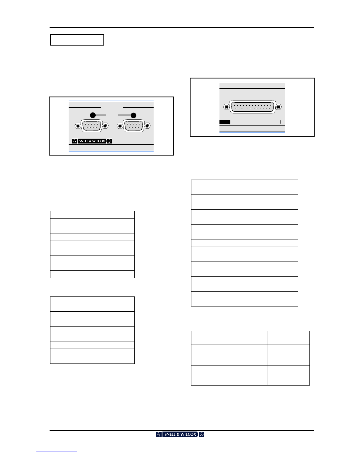
REAR PANEL CONNECTIONS
Digital Input
A BNC connector is provided for the serial digital
input, with an active loop-though BNC connector
also fitted.
Digital Output
Two BNC connectors are provided for the serial
digital outputs.
EDH
This connector has no function; connections
should not be made to this connector.
INPUT
SERIAL DIGITAL
ACTIVE
LOOP
1
OUTPUT
SERIAL DIGITAL
12
EDH
MMMMooooddddeeeellll:::: AAAARRRRCCCC

ARC130S SECTION 3
Installation
ARC130S 060801 Version 1 Issue 1 3.3
Delay Output
Because the ARC130S contains a synchroniser,
the through delay depends upon the setting of
vertical genlock timing.
If the input and output video are co-timed, then the
delay through the ARC130S is four fields (80 ms
for 625 line systems and 66.7 ms for 525 line
systems). If the input and output video are not cotimed then the range of delay through the ARC is
3.5 to 4.5 fields.
The delay pulse output from the ARC130S
accurately represents the delay through the unit.
The pulse is high for a period equal to the delay
through the ARC. It can be connected to a Snell
and Wilcox audio delay module to automatically set
a compensating audio delay.
If the ARC130S is put into Bypass mode or, field
pairing mode, then the nominal delay remains at
four fields. However because the unit acts as a
frame synchroniser in these modes, the delay
range of the unit is now increased to between 3
and 5 fields.
DELAY

ARC130S SECTION 3
Installation
ARC130S 060801 Version 1 Issue 1 3.4
Remote Control
The unit can be controlled from the special remote
panel option via an RS-422-A D-type connector
(see Table - RS-422-A Remote Connections)
If a remote panel is connected to the RS-422-A
port, set the “Front Panel/Remote Comms/
Auxiliary switch on the ARCOPI2A card to “FRP &
REM” (centre), see Fig. 3.1
The front panel can be disabled by setting the
switch to REM (right hand position) see Fig. 3.1
RS-422-A Remote (Master) Connections
Pin Function Direction
1
2
3
4
5
6
7
8
9
Ground
Transmit –
Receive +
Rec Sig Common
Spare
Trans Sig Common
Transmit +
Receive –
Ground
ARC Remote
ARC çRemote
ARC Remote
ARC çRemote
The Baud Rate is 38.4Kbs, half duplex. Format is 1
start bit, 7 data bits, 1 parity bit, 1 stop bit.

ARC130S SECTION 3
Installation
ARC130S 060801 Version 1 Issue 1 3.5
OPERATION FROM A KUDOS ACTIVE FRONT PANEL FITTED TO A SHOEBOX
OPERATIONAL OVERVIEW
The ARC130S has provision to be remotely
controlled via two different interfaces, either S&W
RollCall, or RS422.
Interface to the "RollCall" communications network
is via the single BNC connector. Connections
should be made by means of a `T' piece (Zo=75
Ohms) to a 75 Ohm cable system as shown below.
It should be noted that both extremities of the cable
system must be terminated in 75 Ohms and the
maximum number of units limited to 240 on one
single cable run.
The communications network is a specially
designed remote control network system and many
more units can be accommodated by using a
"Network Bridge". Remote control can come from
either a dedicated front panel or "shoe-box" or a
standard IBM compatible PC. Full protocol
documentation and more detailed information is
available on request from the supplier.
The RS 422 remote control interface is via the 9pin female `D' connector. Protocol information is
also available on request from the supplier.
For more detailed information about the operation
of the remote panel or PC software please consult
their relevant manuals. e.g. Shoebox operator’s
manual.
For specific information about the RollCall menu
system for the ARC130S see Section 4, Operation,
RollCall Menu System on page 4.34
BASIC ROLLCALL OPERATION
All the features from the menu system are
available remotely with the same options structure.
This maintains compatibility and facilitates easy
operation for users familiar with the unit.
The most common remote configuration is shown
below where many units are connected to the
network for remote control by one remote panel or
"shoe-box".
Typical Set-up
The network address for the ARC is set using the
switches SW3 and SW 4 on the Output Interface
card. See fig 3.1 on page 3.8.
Parameter changes are reflected both locally and
remotely. For example, if the output is changed to
the colour bars test pattern by a remote unit then
any further access from the card edge to the
PATTERN TYPE option will indicate this change.
Similarly, if the card edge changes a parameter
then this will be reflected on the display panel of
the remote unit.
ARC130S SECTION 3
Installation
ARC130S 060801 Version 1 Issue 1 3.6
GPI
GPI functions are implemented as follows:
GPI Inputs
MADE IN ENGLAND
CONTROL
GPI IN
11
2
These are accessed via two 9-way D type
connectors labelled 1 and 2. Each connector has 4
inputs and connections are as below.
GPI = GPI input
GPI input 1
Pin 2 GPI 0 signal
Pin 6 GPI 0 return
Pin 3 GPI 1 signal
Pin 7 GPI 1 return
Pin 4 GPI 2 signal
Pin 8 GPI 2 return
Pin 5 GPI 3 signal
Pin 9 GPI 3 return
Pin 1 safety ground.
GPI input 2
Pin 2 GPI 4 signal
Pin 6 GPI 4 return
Pin 3 GPI 5 signal
Pin 7 GPI 5 return
Pin 4 GPI 6 signal
Pin 8 GPI 6 return
Pin 5 GPI 7 signal
Pin 9 GPI 7 return
Pin 1 ground.
GPI Outputs
GPI OUT
111133330000SSSS SSSSeeeerrrriiiiaaaallll NNNNoooo....
These are accessed via a 25-way D type connector
and connections are as follows:
GPO = GPI output
Pin 2 GPO 0 signal
Pin 14 GPO 0 return
Pin 3 GPO 1 signal
Pin 15 GPO 1 return
Pin 4 GPO 2 signal
Pin 16 GPO 2 return
Pin 5 GPO 3 signal
Pin 17 GPO 3 return
Pin 6 GPO 4 signal
Pin 18 GPO 4 return
Pin 7 GPO 5 signal
Pin 19 GPO 5 return
Pin 8 GPO 6 signal
Pin 20 GPO 6 return
Pin 9 GPO 7 signal
Pin 21 GPO 7 return
Pins 1,10,11,12,13,22,23,24,25 ground
The GPO output characteristics are as follows:
Operating Voltage Range 0 to ±60 V
(DC/AC peak)
Maximum Load current 1.0 A (AC/DC)
Maximum On-State
Resistance @ Tamb =+25°C
500 mOhm
Minimum Off-State
Resistance
@Tamb =+25°C,V=±48V
100 MOhm

ARC130S SECTION 3
Installation
ARC130S 060801 Version 1 Issue 1 3.7
GPI Overview
The GPO provides contact closure tally outputs
that can be used to turn on lamps etc.
GPO 0 tracks GPI 0 so if the display memory that
GPI 0 recalls is active then GPO 0 will close.
Similarly, GPO 1 tracks GPI 1 etc.
This functions even if the GPI inputs have been
assigned different recall memories and if the
memory was recalled via a front panel button
rather than via the GPI.
So, if GPI 3 recalls AUTO, then whenever AUTO is
selected GPO 3 will be closed.
In GPI binary mode, the four LSB’s (GPO 0 to
GPO 3) GPI contacts indicate the binary GPI
memory in use. The four MSB’s (GPO 4 to GPO 7)
contacts are closed if a GPI binary memory is
being used; otherwise they are open.
If a non-binary GPI memory is being used all 8
contacts will be open.
GPI interface Delay
The GPI interface on the ARC130S has a delay
that matches the video processing delay through
the ARC.
This means that if a given input-video field is
desired to produce the first output-field built with a
new aspect ratio conversion; the GPI contacts that
recall that new aspect ratio conversion should be
closed during the field when that video field is
present at the ARC130S input.
Ideally, the contact should be closed a few lines
after the vertical sync group of the reference video,
and, should remain closed for at least one field
period.

ARC130S SECTION 3
Installation
ARC130S 060801 Version 1 Issue 1 3.8
Included with ARC130S software version A32 are 2 floppy disks containing software for up and down
loading ARC configurations to a PC.
ARC Configuration Loader Program
The downloading and uploading of ARC
configuration files is made possible by the
Windows program ‘ARC Configuration Loader’.
Data contained in existing ARC configuration files
(held on the PC) may be downloaded to the ARC
or, ARC hardware configurations may be uploaded
to the PC. The configuration files held on the PC
are in a simple ASCII text format. The
configuration files contain all parameters held in
the ARC. This includes all display memories of all
types that the user can program. This allows the
user to configure an ARC once and then, send that
same configuration to multiple units. Also, if the
ARC software is upgraded, the user can store the
ARC configuration before the upgrade and then
download it afterwards so that the configuration
does not have to be re-done.
The ARC Loader program uses the ARC RollCall
network BNC connection. Thus, the user must
have a means of connecting to the ARC RollCall
BNC before the program can be used. Therefore a
RollCall ‘Shoebox’ or a PC equipped with the high
speed RollCall network card must be available.
The ARC loader program is designed to work with
ARC software version A28 and onwards. Note that
software versions A24 and onwards allow the user
to upload the configuration data from the ARC to
the PC but, the download operation can fail. This
will allow users of software versions A24 to A27 to
capture their ARC configurations before upgrading
to A28.
ARC Configuration Loader Installation
The distribution of the ARC Configuration Loader
includes a setup.exe program file. This file is kept
on the floppy disk labelled DISK1. Running the
ARC Configuration Loader setup.exe, either by
mouse click from within Windows Explorer, or from
the Windows Start\Run menu, will commence the
setup sequence. SETUP SHOULD ONLY BE RUN
LOCALLY TO THE TARGET HOST MACHINE,
this may be achieved either by installing locally
from floppy disk or, by copying the installation files
to a local, temporary directory and running setup
from there. The ARC Configuration Loader
requires the RollCall server program RollOLE to be
pre-installed. The ARC Configuration Loader setup
program searches for a registered installation of
RollOLE prior to commencing its own installation
sequence. If the RollOLE executable is found and
validated then ARC Configuration Loader will
install. Conversely, if setup is unable to find or
validate RollOLE.exe it will inform the operator of
the requirement to install, or re-install, RollOLE and
then setup will exit. The installation of RollOLE
should then be carried out before re-attempting to
run the ARC Configuration Loader setup program.
A compatibility issue has arisen in that RollOLE
makes use of Windows Dynamic Link Library (.dll)
files, the current RollOLE is compatible with the
Library files required to run Internet Explorer (IE)
4.0 or later. Earlier versions of RollOLE will not run
correctly on systems that have installed on them
IE4.0, conversely, the current version of RollOLE
cannot run using the .dll files found on a system
using IE3.x or earlier. The setup program will
therefore detect the absence of IE, or if present the
version of IE, and may accordingly give the
operator the option to continue to load the ARC
Configuration Loader, or exit if a configuration not
suited to RollOLE is detected. This is only an issue
for systems running Win95, as Win98 and
WinNT4.0 implicitly use IE4.0 or later.

ARC130S SECTION 3
Installation
ARC130S 060801 Version 1 Issue 1 3.9
ARC Configuration Loader Operation
The ARC Configuration Loader program can be
run by double clicking on it from Explorer or via the
START menu. W hen the program is run the User
needs to set two parameters and then up and
downloading may begin.
1. Configuration File Name
This is the name of the file on the PC that the user
wishes to access. If an Upload is undertaken then
the data from the ARC will be stored in this file. If a
Download is undertaken then data from this file will
be sent to the ARC. A valid filename must be
chosen before an Upload or Download can be
undertaken. Note, the file extension must be .TXT.
The filename can be typed in or, the Browse button
may be used to navigate to the desired file.
2. ARC Address
This allows the user to select which ARC on the
RollCall network the program will connect to. The
user must select an ARC before an Upload or
Download can be undertaken. The find module
button should be clicked to navigate to the desired
unit.
3. Download
Clicking this button will send a configuration file
from the PC to the chosen ARC.
4. Upload
Clicking this button will send configuration data
from the ARC to the selected PC file.
Program Menu Selections
The following Menu selections are available to
operators of the ARC Configuration Loader:
1. File: Exit
Ends the ARC Configuration Loader Program.
2. Help: About
Provides Information about the ARC Configuration
Loader including version data

ARC130S SECTION 3
Installation
ARC130S 060801 Version 1 Issue 1 3.10
SWITCHING ON
Check that power is connected to the unit and is
switched on. Open the front panel by pushing up
the levers at the ends of the panel, and hinging the
panel down and sliding partly out.
Set the switch on the Power Unit (see fig. 3.1) to
on. Check that the indicator lamp illuminates green
and the alpha-numeric display is active.
Fig. 3.1 PCB Locations ARC 130S
Front panel &
Remote Control
Remote
Control
SW4 SW3
FAN FAIL WARNING
If when the power is turned ON the power indicator is RED and the card edge alpha-numeric display on the
active front panel displays FAN FAIL message, the unit should be turned OFF as this indicates a failure of the
cooling fan which is located behind the power switch panel.

ARC130S SECTION 4
ARC130S 060801 Version 1 Issue 1 4.1
SWITCH CONTROLS
To gain access to the controls, open the front
panel by lifting up the levers at right and left of the
panel, hinge the panel down and pull it forward.
To provide a full range of functions with just 4
buttons and an 8-digit display, a menu system is
used.
During normal operation, the display slowly cycles
through the status of current operation (Home
Display). Typically these will be the line standard,
the aspect ratio, genlock status and pattern
generated if on.
The ENT (Enter) key interrupts the Home Display
and allows you to enter the menu structure. It is
also used to display a selected option. The and
keys enable you to scroll up and down through
the menu. The ESC (Escape) key returns you to
the previous menu level.
A “>“ at the right of an option on display indicates
that selecting the option (pressing ENT) will lead to
another menu level without changing a system
setting. If there is not a “>“ at the right, pressing
ENT will change the indicated system setting.
If the menu being displayed allows you to pick one
of a number of options, the currently selected
option is indicated by an “∗” (asterisk) at the left.
Pressing and simultaneously returns a
parameter to it’s preset value.
Pressing ENT and ESC simultaneously will return
you to the Home Display.
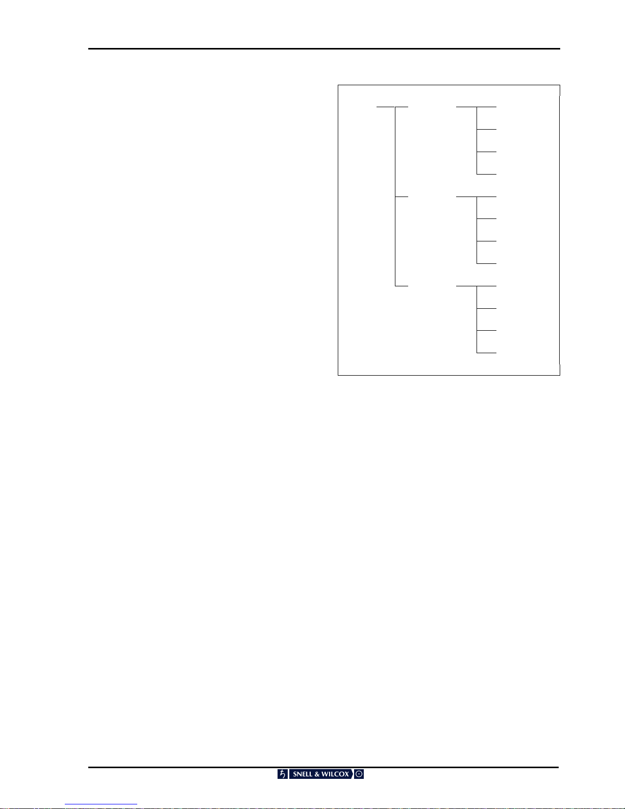
TOP MENU
Each of the items on the menu is described
separately.
Home Display
Audio
Blank (Blanking)
Display
Genlock
GPI
Auto
Memory
Setup
VITS
ARC130S SECTION 4
ARC130S 060801 Version 1 Issue 1 4.2
AUDIO
This allows the status of the audio channels to
beset up.
Use the I/P Group item to set the input group to 1,
3, or 4.
Use the O/P Group item to select the output group
to 1, 2, 3, or 4.
The embedded audio output may be set to Off (no
audio data), On (audio data from selected input
group), Mute (silence) or Test Tone.
An audio buffer compensates for the video delay.
Audio Setup Off
On
Mute
Tone
I/P Grp Group 1
Group 2
Group 3
Group 4
O/P Grp Group 1
Group 2
Group 3
Group 4

ARC130S SECTION 4
ARC130S 060801 Version 1 Issue 1 4.3
BLANKING
From the Home Screen, press ENT and scroll to
Blank. Press ENT and scroll between Input and
Output. Press ENT on the selected function.
Selecting Input allows you to adjust the input
blanking. Input blanking is used where the source
video applied is known to have pixels/lines at the
edge of the picture that you do not want to display.
The ARC130S will then blank any output data
which has been generated by that input data,
regardless of the display control settings.
Selecting Output is used where you do not want
the output to be active on more than a certain
range of output lines. For example you can impose
an artificial letterbox by bringing the top output
blanking down the screen and the bottom output
blanking up the screen.
Top: Adjusts the top line of blanking. 0 equals no
blanking on any output lines that would normally be
visible, 1 equals blank the first active line, etc.
Bottom: Adjusts the bottom line of blanking. 576
(PAL) or 486 (NTSC) equals no blanking on any
output lines that would normally be visible. 575
(PAL) or 485 (NTSC) equals blank the last active
line, etc.
Left: Adjusts the left-hand edge of blanking. 0
equals no blanking on any output pixels that would
normally be visible. 1 equals blank the first active
pixel.
Right: Adjusts the right-hand edge of blanking. 720
equals no blanking of any output pixels that would
normally be visible. 719 equals blank the last active
pixel.
ARC130S SECTION 4
ARC130S 060801 Version 1 Issue 1 4.4
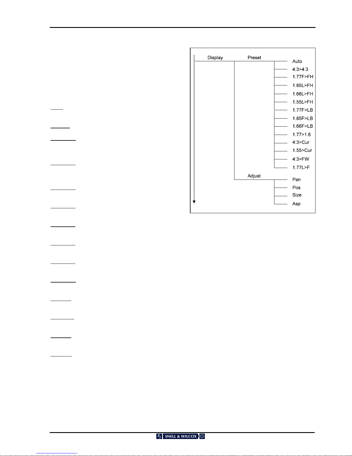
DISPLAY
From the Home Screen, press ENT and scroll to
Display. Press ENT and scroll between Preset and
Adjust. Press ENT on the selected function.
Preset allows selection of one of the preset aspect
ratio conversions. Adjust allows you to create your
own aspect ratio conversion.
Auto: Line 23 signalling or video index (PAL only) is
used to control the aspect ratio conversion.
4:3>4:3: No aspect ratio conversion.
1.77F>FH: 16:9 anamorphic to full height
conversion (left and right-hand edges of input
video lost).
1.85L>FH: 1.85:1 letterbox input to full height
conversion (left and right-hand edges of input
video lost).
1.66L>FH: 15:9 letterbox to full height conversion
(left and right-hand edges of input video lost).
1.55L>FH: 14.9 letterbox to full height conversion
(left and right-hand edges of input video lost).
1.77F>LB: 16:9 anamorphic to letterbox
conversion.
1.85F>LB: 1.85:1 anamorphic to letterbox
conversion.
1.66F>LB: 15:9 anamorphic to letterbox
conversion.
1.77>1.55: 16:9 anamorphic to 14:9 letterbox
conversion.
4:3>Cur: 4:3 to 16:9 curtains, i.e. horizontal crush
with black bars to left and right of output.
1.55>Cur: 14:9 to curtains, i.e. horizontal crush
with black bars to left and right of output.
4:3>FW: 4:3 to 16:9 full width conversion, i.e. top
and bottom of picture lost at the output.
1.77L>F: 16:9 letterbox to 16:9 anamorphic
conversion.
See next page for descriptions of the nomenclature
used for the above aspect ratio conversions.

ARC130S SECTION 4
ARC130S 060801 Version 1 Issue 1 4.5
CONVERSION DESCRIPTION NOMENCLATURE
Front panel*
Designation
BBC Notation* Full Description
Aspect
Value
Size
Value
1.77F>FH 16F16 > 12F12 16:9 Anamorphic picture to full height 4:3
picture for presentation on a 4:3 screen (left
hand and right hand edges of original 16:9
image are cropped
1.333 1.000
1.85L>FH 1.85:1 Letterbox picture to full height 4:3
picture with left hand and right hand edges of
original 1.85:1 image cropped
1.000 1.388
1.66L>FH 15L12 > 12F12 15:9 letterbox picture to full height 4:3 picture
with left hand and right hand edges of original
15:9 image cropped
1.000 1.250
1.55L>FH 14L12 > 12F12 14:9 letterbox picture to full height 4:3 picture
with left hand and right hand edges of original
14:9 image cropped
1.000 1.167
1.77F>LB 16F16 > 16L12 16:9 Anamorphic picture converted to 16:9
letterbox picture for presentation on 4:3 screen
(black bars above and below image)
1.333 0.750
1.85F>LB 1.85:1 Anamorphic picture converted to 1.85:1
letterbox picture for presentation on 4:3 screen
(black bars above and below image)
1.388 0.721
1.66F>LB 15F15 > 15L12 15:9 Anamorphic picture converted to 15:9
letterbox picture for presentation on 4:3 screen
(black bars above and below image)
1.250 0.800
1.77F>1.55L 16F16 > 14L12 16:9 Anamorphic picture converted to 14:9
letterbox picture for presentation on a 4:3
screen (black bars above and below image and
right hand and left hand edges of picture
slightly cropped)
1.333 0.857
4:3>Cur 12F12 > 12P16 4:3 image converted to 4:3 pillarbox/curtains
image in 16:9 anamorphic. (4:3 horizontally
squeezed image with black bars to left and
right of output)
0.750 1.000
1.55>Cur 14L12 > 14P16 14:9 letterbox picture in 4:3 converted to 14:9
pillar-box/curtains image in 16:9 anamorphic
(14:9 horizontally squeezed image with 1:9
black bars to left and right of output)
0.750 1.167
4:3>FW 4:3 image anamorphically squeezed and
scaled up to fill full 16:9 width. Top and bottom
of original 4:3 image cropped at output
0.750 1.333
1.77L>1.77F 16L12 > 16F16 16:9 letterbox in 4:3 converted to 16:9
anamorphic full height image
0.750 1.333
* For a detailed explanation of the these code specifications please refer to Section 6
“Aspect Ratio Technical Codes for Video and Picture Sources”

ARC130S SECTION 4
ARC130S 060801 Version 1 Issue 1 4.6
Pan: adjusts the horizontal position of the output.
Note that this option does not appear if V only
processing is selected.
(see set-up menu page 4.11)
Pos: adjusts the vertical position of the output.
Note that this option does not appear if H only
processing is selected.
(see set-up menu page 4.11)
Size: Adjusts the horizontal and vertical size
simultaneously while maintaining the aspect ratio.
The product of SIZ and ASP is limited to the range
0.50 to 2.00, and SIZ is limited to the range 0.50 to
2.00.
Note that this option does not appear if H only
processing is selected.
(see set-up menu page 4.11)

ARC130S SECTION 4
ARC130S 060801 Version 1 Issue 1 4.7
Asp: Adjusts the horizontal size of the output, so
changing the aspect ratio. The product of SIZ and
ASP is limited to the range 0.50 to 2.00, and ASP
is limited to the range 0.25 to 2.00.
Note that this option does not appear if V only
processing is selected.
(see set-up menu page 4.11)
GENLOCK
Selects adjustment of the Genlock parameters.
From the Home Screen, press ENT and scroll to
Genlock. Press ENT and scroll between H Time
and V Time. Press ENT on the selected function.
The ARC130S will always lock to the incoming
video.
H Time allows you to adjust the horizontal Genlock
timing with respect to the reference, in pixels.
V Time allows you to adjust the vertical Genlock
timing with respect to the reference, in lines.
ARC130S SECTION 4
ARC130S 060801 Version 1 Issue 1 4.8
GPI
This allows you to select GPI inputs On, Off,
On+Auto and Binary.
Off
The GPI function is inactive.
On
The GPI function is active. (One contact closure
per memory recall)
On+Auto
The GPI function is active. (One contact closure
per memory and all four contact closures turns on
Auto mode)
Note In order that the GPI contacts may be
released without the unit reverting to another GPI
memory recall, it is necessary that all four GPI
contacts are open for at least one field after Auto
has been selected using the GPI. Operation of the
GPI is suspended until this condition has been
met.
Binary
When the GPI input is put into binary mode the
four GPI inputs are treated as one four bit number.
This means that there are sixteen possible GPI
input states. Each of the GPI input-states recalls a
special GPI memory. These memories store the
same parameters as the User Display memories
and the Auto (video index / line 23) memories.
Thus one should set up the machine as required
(size, asp, pan, pos, bypass and output aspect
ratio signaling parameters) then, one can program
the required GPI memory. When that particular
GPI state is present the appropriate memory is
recalled.
This is useful as the GPI port can be used to
emulate the four video index signaling bits if they
are not present on the input signal.
GPI Mem
This lets you program the binary GPI memories. If
you select this, the display shows:
GPI 0
Pressing the arrow keys cycles through GPI 1 ,
GPI 2.......GPI 15.
You can then store the GPI memory settings for
the indicated binary GPI memory.
GPI GPI In Off
On
On+Auto
Binary
GPI Mem GPI 0…
…GPI 15
GPI Out Off
On
Invert
Assign GPI 0…
…GPI 15
Using the cardedge and active front panel menus
an extra item will appear when an 8-way GPI board
is detected.
This is GPI Out This allows the GPO to be turned
OFF, (all contacts open), turn it ON (default
setting) or turn it ON but work inverted (i.e. contact
open to indicate active memory).
The menu text is GPI Out - Off
On
Invert
Version A20 of the software will let you assign the
GPI’s from the cardedge controls as well as from
the active front panel and RollCall.
It has 8 entries (if 8 GPI inputs are available or 4 if
only 4 inputs are available) and the menu reads:
GPI 0 GPI 0
to OR to
GPI GPI 3
The assignment operates in the same way as
using the active front panel menu. That is, set the
ARC to recall the required display memory and
then assign the GPI to it.
By default GPI’s 0 to 7 recall user memories 1 to 8
respectively.
ARC130S SECTION 4
ARC130S 060801 Version 1 Issue 1 4.9
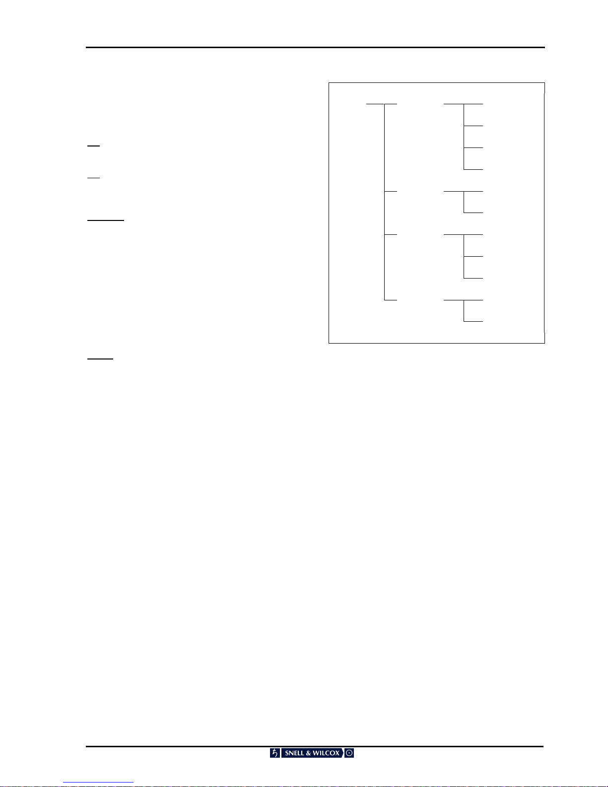
AUTO
This allows the user to control the action of the
ARC130S in the presence of an incoming Line 23
aspect ratio or video index signal. From the Home
Screen, press ENT and scroll to Auto.
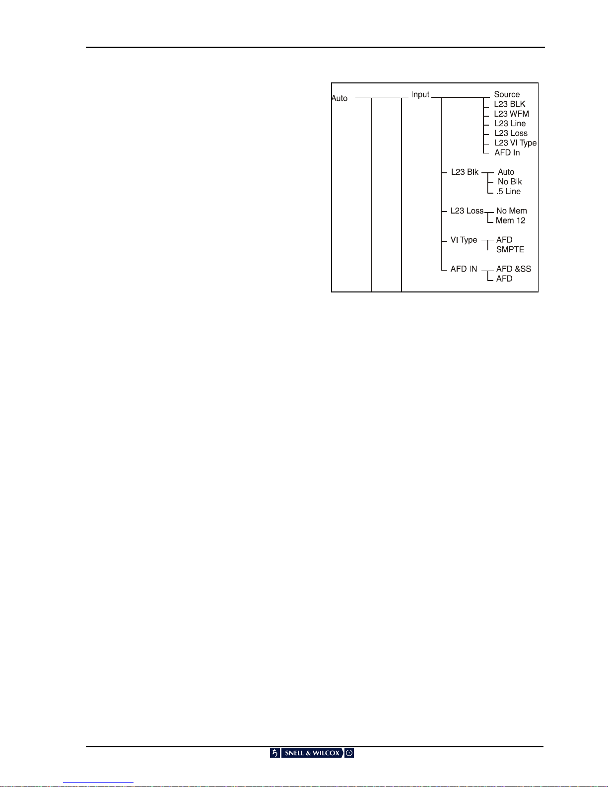
Input
This function allows the following selections to be
made to the input setup:
Source
This allows the source of automatic aspect ratio
control to be selected from the following:
L23 ETSI
L23 AFD
Video Ind
L23 Blk
This sets the blanking action applied to line 23.
There are three options.
Auto The machine will either automatically
provide the appropriate output
signalling blanking using the input
signalling
Not Blk The input signalling will not be blanked
.5 Line The first half line of the line 23
signalling will be blanked
L23 WFM
This gives you a choice of Normal or Non-Std.
Normal should be selected for all legal incoming
line 23 signals.
Non-Std should be selected for incoming line 23
sources where there is no blanking period between
the line 23 signalling and the following video.
L23 Line
This controls which input video line the incoming
line 23 style widescreen signalling will appear.
This is useful when equipment up-stream of the
ARC strictly enforces blanking of the first half of
line 23 but, can pass other vertical interval lines.
Selecting this menu item displays the input line
number that can be adjusted in the range 7 to 23.
The default value is 23.
L23 Loss
This reveals a menu that gives a choice of No
Mem or Mem 12
This controls what happens when the ARC is in
auto mode, and the incoming line 23 signal
disappears. If No Mem is selected then the ARC
stays exactly as it is until a valid line 23 signal
reappears. If Mem 12 is selected then the ARC
recalls User Display memory 12 when the line 23
input disappears
VI Type
This selects what type of video index signal is
being applied to the ARC input.
Either AFD Spec or SMPTE (186) may be
selected. If SMPTE186 is selected only the bottom
3 bits of the VI data are examined.
AFD IN
This selects the type of AFD information derived
from the input.
AFD & SS All AFD and scanning system data
AFD Active region descriptor data only

ARC130S SECTION 4
ARC130S 060801 Version 1 Issue 1 4.10
Output
This function allows the following selections to be
made to the output setup:
Mode
This controls the way the output signalling is
selected.
Follow The output line 23 and VI data will be
determined automatically by the ARC130S
based on either the preset aspect ratio
conversion selected, the user memory in
use or, the incoming AUTO aspect ratio
control signal.
Forced The ARC130S does not use the stored
values but uses the values visible on the
menus (see below).
Line 23 Set
This is a setup menu for the Line 23 output
Type
This sets the type of output-line 23. Selections are
either
ETSI
or
AFD
Output On/Off
This option has a toggle action. It determines
whether or not Line 23 signalling will be present on
the output of the ARC 130S .
User Pass
If PASS is selected then the user bits are copied
from an incoming enhanced line 23 signal to the
output if the enhanced line 23 signal has been
selected as the source of automatic aspect ratio
control.
User Set
This allows the user to set the four enhanced line
23 output user bits to the value shown.
Alt Out
This allows the user to turn on and off an
alternative line 23 widescreen signalling output.
This alternative line 23 output can be placed on a
different line to the normal line 23 widescreen
signalling output. This is useful when equipment
downstream of the ARC strictly enforces blanking
of the first half of line 23 but, can pass other
vertical interval lines.
Note that the alternative line 23 output will only
work if the normal line 23 output is turned on. If the
normal line 23 output is turned off, the alternative
line 23 output will also be turned off.
Alt Line
This controls on which output video line the line 23
style widescreen signalling will appear. Selecting
this menu item displays the output line number that
can be adjusted in the range 7 to 23. The default
value is 23.

ARC130S SECTION 4
ARC130S 060801 Version 1 Issue 1 4.11
VI Set
This function sets the state (Output is) and the
form of the video index information.
Output
This selects the type of video index information
available at the ARC output.
Off No video index output.
Delete Set all VI bits to zero including
CRCs.
No Info Set all VI data to zero with valid
CRCs.
AFD only Set all fields to zero except Octet 1
the scanning system field which
contains the VI data inserted by
the ARC130S .
AFD & Pass Insert new Octet 1 values but pass
all other VI data from the input
video.
Note – if you wish to pass VI data from the input of
the ARC130S to the output then it is necessary to
set the vertical interval lines containing the VI data
to be not blanked. Otherwise, the input VI
information is lost.
Type
This selects what form of video index output signal
is generated. Selections are:
AFD Spec
or
SMPTE 186

ARC130S SECTION 4
ARC130S 060801 Version 1 Issue 1 4.12
L23 Dat
Aspect
If Auto is selected, the ARC 130S makes its best
estimate of the output format and includes that in
the Line 23 output.
The other items are the standard line 23 output
options and if one is selected, that will be signalled
on the output, regardless of the actual video
output.
Enhance
The ARC 130S will automatically provide the output
signalling from the input signalling if Auto is
selected. Alternatively, Camera or Film can be
selected to suit the input material source.
SubText
The ARC 130S will automatically provide the output
signalling from the input signalling if Auto is
selected. Alternatively, the subtitle teletext
signalling may be set to “None” or “Available”, as
appropriate.
Sub_Img
The ARC 130S will automatically provide the output
signalling from the input signalling if Auto is
selected. Alternatively, it can be set to “None”,
Inside Image active or Outside Image active.

ARC130S SECTION 4
ARC130S 060801 Version 1 Issue 1 4.13
AFD Dat
Scan
This sets the bottom 3 bits of the video index and
enhanced line 23 signal to be 4:3 or 16:9 as
desired.
Note that this only takes immediate effect if the
Mode is set to FORCED.
See Output Setup\Mode above.
AFD
This sets the AFD data of AFD spec video index
and enhanced line 23 outputs.
Selections available are:
Coded
4:3
16:9
14:9
AFD=4
4:3 S&P
16:9 S4:3
16:9 S14
Note that this only takes immediate effect if the
Mode is set to FORCED.
See Output Setup\Mode above.
Note that AFD value 4 is specified as reserved but,
it is provided here in case it is allocated a meaning
at some future time.
ARC130S SECTION 4
ARC130S 060801 Version 1 Issue 1 4.14
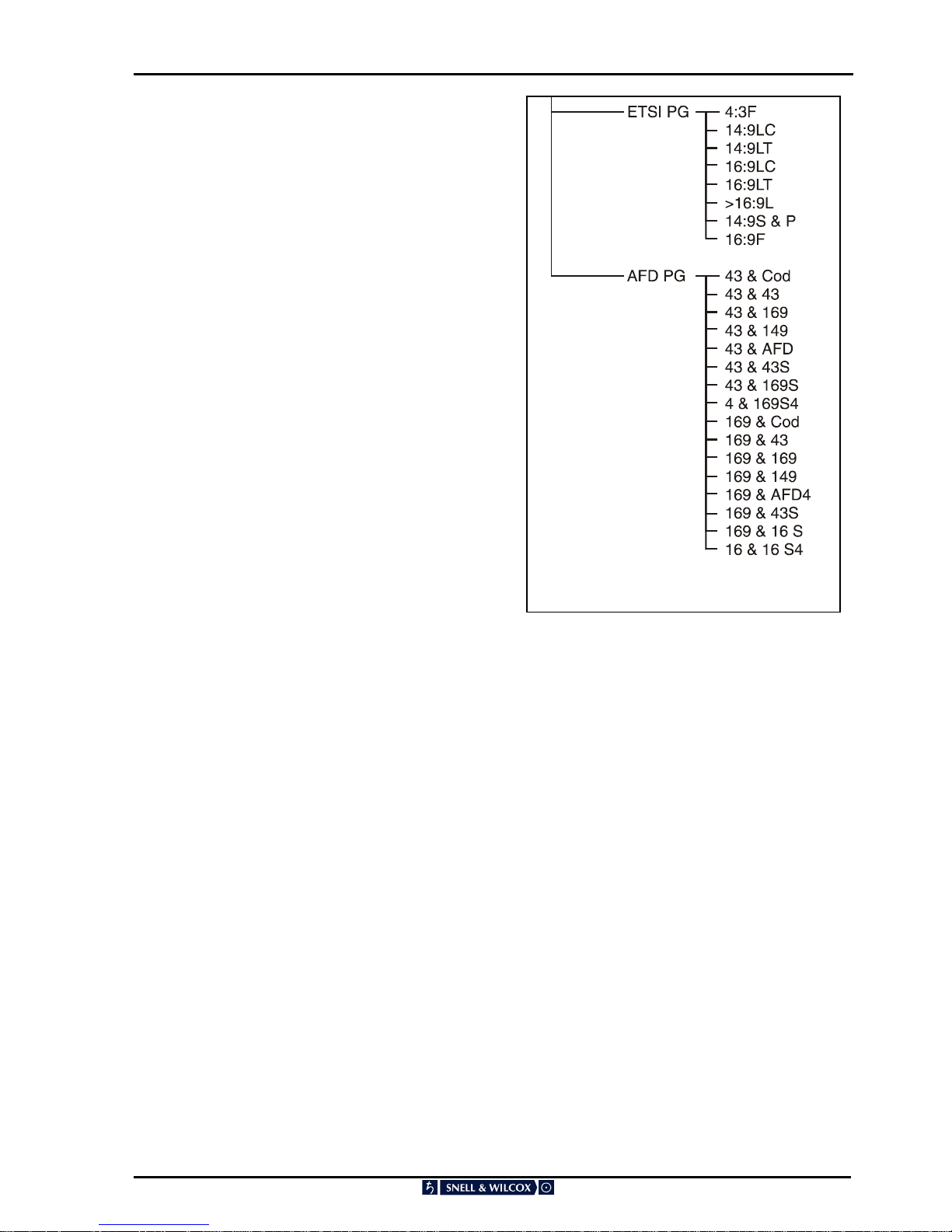
ETSI PG
This allows the user to program the ARC130S
action in when it receives the stated incoming line
23 (ETSI) signal.
Select ETSI PG and select from the list the line 23
signal that you want to activate the selected
display.
Select Line 23 4:3F
Select Line 23 14:9LC
Select Line 23 14:9LT
Select Line 23 16:9LC
Select Line 23 16:9LT
Select Line 23 >16:9L
Select Line 23 14:9S&P
Select Line 23 16:9 F
“LT” refers to Letterbox Top and “LC” refers to
Letterbox Centre, “S&P” refers to Shoot and
Protect and “F” refers to Full Frame.
When the particular line 23 signal is received, the
ARC130S will recall the display settings, produce
the appropriate output aspect ratio and set the line
23 output and video index signal.
AFD PG
This allows the user to program the ARC130S
action when it receives the stated incoming video
index or enhanced line 23 signal.
Selections available are:
4:3 & Cod
4:3 & 4:3
4:3 & 16:9
4:3 & 14:9
4:3 & AFD
4:3 & 4:3 S
4:3 & 16:9 S
4:3 & 16:9 S4
16:9 & Cod
16:9 & 4:3
16:9 & 16:9
16:9 & 14:9
16:9 & ARD4
16:9 & 4:3 S
16:9 & 16:9 S
16:9 & 16:9 S4
When the particular line 23 signal or video index is
received, the ARC 130S will recall the display
settings, produce the appropriate output aspect
ratio and set the line 23 output and video index
signal.
Note that if the incoming aspect ratio conversion
source is set to L23 AFD or L23 ETSI then it will
program the line 23 AFD memories.
If the Auto source is set to video index then it will
program the video index memories.

ARC130S SECTION 4
ARC130S 060801 Version 1 Issue 1 4.15
MEMORY
This allows you to store or recall display settings in
12 separate memories. From the Home Screen,
press ENT and scroll to Memory. Press ENT and
scroll between Store and Recall. Press ENT on the
selected function.
Store allows you to select the memory store you
wish to retain the current settings in. To store,
make sure that the display settings are the way you
want them to be, scroll to the store number you are
going to use and then press ENT. Keep a careful
record of the picture the settings are to be used
with.
Recall allows you to recall one of the user
memories. To recall, refer to your record of the
memory stores, scroll to the required user number
and then press ENT; the picture format will
immediately change according to the stored
parameters .
Note that the state of the Bypass button is also
kept in the user memories. If a user memory is
stored with Bypass turned ON, whenever that
memory is recalled Bypass will be activated.
This means that whenever a preset aspect ratio
conversion is selected, Bypass is turned OFF.
This feature allows users of the GPI to turn on the
Bypass mode via the GPI port.
See Appendix page 4.37 for a list of the
parameters stored in the memories.
Check allows the user to recall the Auto aspect
ratio memories without having to apply the relevant
auto widescreen signalling or GPI contact closure.
L23 ETSI – Selecting this presents the user with a
list of the eight possible incoming line 23 ETSI
codes. When one of these eight codes is selected
then, the auto memory corresponding to that line
23 code is recalled. Thus the ARC is put in the
same mode as it would have been if Auto line 23
ETSI input was selected and, that particular
widescreen signal was present on the input video.
L23 AFD – Selecting this presents the user with a
list of the sixteen possible incoming line 23 AFD
codes. When one of these sixteen codes is
selected then, the auto memory corresponding to
that line 23 code is recalled. Thus, the ARC is put
in the same mode as it would have been if Auto
line 23 AFD input was selected and, that particular
widescreen signal was present on the input video.
Memory
Sto
r
e
Store 1
Store 2
Store 3
Store 4
Store 5
Store 6
Store 7
Store 8
Store 9
Store 10
Store 11
Store 12
User 1
User 2
User 3
User 4
User 5
User 6
User 7
User 8
User 9
User10
User 11
User 12
Recall
Check
L23 ETSI
L23 AFD
Vid Ind
GPI Bin
Vid Ind– Selecting this presents the user with a list
of the sixteen possible incoming video index AFD
codes. When one of these sixteen codes is
selected then, the auto memory corresponding to
that video index code is recalled. Thus, the ARC is
put in the same mode as it would have been if Auto
video index input was selected and, that particular
widescreen signal was present on the input video.
GPI Bin– Selecting this presents the user with a list
of the sixteen possible incoming GPI Binary codes.
When one of these sixteen codes is selected then,
the auto memory corresponding to that GPI Binary
value is recalled. Thus, the ARC is put in the same
mode as it would have been if Auto GPI Binary
input was selected and, that particular Binary GPI
value was present on the GPI input.

ARC130S SECTION 4
ARC130S 060801 Version 1 Issue 1 4.16
SETUP
This allows you to select the ARC130S
configuration menu. From the Home Screen, press
ENT and scroll to Setup. Press ENT and scroll to
select the function you require. Then press ENT
again.
Bypass allows you to select whether the video is
interpolated or whether it is passed straight through
the unit (but with the normal unit delay). Each time
you press ENT, the message toggles between
NoBypass and Bypass; the default is NoBypass.
Clip allows you to turn the internal clipper on or off.
The clipper limits the 10-bit data to 940 for white
and 64 for black. Each time you press ENT, the
message toggles between Clip Off and Clip On.
Freeze allows you to turn the video freeze function
on and off. Each time you press ENT, the message
toggles between NoFreeze and Freeze.
Gamut Turns on or off the colour gamut checking
system. When On it ensures that the colour values
are legal.
Ip Loss controls the response to the loss of the
input video.
Black: the ARC130S output cuts to black when the
input is lost
Freeze: the ARC130S output freezes when the
input is lost
Ip Std allows you to select the incoming video
standard.
Auto: automatically detects the incoming video
standard.
625: forces the ARC130S input to the 625/50
standard.
525: forces the ARC130S input to the 525/59.94
standard
Ip Std
Ip Loss
Freeze
Black
Setup

ARC130S SECTION 4
ARC130S 060801 Version 1 Issue 1 4.17
Modes
Pair 1-2, Pair 2-1
This selects the way the input video fields are
paired before the application of the two-field pairing
mode filter (see above).
`If Pair 1-2 is selected then field 1’s are grouped
with the following field two.
If 2-1 is selected then field 2’s are grouped with the
following field 1’s.
Pair Off/On
Turning Pairing mode On causes the ARC to pair
up the incoming video fields into frames before
applying a two field vertical temporal aperture.
If a user has material that has all the programme
cuts on field 1’s, then selecting Pair As 1-2 (see
below) will ensure that the interpolation never
bleeds across programme cuts.
If the material has all cuts on field 2’s then
selecting Pair As 2-1 will ensure that there is no
interpolation across cuts.
Modes Film
Normal
Vid >2:2
2:2 Fil
2:2 2:2
Pair 1-2 / 2-1
Pair Off / On
Filter
Normal
Single

ARC130S SECTION 4
ARC130S 060801 Version 1 Issue 1 4.18
The Filter function allows two aperture filters to be
selected.
- Normal
- Single
Normal = uses the normal multi-field video
aperture
Single = uses a single field aperture.
The Normal aperture will produce better results
than the Single field aperture. However in some
special cases (e.g. programme material containing
DVE moves or scrolling captions) a single field
aperture may be preferred.
Process
Selects the filtering applied in the ARC130S .
V & H: This is the normal operating mode. Both
vertical and horizontal size and position control is
available.
H only: Horizontal processing only. Control of only
horizontal size and position is available. No vertical
or temporal filtering is applied.
V only: Vertical processing only. Control of only
vertical size and position is available. No horizontal
filtering is applied.
TPG Off allows you to turn on and off the internal
test pattern generator, the pattern being
determined by the TP Type selection. Each time
you press ENT, the message toggles between
TPG Off and TPG On.
TP Type allows you to select the test pattern that
will be produced when the internal TPG is switched
on. From the Home Screen, press ENT and scroll
to Setup. Press ENT and scroll to select TPG
Type. Then press ENT again.
Scroll to the pattern type you require and press
ENT. The patterns are digitally generated to exact
levels; to preserve their integrity there is no
adjustment.
Line 21 (525 only) allows you to select whether line
21 is a video line or a VITS line (usually closed
captioning). Each time you press ENT the
message toggles between L21 Vid and L21 Capt.
Process
V & H
H Only
V Only
Systime CoTimed/Early
f
Pair 1-2 / 2-1
Pair Off / On
Filter
Normal
Single

ARC130S SECTION 4
ARC130S 060801 Version 1 Issue 1 4.19
Systime
In order to improve the system timing a new mode
has been introduced. This mode ensures that
output line 23 and video index signalling occurs on
the same field that the video transition occurs. It
also ensures that GPI contact closures that are
co-timed with the video, that they wish to change,
are properly timed. In earlier releases the GPI
closure had to be done in advance of the desired
transition.
This new timing model is selected by default with
version A14 and later software. Existing users of
the ARC who wish to upgrade to this version of
software but have an existing remote control
system in place may select the old timing model if
they desire. This ensures compatibility between the
new ARC software and the users existing
infrastructure.
Selections are CoTimed (for new model) or Early
(for old model)
This function may also be entered via RollCall.
The Trans menu controls the type of transition
between display sizes that the ARC performs.
Trans – Period
This sets the time that the ARC takes to move
between one picture size and the next when the
ARC is in Slew mode (see below). If Update is set
to F1 and F2 (see Setup- Update menu below)
then the time is in video fields otherwise it is in
Frames. The default period is one field
Trans -- Type
This sets the type of transition that the ARC will
perform.
Trans -- Type -- Slew
In Slew mode the ARC moves gradually from one
picture size to the next taking the time set on the
Trans – Period menu and following the profile set
on the Trans – Profile menu.
Instant
In instant mode the ARC cuts directly from one
picture size to the next. Note that Instant mode is
the same as Slew mode with the duration set to
one field.
Systime CoTimed/Early
Type
Slew
Instant
Trigger
Profile
Linear
Accel
Decel
S-Curve
Update
Trans
Period
Trigger
In Trigger mode, the ARC will slew from one
picture size to the next using the duration and
profile set on the Trans menus. However, the
transition will not be started until a trigger
command is sent on the RS-422 remote control
channel. This is useful when remote controlling the
ARC as the display parameters can be sent in
advance of the transition and, only the trigger
command needs to be sent in real time.
Warning, if the ARC is put in Trigger mode then it
will not react to front panel commands which affect
the picture display parameters (size, aspect, pan
and Pos).
Trans -- Profile
This sets the shape of the transition that the ARC
will perform.
Trans -- Profile -- Linear
In Linear mode the ARC moves linearly from one
picture size to the next.
Accel
In accelerate mode the ARC starts the transition
with a low rate of picture size change from field to
field and gradually increases the rate of change.
Decel
In decelerate mode the ARC starts the transition
with a high rate of picture size change from field to
field and gradually decreases the rate of change.
S-Curve
In S-Curve mode the ARC starts the transition
slowly, then increases the rate of change then
reduces the rate of change at the end of the
transition.

ARC130S SECTION 4
ARC130S 060801 Version 1 Issue 1 4.20
Update
This allows you to select whether a change in
output display parameters occurs at field or frame
rate. This is significant if line 23 signalling is used
(this signal is only present once per frame). If the
ARC130S is in the Auto mode and line 23
signalling is set to Auto output, when a change in
aspect ratio is signalled at the input, it is preferable
that the output video change and the output line
signalling occur together. This may not be the case
due to internal vertical genlock timing or timing of
the external reference. To ensure that the video
change and output signalling occur together it is
recommended that Update is set to “Field 1” when
in the Auto mode.
If “F1 & F2” is selected, the video at the output will
change at the first available field boundary after a
button has been pressed or a remote control
command has been received.
If “F1 only” or “F2 only” is selected the video at the
output will only change at the start of the
appropriate output field type after a button has
been pressed or a remote control command has
been received.
RC Add
When this item is selected the ARC displays the
RollCall address of the unit in Hexadecimal. Note
that the address cannot be changed using this
menu entry, it can only be changed using the rotary
switches as described in Section 3.
Log On – selecting this menu item toggles
between Log On and Log Off. This item turns On
and Off the RollCall Log server function in RollCall
network applications.
Update
RC Add
Log On/Log Off
RS 422
Baud
422 Bit
38400
9600
4800
7 Bit
8 Bit
Proto
Normal
Alt
RS422
This allows the RS422 communications function to
be set up.
Baud controls the Baud rate used on the RS422
remote control channel.
The rate may be set to any of the following:
38400
9600
4800
Note that if the ARC is to be controlled by a Snell &
Wilcox ARC remote control unit then the Baud rate
must be set to 38400 Baud.
422 Bit – this sets the number of data Bits used on
the RS-422 remote control link when the Normal
remote control protocol is in use (see below).
Note that if the ARC is to be controlled by a Snell
and Wilcox ARC remote control unit then this must
be set to 7 Bits.
Proto – this selects the remote control protocol in
use on the RS 422 remote control link. Normal is
the default protocol and this provides control of all
parameters of the ARC.
If Alt is selected an alternate protocol is active.
This is for use with Philips automation systems that
are unable to support the rich feature set of the
ARC.
This protocol only provides a limited number of
commands and is described in more detail on page
4.53.
The full Snell and Wilcox protocol is widely used
and is freely available from Snell and Wilcox.

ARC130S SECTION 4
ARC130S 060801 Version 1 Issue 1 4.21
VITS
This allows you to control the blanking of the
vertical interval lines. Note that for 625/50
operation the lines are 7-22 and 320-335, and for
525/59.94 operation the lines are 10-20 (and line
21 if set up to L21 Capt, as above) and 272-282.
From the Home Screen, press ENT and scroll to
VITS. Press ENT and scroll to select the function
you require. Then press ENT again.
PassAll passes all the VITS lines through the
ARC130S untouched. When selected and ENT is
pressed, the message “Done” appears.
BlankAll blanks all the VITS lines. When selected
and ENT is pressed, the message “Done” appears.
Field 1 allows you to selectively pass/blank field 1
vertical interval lines. Similarly, Field 2 allows you
to selectively pass/blank field 2 vertical interval
lines.
Setline: selects which vertical interval lines of the
appropriate field are to be blanked/passed.
State: turns on and off the blanking for the lines set
in Setline. Pressing ENT toggles the message
between “Pass” and “Blanked”.

ARC130S SECTION 4
ARC130S 060801 Version 1 Issue 1 4.22
Abbreviated Explanation of Aspect Ratio Technical Codes for Video and Picture Sources
(For full details see Section 6)
These codes can used to describe the aspect ratios used when graphics or video sources are composed or
generated. They describe the image and the raster ratios.
Code Specification:
Code format is thus: AABCCD
Where AA is the first parameter, B is the second
etc.
The four parameters of the code must used in the
order specified. Not all parameters have to be
used if not appropriate or known, however B (The
Display Format) should be present to prevent
ambiguity.
AA Active Image Aspect Ratio - Number(s)
Aspect Ratio of Active Image Area expressed as a
two digit abbreviated numeric value where the
comparison ratio is against a height of 9. Active
Image area is the part of the raster / bitmap that
contains picture information. 12 is normally used
for 4 by 3 (12 by 9).
ie. Two digit number giving the aspect ratio of the
picture area that viewers are interested in, that is
neglecting any areas of continuous and static black
due to letter-boxing or pillar-boxing. Numbers
describing ratios seen in use at present are: 12,
14, 15 (Super 16), 16, 17 (1.85:1), 21 (2.35:1), 24.
Thus 14 : 9 becomes 14.
B Display Format - Letter
The visual effect of the image and display raster
aspect ratios combined. Abbreviated as an initial.
P for pillar-box. That is full height but with
black down the sides.
L for letter-box. That is full width with
black top and bottom.
F for full frame. Display and Image aspect
ratios are the same.
i.e. if it’s purely in letter box presentation put in an
L etc. e.g. 14L12A - ”14 by 9 letterbox for..”. This
letter confirms what the pictures look like and
separates the two ratio numbers.
Note: Letter A has been proposed for material
converted an Anamorphic presentation - that is the
image is designed to be displayed distorted. This
can be as a result of stretching a picture to fit a
given display shape whilst avoiding cropping.
Active Image
Area

ARC130S SECTION 4
ARC130S 060801 Version 1 Issue 1 4.23
CC Raster aspect ratio - Number(s)
Aspect Ratio of the full raster when correctly
displayed expressed as a two digit abbreviated
numeric value where the comparison ratio is
against a height of 9. 12 is used for 4 by 3 (12 by
9)
i.e. Two digit number(s) giving the aspect ratio of
entire picture / raster / graphics bitmap, including
all the black of any Letterbox or Pillarbox area, that
gives a correctly displayed image.
Numbers describing ratios seen in use at present
are 12, 14, 15 (Super16), 16, 17 (1.85:1), 21
(2.35:1Cinemascope), 24.
e.g. A 16 : 9 full height “anamorphic” raster is
shown as 16.
A request for material suitable for 16 by 9 TX could
just be “supply it in F16 format”.
Examples of common aspect ratios expressed as
two digit numbers using this notation.
Aspect Ratio Two Digit Number
4:3 12
14:9 14
15:9 15
16:9 16
1.85:1 17
Generally:
If the aspect ratio is expressed as: -
A : B (width to height)
Then the two digit number N representing the
comparison ratio against a height of 9 will be given
by
N
9
B
xA=
or by transposing
B=
9
N
xA
and
A
B
9
xN=
Full Raster
Area

ARC130S SECTION 4
ARC130S 060801 Version 1 Issue 1 4.24
PRESET ASPECT RATIO SELECTIONS
Front panel
Designation
BBC Notation Full Description
Aspect
Value
Size Value
1.77F>FH 16F16 > 12F12 16:9 picture to full height 4:3 picture for
presentation on a 4:3 screen (left hand and
right hand edges of original 16:9 image are
cropped
1.333 1.000
Input Picture Output Picture
Front panel
Designation
BBC Notation Full Description
Aspect
Value
Size Value
1.85L>FH 1.85:1 Letterbox picture to full height 4:3
picture with left hand and right hand edges of
original 1.85:1 image cropped
1.000 1.388
Input Picture
Output Picture
ARC130S SECTION 4
ARC130S 060801 Version 1 Issue 1 4.25
Front panel
Designation
BBC Notation Full Description
Aspect
Value
Size Value
1.66L>FH 15L12 > 12F12 15:9 letterbox picture to full height 4:3 picture
with left hand and right hand edges of original
15:9 image cropped
1.000 1.250
Input Picture Output Picture
Front panel
Designation
BBC Notation Full Description
Aspect
Value
Size Value
1.55L>FH 14L12 > 12F12 14:9 letterbox picture to full height 4:3 picture
with left hand and right hand edges of original
14:9 image cropped
1.000 1.167
Input Picture Output Picture

ARC130S SECTION 4
ARC130S 060801 Version 1 Issue 1 4.26
Front panel
Designation
BBC Notation Full Description
Aspect
Value
Size Value
1.77F>LB 16F16 > 16L12 16:9 Anamorphic picture converted to 16:9
letterbox picture for presentation on 4:3 screen
(black bars above and below image)
1.333 0.750
Input Picture Output Picture
Front panel
Designation
BBC Notation Full Description
Aspect
Value
Size Value
1.85F>LB 1.85:1 Anamorphic picture converted to 1.85:1
letterbox picture for presentation on 4:3 screen
(black bars above and below image)
1.388 0.721
Input Picture Output Picture

ARC130S SECTION 4
ARC130S 060801 Version 1 Issue 1 4.27
Front panel
Designation
BBC Notation Full Description
Aspect
Value
Size Value
1.66F>LB 15F15 > 15L12 15:9 Anamorphic picture converted to 15:9
letterbox picture for presentation on 4:3 screen
(black bars above and below image)
1.250 0.800
Input Picture Output Picture
Front panel
Designation
BBC Notation Full Description
Aspect
Value
Size Value
1.77F>1.55L 16F16 > 14L12 16:9 Anamorphic picture converted to 14:9
letterbox picture for presentation on a 4:3
screen (black bars above and below image and
right hand and left hand edges of picture
slightly cropped)
1.333 0.857
Input Picture Output Picture

ARC130S SECTION 4
ARC130S 060801 Version 1 Issue 1 4.28
Front panel
Designation
BBC Notation Full Description
Aspect
Value
Size Value
4:3>Cur 12F12 > 12P16 4:3 image converted to 4:3 pillarbox/curtains
image in 16:9 anamorphic. (4:3 horizontally
squeezed image with black bars to left and
right of output)
0.750 1.000
Input Picture Output Picture
Front panel
Designation
BBC Notation Full Description
Aspect
Value
Size Value
1.55>Cur 14L12 > 14P16 14:9 letterbox picture in 4:3 converted to 14:9
pillar-box/curtains image in 16:9 anamorphic
(14:9 horizontally squeezed image with 1:9
black bars to left and right of output)
0.750 1.167
Input Picture Output Picture

ARC130S SECTION 4
ARC130S 060801 Version 1 Issue 1 4.29
Front panel
Designation
BBC Notation Full Description
Aspect
Value
Size Value
4:3>FW 4:3 image anamorphically squeezed and
scaled up to fill full 16:9 width. Top and bottom
of original 4:3 image cropped at output
0.750 1.333
Input Picture Output Picture
Front panel
Designation
BBC Notation Full Description
Aspect
Value
Size Value
1.77L>1.77F 16L12 > 16F16 16:9 letterbox in 4:3 converted to 16:9
anamorphic full height image
0.750 1.333
Input Picture Output Picture

ARC130S SECTION 4
ARC130S 060801 Version 1 Issue 1 4.30
APPENDIX – Video Index and Enhanced Line 23
The ARC130S can read incoming video index signals and output it’s own video index signal. Video index is a
signal embedded in the D1 output stream that can be used to convey aspect ratio information. The basic
version of video index is described in SMPTE document RP186. An enhanced version of video index
incorporating more aspect ratio information has been introduced in the United Kingdom for control of MPEG
encoders. The ARC130S supports both forms of video index and, they are referred to as SMPTE186 and AFD
Spec’ version throughout. (AFD is Active Format Descriptor). The serial data format of the video index is
described in SMPTE document SMPTE125M-1995.
In the United Kingdom, a modified version of line 23 signalling which allows the embedding of the same
information as that in AFD spec Video Index signals has been defined. The ARC130S supports this AFD spec
version of line 23 at both it’s input and output. The new line 23 will be referred to as L23 AFD and the previous
version of line 23 as L23 ETSI throughout.
BACKGROUND INFORMATION ON VIDEO INDEX
The original SMPTE RP186 video index scheme includes in the very first data byte (Class 1.1 data Octet 1) a
scanning system field. This can signal either 4:3 or 16:9 using the bottom 3 bits of the data byte as shown
below.
Octet Value Meaning B2 B1 B0
0 no information 0 0 0
1 525/59.94 4:3 0 0 1
2 625/50 4:3 0 1 0
3 Reserved 0 1 1
4 Reserved 1 0 0
5 525/59.94 16:9 1 0 1
6 625/50 16:9 1 1 0
7-255 Reserved 1 1 1
Within Europe an extension to this data byte has been defined and is known as the ARDSPEC version. AFD
being Active Format Descriptor. This retains the meaning of the bottom 3 bits of the data byte as 4:3 or 16:9
but in addition, it defines the meanings of the next 3 bits as follows.
Active format Intended aspect ratio of active region B5 B4 B3
0 Active region is same as coded frame000
1 4:3 001
2 16:9 0 1 0
3 14:9 0 1 1
4 Reserved for future use 1 0 0
5 4:3 with shoot-and-protect 14:9 centre 1 0 1
6 16:9 with shoot-and-protect 14:9 centre 1 1 0
7 16:9 with shoot-and-protect 4:3 centre 1 1 1
The enhanced version of Line 23 (L23 AFD) basically embeds the sane information in the line 23 data. i.e. the
Scanning system and AFD fields. In addition, it provides four User bits.

ARC130S SECTION 4
ARC130S 060801 Version 1 Issue 1 4.31
The ARC130S can read incoming aspect ratio signalling and output it. This means that the aspect ratio
conversion it performs can be automatically controlled by the incoming video signalling. It is possible to
program the action that the ARC takes for each of the incoming signalling values. The parameters that are
stored when the signalling is programmed are as follows:
1. Output picture Size.
2. Output picture Aspect ratio.
3. Output picture Horizontal position.
4. Output picture Vertical position.
5. Output line 23 signal.
6. Output video index signal.
7. Bypass Mode setting.
These parameters are also stored for the User Display Memories and are recalled when a User Memory
is selected.
Both line 23 and video index outputs can be turned on simultaneously. Note that if the line 23 output mode is
set to AFD then the line 23 output data will be the same as that being output on the video index signal. It is
however possible to program the Line 23 AFD and Video Index inputs independently.
The video index information is inserted on line 11 and 324 for 625 line systems and lines 14 and 277 for 525
line systems.

ARC130S SECTION 4
ARC130S 060801 Version 1 Issue 1 4.32
PROTOCOL
The ARC130S software supports a second RS 422 remote control protocol. This has been done so that the
ARC can be controlled by Philips automation systems that are unable to support the full command set of the
Snell & Wilcox ARC’s.
If the alternate protocol is selected the RS 422 link is automatically switched to eight data bits, one stop bit and
no parity. The baud rate is selectable from the ARC menus and may be set to 38400, 9600 or 4800 baud. Note
that the RS 422 data bits menu item only controls the number of RS 422 data bits in use when the default Snell
& Wilcox protocol is in use.
The protocol accepts messages of the form: -
<stx><address><command><etx>
Where: -
<stx> = One byte with hexadecimal value 0x02. This indicates the start of a message packet.
<address> = One byte representing the ARC address. The MSB is always set to one. This byte can take a
value in the range 0x81 to 0xE3 representing addresses one to ninety-nine (decimal). The
ARC checks that the value is in this range and will respond to any valid address. Commands
with an address outside the valid range are ignored.
<command>= One byte which represents the desired command. The MSB is always one. See table below of
valid command numbers.
<etx> = One byte with hexadecimal value 0x03. This indicates the end of a message packet.
The accepted commands are either a Poll command or a Recall preset command.
If a Poll command is received then the ARC will respond with an <
ACK> byte (0x04) if the ARC is available to
receive messages. If a communications error occurs, a <
NAK> byte (0x05) will be sent by the ARC.
If a Recall Preset command is received, the ARC will respond with an <
ACK> byte (0x04) if the message is
received and the Preset is updated. If a communications error occurs, a <
NAK> byte (0x05) will be sent by the
ARC and the Preset will not be updated.
Command Byte Command Name ARC Action
0x80 Poll
0x90 Recall Preset 1 Recall User Memory 1
0x91 Recall Preset 2 Recall User Memory 2
0x92 Recall Preset 3 Recall User Memory 3
0x93 Recall Preset 4 Recall User Memory 4
0x94 Recall Preset 5 Recall User Memory 5
0x95 Recall Preset 6 Recall User Memory 6
0x96 Recall Preset 7 Recall User Memory 7
0x97 Recall Preset 8 Recall User Memory 8
0x98 Recall Preset 9 Recall User Memory 9
0x99 Recall Preset 10 Recall User Memory 10
0x9A Recall Preset 11 Recall User Memory 11
0x9B Recall Preset 12 Recall User Memory 12
0x9C Recall Preset 13 Recall Auto Mode
Table - RS 422 Command Numbers

ARC130S SECTION 4
ARC130S 060801 Version 1 Issue 1 4.33

ARC130S SECTION 4
ARC130S 060801 Version 1 Issue 1 4.34
THE ROLLCALL MENU SYSTEM
(See `ARC130S Menu System' drawing on
previous page)
All operational parameters and selections are
made using a system of menus displayed in two
LCD windows.
Menus are selected by push buttons and further
menu selections made by rotating a spinwheel and
pressing a push button.
The spinwheel also allows continuously variable
parameters, e.g. Gain, to be adjusted and the
setting to be seen in the LCD window.
Various specific operations may be achieved by
operating dedicated push buttons.
The system may be considered structured as a set
of menus and sub-menus that are displayed in the
central LCD window. The left hand LCD window
will display the current input/output standard
selections of the unit and information messages.
The DISPLAY buttons allows the information
displayed to toggle between the modules current
setup and more detailed data including software
version etc.
The highest level menu is called the Main Menu
and contains the names of the lower-level menus
that may be scrolled through using the spinwheel.
The sub-menu may be then be selected by
pressing the push button adjacent to the
arrowhead in the text line of the menu name.
This sub-menu will then be displayed in the window
and will have the option of selecting another submenu in the same manner, or allow the adjustment
of a particular parameter. Parameters enabled will
appear as highlighted reverse text (white text on a
black background)
Note that the spinwheel will be operative when the
LED labelled SCROLL is illuminated, indicating that
a menu with more than four text lines is being
displayed. Operating the spinwheel then allows the
other text lines to be displayed.

ARC130S SECTION 5
System Overview
ARC130S 060801 Version 1 Issue 1 5.1
The ARC130S is a digital-in digital-out Aspect ratio
Converter.
To change the aspect ratio, the picture has to be
stretched or compressed in either or both the
horizontal and vertical plane. To stretch or
compress the picture, data has to be interpolated
from adjacent pixels.
The ARC130S vertical temporal interpolation
operates on four fields and six lines of the
incoming video and is effectively a 24-point filter
(optimised individually for every pixel point of the
picture). Filtering is carried out separately for
luminance and chrominance. A large horizontal
filter is applied after the vertical filter.
There are two factors influencing the performance
of the interpolation, one is the number of points
being used in the filter, and the other is the need to
carry out vertical-temporal interpolation. To explain
the latter factor, six lines on one field would only
access half the information in the interlace system
but when we use 12 lines from a full frame, the
information in the second field is displaced in time
from the first field; this must be taken into account
when interpolating.
In the diagram you are looking at the lines of the
video structure end-on as if you are looking into the
side of the CRT face while the pixels of four fields
are displayed. The field offset of the required pixel
from field 2 is the temporal offset and the line
offset from the nearest line in field 2 is the vertical
offset. The area shaded is the aperture which is
centred on the required pixel position. A proportion
of every pixel in the aperture is used in creating the
new pixel; the proportions diminish as the distance
from the required pixel increases.
In addition to changing the picture aspect ratio, the
unit can read and act on line 23 signalling on the
input signal and can insert line 23 signalling on the
output.

ARC130S SECTION 5
System Overview
ARC130S 060801 Version 1 Issue 1 5.2
BLOCK DIAGRAM DESCRIPTION
Referring to the block diagram (drawing ARC130S
), the OPI card decodes the D1 serial digital video
into separate luminance and chrominance data
streams and feeds them to FIFO buffers, which
allow for different input and output clock rates.
The data is then fed to the INT (Interpolator) card
where all the required vertical/temporal and
horizontal interpolation is carried out.
From the INT card the data is fed back to the OPI
card where it is applied to a gamut limiting circuit.
When gamut limiting is selected, any digital values
that would provide illegal video values are brought
within bounds.
From the gamut system, the data is output blanked
and converted back to serial digital (656) format
before being fed out of the unit.
Data from line 23 (625-line systems) is decoded
and, when Auto is selected, provides automatic
selection of the aspect ratio via the control circuits.
If the GPI interface option is fitted, an input on one
of the four lines can be used to select a memorised
output format and automatically set the output
aspect ratio.
The syncs and timing are obtained from the video
input, via a phase-locked-loop.
An internal pattern generator can be connected to
the output in place of the interpolated signal.
The control circuit on the OPI card accepts inputs
from the front panel, the card edge switches, or a
remote panel (as well as the GPI and line 23
inputs) and provides the necessary control signals
to the rest of the ARC 130S. It also provides an
output which is equal to the delay through the unit.

ARC130S SECTION 6
ARC130S 060801 Version 1 Issue 1 6.1
Aspect Ratio Technical Codes for Video and
Picture Sources
Proposal Version 3.1 - see end of document for changes from previous versions 2.1 &3.0
These codes can used to describe the aspect ratios used when graphics or video sources are composed or
generated. They describe the image, the raster and conversion protection ratios. They are designed to be
compact yet easy to decode (readable), and are for use in materials requests, recording reports and labelling
including VTR Clocks. They can also be used verbally to overcome some of the terminology confusions that
exist at present.
Code Specification:
Code format is thus: AABCCD Where AA is the first parameter, B is the second etc.
The four parameters of the code must used in the order specified. Not all parameters have to be used if not
appropriate or known, however B ( The Display Format ) should be present to prevent ambiguity.
AA Active Image Aspect Ratio - Number(s)
Aspect Ratio of Active Image Area expressed as a two digit abbreviated numeric value where the
comparison ratio is against a height of 9. Active Image area is the part of the raster / bitmap that
contains picture information. 12 is normally used for 4 by 3 ( 12 by 9 ). Note that areas involved with
code entry into database systems ask that only two digit codes are to be used. Code 99 is used where
ratio is very non-standard and is separately documented.
ie. Two digit number giving the aspect ratio of the picture area that viewers are interested in, that is
neglecting any areas of continuous and static black due to letter-boxing or pillar-boxing. Numbers
describing ratios seen in use at present are: 12, 14, 15 ( Super 16 ), 16, 17 (1.85:1), 21 (2.35:1), 24.
Thus 14 : 9 becomes 14.
B Display Format - Letter
The visual effect of the image and display raster aspect ratios combined. Abbreviated as an initial.
P for pillar-box. That is full height but with black down the sides.
L for letter-box. That is full width with black top and bottom.
F for full frame. Display and Image aspect ratios are the same.
M for mixed, that is variations within the material of P, L or F
ie. if it’s purely in letter box presentation put in an L etc. e.g. 14L12A - ”14 by 9 letterbox for..”. This
letter confirms what the pictures look like and separates the two ratio numbers.
Note: Letter A has been proposed for material converted an Anamorphic presentation - that is the
image is designed to be displayed distorted. This can be as a result of stretching a picture to fit a
given display shape whilst avoiding cropping.

ARC130S SECTION 6
ARC130S 060801 Version 1 Issue 1 6.2
CC Raster aspect ratio - Number(s)
Aspect Ratio of the full raster when correctly displayed expressed as a two digit abbreviated numeric
value where the comparison ratio is against a height of 9. 12 is used for 4 by 3 ( 12 by 9 ) Note that
areas involved with code entry into database systems ask that only two digit codes are to be used.
Code 99 is used where ratio is very non-standard and is separately documented.
ie. Two digit number(s) giving the aspect ratio of entire picture / raster / graphics bitmap, including all
the black of any Letterbox or Pillarbox area, that gives a correctly displayed image - . Numbers
describing ratios seen in use at present are: 12, 14, 15 ( Super16 ), 16, 17 ( 1.85:1), 21 (2.35:1
Cinemascope), 24.
e.g. A 16 : 9 full height “anamorphic” raster is shown as 16.
A request for material suitable for 16 by 9 TX could just be “supply it in F16 format”.
D Protection for Conversion. - Letter
This parameter is for material prepared with “Shoot Protection” for subsequent conversion into other
image formats that may safely crop the image. The letter code describes which format the material is
“Shoot Protected” for. This parameter’s primary use is for transmission with live conversion to indicate
on play-out which conversion ratios are required or possible. These letter codes can be applied to both
Letterbox and Pillarbox format conversions. Such letter codes are already in use by BBC Presentation.
A 16 : 9 protection . ( “Use All of 16:9 image”. Deep letterbox in 4:3. )
B protection for conversion to 14 : 9.
C protection for 4 : 3. ( 4 : 3 Centre cut-out format when from 16:9 full frame.)
D protection for 15 : 9
N or (blank). No extra protection other than that for the current display format.
There may be additional uses for this parameter and further letter codes may be
specified.
Examples:
16F16B16 : 9 image for 16 : 9 display Shoot Protected for conversion to 14 : 9.
A full frame 16:9 TX tape protected for cropping and conversion to a 14:9 format such as 14: 9
letterbox in 4 :3 raster - 14L12.
16F16C16 : 9 image for 16 : 9 display Shoot Protected for conversion to 12 : 9.
A full frame 16:9 TX tape Centre Cut-out protected for cropping and conversion to a 4:3 format
such as 12L12 the standard 4:3 PAL format - 12L12.
12F12N (12:9) 4:3 standard aspect ratio full height pictures. Standard PAL.
14L12N12F12N
16F16B
16F16C

ARC130S SECTION 6
ARC130S 060801 Version 1 Issue 1 6.3
14L12N 14: 9 letterbox for 12:9 (4:3) display.
The standard letter-boxed conversion to 4:3 format for Widescreen originated programs.
21L16 21:9 letterbox made for 16:9 display.
Full 21:9 Cinemascope image as a letterbox in 16: 9 Widescreen TX format. No extra
protection specified.
14P16B 14:9 pillar-boxed image for 16:9 display. 14:9 protected.
14:9 Pillarbox within a 16:9 display raster. Typically this would be 4:3 archive material
converted to Widescreen such that when reconverted on play-out to 14:9 Letterbox (14L12)
for 12:9 (4:3) PAL TX, only the black edges are lost.
15F15B 15:9 full raster images shot protecting a 14:9 area.
These originate from graded telecine transfers of the entire Super 16 film frame where
conversion to more than one final format is required.
21F21 21:9 full raster images.
These are normally graded telecine transfers from the entire Cinemascope film frame where
conversion to more than one final format is required. Pictures with “Very tall thin people”.
Changes from ver. 2.1: 4 or 04 removed as an option for 4:3. Addition of aspect code 99.
Addition of display format type A Addition of extra examples and figures.
Changes from ver. 3.0: Addition of protection code D
End of document
Source of Document:
Aspect Ratio Technical Codes for Video and Picture Sources. Proposal 3.1
Bill Bulford BBC PP&GD R&D 7/09/98 wcode31.doc
21L16
21F21
14P16B
15F15B

ARC130S SECTION 6
ARC130S 060801 Version 1 Issue 1 6.4
Abbreviated Explanation of Aspect Ratio Technical Codes for Video and Picture Sources
(For full details see Section x, Appendix 2)
These codes can used to describe the aspect ratios used when graphics or video sources are composed or
generated. They describe the image and the raster ratios.
Code Specification:
Code format is thus: AABCCD
Where AA is the first parameter, B is the second
etc.
The four parameters of the code must used in the
order specified. Not all parameters have to be
used if not appropriate or known, however B (The
Display Format) should be present to prevent
ambiguity.
AA Active Image Aspect Ratio - Number(s)
Aspect Ratio of Active Image Area expressed as a
two digit abbreviated numeric value where the
comparison ratio is against a height of 9. Active
Image area is the part of the raster / bitmap that
contains picture information. 12 is normally used
for 4 by 3 (12 by 9).
ie. Two digit number giving the aspect ratio of the
picture area that viewers are interested in, that is
neglecting any areas of continuous and static black
due to letter-boxing or pillar-boxing. Numbers
describing ratios seen in use at present are: 12,
14, 15 (Super 16), 16, 17 (1.85:1), 21 (2.35:1), 24.
Thus 14 : 9 becomes 14.
B Display Format - Letter
The visual effect of the image and display raster
aspect ratios combined. Abbreviated as an initial.
P for pillar-box. That is full height but with
black down the sides.
L for letter-box. That is full width with
black top and bottom.
F for full frame. Display and Image aspect
ratios are the same.
i.e. if it’s purely in letter box presentation put in an
L etc. e.g. 14L12A - ”14 by 9 letterbox for..”. This
letter confirms what the pictures look like and
separates the two ratio numbers.
Note: Letter A has been proposed for material
converted an Anamorphic presentation - that is the
image is designed to be displayed distorted. This
can be as a result of stretching a picture to fit a
given display shape whilst avoiding cropping.
Active Image
Area

ARC130S SECTION 6
ARC130S 060801 Version 1 Issue 1 6.5
CC Raster aspect ratio - Number(s)
Aspect Ratio of the full raster when correctly
displayed expressed as a two digit abbreviated
numeric value where the comparison ratio is
against a height of 9. 12 is used for 4 by 3 (12 by
9)
i.e. Two digit number(s) giving the aspect ratio of
entire picture / raster / graphics bitmap, including
all the black of any Letterbox or Pillarbox area, that
gives a correctly displayed image.
Numbers describing ratios seen in use at present
are 12, 14, 15 (Super16), 16, 17 (1.85:1), 21
(2.35:1Cinemascope), 24.
e.g. A 16 : 9 full height “anamorphic” raster is
shown as 16.
A request for material suitable for 16 by 9 TX could
just be “supply it in F16 format”.
Examples of common aspect ratios expressed as
two digit numbers using this notation.
Aspect Ratio Two Digit Number
4:3 12
14:9 14
15:9 15
16:9 16
1.85:1 17
Generally:
If the aspect ratio is expressed as: -
A : B (width to height)
Then the two digit number N representing the
comparison ratio against a height of 9 will be given
by
N
9
B
xA=
or by transposing
B=
9
N
xA
and
A
B
9
xN=
Full Raster
Area
 Loading...