

Page 1

www.s-a-m.com
Installation & Quick Start Manual
Sirius 840 Router
A 576 x 576 non-expandable frame, with up to
140 multiviewer outputs in a 27U chassis
Page 2

Sirius 840 Installation Manual www.s-a-m.com
Issue 2 Rev 3 Page 2 © 2016 SAM
Page 3

Sirius 840 Installation Manual www.s-a-m.com Contents
Issue 2 Rev 3 Page 3 © 2016 SAM
Contents
1. About this Manual . . . . . . . . . . . . . . . . . . . . . . . . . . . . . . . . . . . . . . . . . . . . . . . . . . . 5
1.1 Contact Details . . . . . . . . . . . . . . . . . . . . . . . . . . . . . . . . . . . . . . . . . . . . . . . . . . . 5
1.2 Copyright and Disclaimer . . . . . . . . . . . . . . . . . . . . . . . . . . . . . . . . . . . . . . . . . . . 5
2. Warnings and Precautions . . . . . . . . . . . . . . . . . . . . . . . . . . . . . . . . . . . . . . . . . . . . 7
2.1 Explanation of Safety Symbols . . . . . . . . . . . . . . . . . . . . . . . . . . . . . . . . . . . . . . . 9
2.2 Safety Warnings . . . . . . . . . . . . . . . . . . . . . . . . . . . . . . . . . . . . . . . . . . . . . . . . . . 9
2.3 Lithium Batteries . . . . . . . . . . . . . . . . . . . . . . . . . . . . . . . . . . . . . . . . . . . . . . . . . . 9
2.4 Fiber Output Modules Warning . . . . . . . . . . . . . . . . . . . . . . . . . . . . . . . . . . . . . . 10
2.5 Cable Management. . . . . . . . . . . . . . . . . . . . . . . . . . . . . . . . . . . . . . . . . . . . . . . 10
2.6 Power Supplies . . . . . . . . . . . . . . . . . . . . . . . . . . . . . . . . . . . . . . . . . . . . . . . . . . 10
2.7 Earth Cables . . . . . . . . . . . . . . . . . . . . . . . . . . . . . . . . . . . . . . . . . . . . . . . . . . . . .11
2.7.1 Important Protective Earth Information . . . . . . . . . . . . . . . . . . . . . . . . . .11
2.7.2 Important Functional Earth Information . . . . . . . . . . . . . . . . . . . . . . . . . .11
2.8 Safety Standards. . . . . . . . . . . . . . . . . . . . . . . . . . . . . . . . . . . . . . . . . . . . . . . . . 12
3. Prerequisites. . . . . . . . . . . . . . . . . . . . . . . . . . . . . . . . . . . . . . . . . . . . . . . . . . . . . . . 13
3.1 Size Requirements . . . . . . . . . . . . . . . . . . . . . . . . . . . . . . . . . . . . . . . . . . . . . . . 13
3.1.1 Sirius 840 Dimensions . . . . . . . . . . . . . . . . . . . . . . . . . . . . . . . . . . . . . . 13
3.1.2 Power Supply Shelf . . . . . . . . . . . . . . . . . . . . . . . . . . . . . . . . . . . . . . . . 14
3.2 Weights . . . . . . . . . . . . . . . . . . . . . . . . . . . . . . . . . . . . . . . . . . . . . . . . . . . . . . . . 15
3.2.1 Packed Shipping Crate . . . . . . . . . . . . . . . . . . . . . . . . . . . . . . . . . . . . . 15
3.2.2 Sirius 840 Frame . . . . . . . . . . . . . . . . . . . . . . . . . . . . . . . . . . . . . . . . . . 15
3.2.3 Power Supply Shelf . . . . . . . . . . . . . . . . . . . . . . . . . . . . . . . . . . . . . . . . 15
3.3 Ventilation . . . . . . . . . . . . . . . . . . . . . . . . . . . . . . . . . . . . . . . . . . . . . . . . . . . . . . 16
3.4 Electrical Requirements . . . . . . . . . . . . . . . . . . . . . . . . . . . . . . . . . . . . . . . . . . . 17
3.4.1 Important Protective Earth Information . . . . . . . . . . . . . . . . . . . . . . . . . 17
3.4.2 Cable Management . . . . . . . . . . . . . . . . . . . . . . . . . . . . . . . . . . . . . . . . 17
3.4.3 Mains Power Cables . . . . . . . . . . . . . . . . . . . . . . . . . . . . . . . . . . . . . . . 17
3.4.4 DC Power Cables. . . . . . . . . . . . . . . . . . . . . . . . . . . . . . . . . . . . . . . . . . 17
3.4.5 Power Supply Redundancy . . . . . . . . . . . . . . . . . . . . . . . . . . . . . . . . . . 18
4. Unpacking the Sirius 840. . . . . . . . . . . . . . . . . . . . . . . . . . . . . . . . . . . . . . . . . . . . . 19
4.1 Unpacking . . . . . . . . . . . . . . . . . . . . . . . . . . . . . . . . . . . . . . . . . . . . . . . . . . . . . . 19
5. Installation . . . . . . . . . . . . . . . . . . . . . . . . . . . . . . . . . . . . . . . . . . . . . . . . . . . . . . . . 21
5.1 Installing into a 19" Rack. . . . . . . . . . . . . . . . . . . . . . . . . . . . . . . . . . . . . . . . . . . 21
5.1.1 Opening the Door. . . . . . . . . . . . . . . . . . . . . . . . . . . . . . . . . . . . . . . . . . 22
5.1.2 Securing the Sirius 840 in a 19” Rack . . . . . . . . . . . . . . . . . . . . . . . . . . 23
5.2 Mounting the Power Supply Shelf into a 19" Rack . . . . . . . . . . . . . . . . . . . . . . . 24
6. Rear Connectors. . . . . . . . . . . . . . . . . . . . . . . . . . . . . . . . . . . . . . . . . . . . . . . . . . . . 25
6.1 Rear of Sirius 840 Frame . . . . . . . . . . . . . . . . . . . . . . . . . . . . . . . . . . . . . . . . . . 25
6.2 Alarm Rear Panel . . . . . . . . . . . . . . . . . . . . . . . . . . . . . . . . . . . . . . . . . . . . . . . . 26
6.3 Control Rear Panel . . . . . . . . . . . . . . . . . . . . . . . . . . . . . . . . . . . . . . . . . . . . . . . 27
7. Cabling . . . . . . . . . . . . . . . . . . . . . . . . . . . . . . . . . . . . . . . . . . . . . . . . . . . . . . . . . . . 29
7.1 Earthing. . . . . . . . . . . . . . . . . . . . . . . . . . . . . . . . . . . . . . . . . . . . . . . . . . . . . . . . 29
7.2 Cable Management. . . . . . . . . . . . . . . . . . . . . . . . . . . . . . . . . . . . . . . . . . . . . . . 29
7.3 Mains Power Cables . . . . . . . . . . . . . . . . . . . . . . . . . . . . . . . . . . . . . . . . . . . . . . 29
7.4 Ethernet Cabling (Optional). . . . . . . . . . . . . . . . . . . . . . . . . . . . . . . . . . . . . . . . . 31
7.4.1 Changing IP Addresses . . . . . . . . . . . . . . . . . . . . . . . . . . . . . . . . . . . . . 32
7.5 External Panel Cabling (Optional). . . . . . . . . . . . . . . . . . . . . . . . . . . . . . . . . . . . 32
7.5.1 RS485 Control Pin-outs . . . . . . . . . . . . . . . . . . . . . . . . . . . . . . . . . . . . . 32
7.5.2 Example Connecting a 6026776 2U Control Panel to the Router . . . . . 33
8. Power Supplies. . . . . . . . . . . . . . . . . . . . . . . . . . . . . . . . . . . . . . . . . . . . . . . . . . . . . 35
Page 4

Sirius 840 Installation Manual www.s-a-m.com Contents
Issue 2 Rev 3 Page 4 © 2016 SAM
8.1 Power Supply Shelf. . . . . . . . . . . . . . . . . . . . . . . . . . . . . . . . . . . . . . . . . . . . . . . 35
8.2 Power Distribution. . . . . . . . . . . . . . . . . . . . . . . . . . . . . . . . . . . . . . . . . . . . . . . . 37
8.3 Power and Alarm Connections to the Sirius 840 Frame . . . . . . . . . . . . . . . . . . . 37
8.3.1 48 V DC Power Out Cables . . . . . . . . . . . . . . . . . . . . . . . . . . . . . . . . . . 38
8.3.2 Single Power Shelf Connections . . . . . . . . . . . . . . . . . . . . . . . . . . . . . . 38
8.3.3 Dual Power Shelf Connections . . . . . . . . . . . . . . . . . . . . . . . . . . . . . . . 39
8.3.4 Alternative Dual Power Shelf Connections . . . . . . . . . . . . . . . . . . . . . . 40
9. Powering the Sirius 840. . . . . . . . . . . . . . . . . . . . . . . . . . . . . . . . . . . . . . . . . . . . . . 41
9.1 Powering Up the Sirius 840. . . . . . . . . . . . . . . . . . . . . . . . . . . . . . . . . . . . . . . . . 41
9.1.1 Power Sequencing. . . . . . . . . . . . . . . . . . . . . . . . . . . . . . . . . . . . . . . . . 41
9.1.2 Power Up and Initialization. . . . . . . . . . . . . . . . . . . . . . . . . . . . . . . . . . . 41
9.1.3 Starting the Door PC Manually. . . . . . . . . . . . . . . . . . . . . . . . . . . . . . . . 42
9.2 Powering Down the Sirius 840 . . . . . . . . . . . . . . . . . . . . . . . . . . . . . . . . . . . . . . 43
10. Testing the Sirius 840 . . . . . . . . . . . . . . . . . . . . . . . . . . . . . . . . . . . . . . . . . . . . . . 45
10.1 Alarms Displayed on the Router Door PC. . . . . . . . . . . . . . . . . . . . . . . . . . . . . 45
10.2 Setting a Route Using the Router Door PC. . . . . . . . . . . . . . . . . . . . . . . . . . . . 46
10.3 Signal Status. . . . . . . . . . . . . . . . . . . . . . . . . . . . . . . . . . . . . . . . . . . . . . . . . . . 48
10.3.1 Video Signal Catsii Colors . . . . . . . . . . . . . . . . . . . . . . . . . . . . . . . . . . 48
10.3.2 MADI Audio Catsii Colors. . . . . . . . . . . . . . . . . . . . . . . . . . . . . . . . . . . 49
10.4 External Control Input and Output Port Mapping . . . . . . . . . . . . . . . . . . . . . . . 49
10.5 Default Serial Port Configuration. . . . . . . . . . . . . . . . . . . . . . . . . . . . . . . . . . . . 50
10.6 External Control Panels. . . . . . . . . . . . . . . . . . . . . . . . . . . . . . . . . . . . . . . . . . . 51
10.6.1 Powering Up the Panel . . . . . . . . . . . . . . . . . . . . . . . . . . . . . . . . . . . . 51
11. Workbench . . . . . . . . . . . . . . . . . . . . . . . . . . . . . . . . . . . . . . . . . . . . . . . . . . . . . . . 53
11.1 Installing Workbench . . . . . . . . . . . . . . . . . . . . . . . . . . . . . . . . . . . . . . . . . . . . . 53
11.2 Associating Workbench with the Workbench Database . . . . . . . . . . . . . . . . . . 58
11.2.1 Create a New Blank Workbench Database . . . . . . . . . . . . . . . . . . . . . 59
11.2.2 Connect to an Existing Workbench Database . . . . . . . . . . . . . . . . . . . 59
11.2.3 Move the Existing Workbench Database from the Router Door PC. . . 60
11.3 Starting Workbench . . . . . . . . . . . . . . . . . . . . . . . . . . . . . . . . . . . . . . . . . . . . . . 60
11.4 Adding Router Control Module(s) . . . . . . . . . . . . . . . . . . . . . . . . . . . . . . . . . . . 62
11.5 Controller Configuration. . . . . . . . . . . . . . . . . . . . . . . . . . . . . . . . . . . . . . . . . . . 66
11.5.1 Configuration Using the Workbench Configuration Screens . . . . . . . . 67
11.5.2 Configuration Using the Generic Configuration Editor . . . . . . . . . . . . . 69
11.5.3 Configuration Using the Generic Online Configuration Editor . . . . . . . 70
11.5.4 Pushing the Configuration to the Controller(s) . . . . . . . . . . . . . . . . . . . 71
Page 5

Sirius 840 Installation Manual www.s-a-m.com About this Manual
Issue 2 Rev 3 Page 5 © 2016 SAM
1. About this Manual
This manual describes the installation of the Sirius 840 Router.
Refer to the Sirius 800 User Manual and the Workbench Manual for details on configuring
hardware and software.
Refer to the Workbench manual for details on configuring hardware and software panels.
If you have any questions regarding the installation and setup of your pro duct, please refer to
the Customer Service contact details (see section 1.1).
1.1 Contact Details
For details of our Regional Customer Support Offices please visit the SAM web site and
navigate to Support/Customer Support Contacts.
www.s-a-m.com/support/247-support/
Customers with a support contract should call their personalize d number, which can be found
in their contract, and be ready to provide their contract number and details.
1.2 Copyright and Disclaimer
Copyright protection claimed includes all forms and matters of copyrightable materia l and
information now allowed by statutory or judicial law or hereinafter granted, including without
limitation, material generated from the software programs which are displayed on the screen
such as icons, screen display looks etc.
Information in this manual and software are subject to change without notice and does not
represent a commitment on the part of SAM Limited. The sof tware described in this manual is
furnished under a license agreement and can not be reproduced or copied in any manner
without prior agreement with SAM Limited or their authorized agents.
Reproduction or disassembly of embedded computer programs or algorithms prohibited.
No part of this publication can be transmitted or reproduced in any form or by any means,
electronic or mechanical, including photocopy, recording or any information storage and
retrieval system, without permission being granted, in writing, by the publishers or their
authorized agents.
SAM operates a policy of continuous improvement and development. SAM reserves th e ri ght
to make changes and improvements to any of the products described in this document
without prior notice.
Page 6

Sirius 840 Installation Manual www.s-a-m.com About this Manual
Issue 2 Rev 3 Page 6 © 2016 SAM
Page 7

Sirius 840 Installation Manual www.s-a-m.com Warnings and Precautions
Issue 2 Rev 3 Page 7 © 2016 SAM
2. Warnings and Precautions
Erklärung der Sicherheitssymbole
Dieses Symbol weist den Benutzer auf wichtige Informationen
hin, die in der begleitenden Dokumentation enthalten sind.
Dieses Symbol zeigt an, dass gefährliche Spannung vorhandenist.
Es befinden sich keine vom Benutzer zu wartenden Teile im Geräteinneren.
Dieses Gerät solltenur von geschultem Personal gewartet werden
· U m da s Ri siko eines El ektros cho ck s zu reduz ieren, setzen Sie das
Gerät w ed er R eg en noch Feuc htigke it aus.
· S tellen Sie imm er sicher, dass das G erä t or dnu ng sge m ä ß g eer det
und ve rka belt ist.
· D ieses Eq uipm e nt m us s an e ine Netzsteck do se m it Sch utz leiter
angeschlossen werden und ei nen zuverlässig identifizierbaren Nullleiter haben.
· D ie Netzsteck dos e s ollte n ahe beim Gerät und ei nfach zug äng lich se in.
Sicherheits-Warnhinweise
D
!
Die angeführten Service-/Reparatur-Anweisungen sind
ausschließlich von qualifiziertem Service-Personal
auszuführen. Um das Risiko eines lektroschockszu
reduzie re n , fü hren S ie auss ch ließ lich die im
Benutzerhandbuch eschriebenen A nweisungen aus,
es sei denn, Sie haben die entsprechende Q ualifikation.
Wenden Sie sich in allen Service-Fragen an qualifiziertesPersonal.
!
ACHTUNG
Ge fa hr vo n E le ktro sc hoc ks .
Abde ck ungen nicht entferne n
Keine vom Benutze r z u w artend e T eile
Wenden Sie sich ausschließlich
an q ua lifiziertes Personal
Explicación de los Símbolos de Seguridad
Éste símbolo refiere al usuario información importante contenida
en la literatura incluida. Referirse al manual.
Éste símbolo indica que voltajes peligrosos están presentes en el interior.
No hay elementos accesibles al usuario dentro.
Esta unidad sólo debería ser tratada por personal cualificado.
Las instrucciones de servicio cuando sean dadas, son
sólo para uso de personal cualificado. Para reducir el
riesgo de choque eléctrico no llevar a cabo ning una
operación de servicio aparte de las contenidas en las
instrucciones de operación, a menos que se esté
cualificado para realiz arla s.
Referir todo el trabajo de servicio a personal cualificado.
·
Para reducir el riesgo de choque eléctrico, no exponer este equipo
a la lluvia o humedad.
·
Siempre asegurarse de que la unidad está propiamente conectada a
tierra y que las conexiones de alimentación están hechas correctamente .
·
Este equipo debe ser alimentado desde un sistema de alimentación
con conexión a TIERRA y teniendo una conexión neutra fácilmente
identificable.
·
La toma de alimentación para la unidad debe ser cercana y fácilmente
accesible.
ESP
!
Advertencias de Seguridad
RIESGO DE CHOQUE ELECTRICO
NO QUITAR LAS PROTECCIONNES
ELEMENTOS NO ACCESIBLES AL
USUARIO.
SERVICIO SOLAMENTE A PERSONAL
CUALIFICADO
Simboli di sicurezza:
Questo simbolo indica l'informazione importante contenuta nei
manuali appartenenti all'apparecchiatura. Consultare il manuale.
Questo simbolo indica che all'interno dell'apparato sono presenti
tensioni pericolose. Non cercare di smontare l'unità.
Per qualsiasi tipo di intervento rivolgersi al personale qualificato.
Le istruzioni relative alla manutenzione sono ad uso
esclusivo del personale qualificato. E' proibito all'utente
eseguire qualsiasi operazione non esplicitamente
consentita nelle istruzioni. Per qualsiasi informazione
rivolgersi al personale qualificato.
·
Per prevenire il pericolo di scosse elettriche è necessario non esporre
mai l'apparecchiatura alla pioggia o a qualsiasi tipo di umidità.
·
Assicurarsi sempre, che l'unità sia propriamente messa a terra e che
le connessioni elettriche siano eseguite correttamente.
·
Questo dispositivo deve essere collegato ad un impianto elettrico
dotato di un sistema di messa a terra efficace.
·
La presa di corrente deve essere vicina all'apparecchio
e facilmente accessibile.
I
!
Attenzione:
!
ATTEN ZIONE
RISCHIO DI SHOCK ELETTRICO
NON CERCARE DI SMONTARE
L'UNITA PER QUALSIASI TIPO DI
INTERVENTO RIVOLGERSI AL
PERSONALE QUALIFICATO
Forklaring på sikkerhedssymboler
Dette symbol gør brugeren opmærksom på vigtig information
i den medfølgende manual.
Dette symbol indikerer farlig spænding inden i apparatet. Ingen bruger
servicerbare dele i apparatet på brugerniveau.
Dette apparat må kun serviceres af faglærte personer..
Serviceinstruktioner er kun til brug for faglærte
servicefolk. For at reducere risikoen for elektrisk
stød må bruger kun udføre anvisninger i
betjeningsmanualen.
Al service skal udføres af faglærte personer.
·
For at reducere risikoen for elektrisk stød må apparatet ikke
udsættes for regn eller fugt.
·
Sørg altid for at apparatet er korrekt tilsluttet og jord et.
·
Dette apparat skal forbindes til en nettilslutning, der yder
BESKYTTENDE JORD og 0 forbindelse skal være tydeligt markeret.
·
Stikkontakten, som forsyner apparatet, skal være tæt på apparatet
og let tilgængelig
.
D
K
!
!
Sikkerhedsadvarsler
!
FORSIGTIG
RISIKO FOR ELEKTRI SK STØD
DÆKPLADERMÅIKKEFJERNES
INGEN BRUGERSERVICERBARE
DELESERVICE MÅ KUN UDFØRES
AF FAGLÆRTE PERSON ER
Page 8

Sirius 840 Installation Manual www.s-a-m.com Warnings and Precautions
Issue 2 Rev 3 Page 8 © 2016 SAM
Förklaring av Säkerhetssymboler
Denna symbol hänvisar användaren till viktig information som
återfinns i litteraturen som medföljer. Se manualen.
Denna symbol indikerar att livsfarlig spänning finns på insidan.
Det finns inga servicevänliga delar inne i apparaten.
Denna apparat få endast repareras av utbildad personal.
Serviceinstruktioner som anges avser endast kvalificerad
och utbildad servicepersonal. För att minska risken för
elektrisk stöt, utför ingen annan service än den som
återfinns i medföljande driftinstruktionerna, om du ej är
behörig. Överlåt all service till kvalificerad personal.
·
För att reducera risken för elektrisk stöt, utsätt inte apparaten för
regn eller fukt.
·
Se alltid till att apparaten är ordentligt jordad samt att strömtillförseln
är korrekt utförd.
·
Denna apparat måste bli försörjd från ett strömsystem som är försedd
med jordadanslutning samt ha en neutral anslutning som lätt identifierbar.
·
Vägguttaget som strömförsörjer apparaten bör finnas i närheten samt
vara lätttillgänglig.
S
!
CAUTION
RISK OF ELECTRIC SHOCK
DO NOT REMOVE COVERS
NO USER SERVICEABLE PARTS
REFER SERVICING TO QUALIFIED
PERSONNEL ONLY
!
Säkerhetsvarningar
Turvamerkkien selitys
Tämä merkki tarkoittaa, että laitteen mukana toimitettu kirjallinen
materiaali sisältää tärkeitä tietoja. Lue käyttöohje.
Tämä merkki ilmoittaa, että laitteen sisällä on vaarallisen voimakas jännite.
Sisäpuolella ei ole mitään osia, joita käyttäjä voisi itse huoltaa.
Huollon saa suorittaa vain alan ammattilainen.
Huolto-ohjeet on tarkoitettu ainoastaan alan
ammattilaisille. Äl ä suorita laitteelle muita
toimenpiteitä, kuin mitä käyttöohjeissa on
neuvottu, ellet ole asiantuntija. Voit saada sähköiskun.
Jätä kaikki huoltotoimet ammattilaiselle.
·
Sähköiskujen välttämiseksi suojaa laite sateelta ja kosteudelta.
·
Varmistu, että laite on asianmukaisesti maadoitettu ja että
sähkökytkennät on tehty oikein.
·
Laitteelle tehoa syöttävässä järjestelmässä tulee olla
SUOJAMAALIITÄNTÄ ja nollaliitännän on oltava luotettavasti
tunnistettavissa.
·
Sähköpistorasian tulee olla laitteen lähellä ja helposti tavoitettavissa.
F
I
!
Turvaohjeita
!
SÄHKÖISKU N VAARA ÄLÄ AVAA
LAITTEEN KANSIA EI SISÄLLÄ
KÄYTTÄJÄLLEH UOLLETTAVIA
OSIAHUOLTO AINOASTAAN
AMMATTILAISEN SUORITTAM ANA
VAROITUS
Símbolos de Segurança
O símbolo triangular adverte para a necessidade de con sult ar o
manual antes de utilizar o equipamento ou efectuar qualquer ajuste.
Este símbolo indica a presença de voltagens perigosas no interior
do equipamento. As peças ou partes existentes no interior do equipamento
não necessitam de intervenção, manutenção ou manuseamento por parte
do utilizador. Reparações ou outras intervenções devem ser efectuadas
apenas por técnicos devidamente habilitados.
As instruções de manutenção fornecidas são para
utilização de técnicos qualificados. Para reduzir o
risco de choque eléctrico, não devem ser realizadas
intervenções no equipamento não especificadas no
manual de instalações a menos que seja efectuadas
por técnicos habilitados.
·
Para reduzir o risco de choque eléctrico, não expor este equipamento
à chuva ou humidade.
·
Assegurar que a unidade está sempre devidamente ligada à terra e
que as ligações à alimentação estão correctas.
·
O sistema de alimentação do equipamento deve, por razões de
segurança, possuir ligação a terra de protecção e ligação ao
NEUTRO devidamente identificada.
·
A tomada de energia à qual a unidade está ligada deve situar-se na
sua proximidade e facilmente acessível.
P
!
Avisos de Segurança
Page 9

Sirius 840 Installation Manual www.s-a-m.com Warnings and Precautions
Issue 2 Rev 3 Page 9 © 2016 SAM
2.1 Explanation of Safety Symbols
2.2 Safety Warnings
Servicing instructions, where given, are for use by qualified personnel only. To reduce the risk
of electric shock, do not perform any actions on this equipment other than contained in the
operating instructions, unless you are qualified to do so. Refer all servicing to qualified
personnel.
Always ensure that the unit is properly earthed and power connections correctly made.
This equipment must be supplied from a power system providing a PROTECTIVE EARTH
connection and having a neutral connection which can be reliably identified.
The power circuit breakers or switches supplying power to the unit should be close to the unit
and easily accessible.
2.3 Lithium Batteries
The Sirius 840 door PC and router contro l module(s) each cont ain a Lithium ba ttery to provide
non-volatile memory.
This symbol refers the user to important information contained in the accompanying
literature.
This symbol indicates that hazardous voltages are present inside. No user serviceable
parts inside. the Sirius 840 should only be serviced by trained personnel.
To reduce the risk of electric shock, do not expose this appliance to rain or moisture.
CAUTION
RISK OF ELECTRIC SHOCK
DO NOT REMOVE COVERS
NO USER SERVICABLE PARTS
REFER SERVICING TO QUALIFIED
PERSONNEL ONLY
This equipment contains a lithium battery
There is a danger of explosion if this is replaced incorrectly
Replace only with the same type from the same manufacturer.
Dispose of used batteries in accordance with local
and national laws/regulations.
Batteries shall only be replaced by trained service technicians
CAUTION
Page 10

Sirius 840 Installation Manual www.s-a-m.com Warnings and Precautions
Issue 2 Rev 3 Page 10 © 2016 SAM
2.4 Fiber Output Modules Warning
2.5 Cable Management
It is important that the cabling to and from the router is correctly labelled and routed. This will
simplify the work required if the installation needs to be changed or added to at a futur e date.
2.6 Power Supplies
The power supply shelves are separate 2RU modules. Power supply shelves are rack
mountable and can be placed above, below or remote from the Sirius frame.
The power supply alarm cable(s) and 48 V DC cables are supplied by SAM and can be
ordered as either 2.5 metre cables or 8 metre cables.
LASER SAFETY
The average optical output power does not exceed 0 dBm (1mW) under normal
operating conditions. Unused optical outputs should be covered to prevent direct
exposure to the laser beam.
Even though the power of these lasers is low, the beam should be treated with caution
and common sense because it is intense and concentrated. Laser radiation can cause
irreversible and permanent damage of eyesight. Please read the following guidelines
carefully:
• Make sure that a fiber is connected to the board's fiber outputs before power is
applied. If a fiber cable (e.g. patchcord) is already connected to an output, make
sure that the cable's other end is connected, too, before powering up the board.
• Do not look in the end of a fiber to see if light is coming out. The laser
wavelengths being used are totally invisible to the human eye and can cause
permanent damage. Always use optical instrumentation, such as an optical
power meter, to verify light output.
• Cables connected to the router must be fitted with adequ ate vertical and ho rizont al
strain relief to avoid twisting of the rear panels causing damage to the router
connectors and loss of electrical/signal connection to the router.
• Cables connected to the router should be ro ut ed so the y do not cove r an y of th e
frame fan exhausts as this can restrict airflow through the router.
• Ensure that the power supply shelves are correctly earthed see section 2.7 for
details.
• The Power Supply Units are sealed and do not contain any serviceable items
• Power supply shelves are heavy so it is advised that two people are needed to
support the weight of the power supply shelves during installation.
• To prevent damage, power supply shelves should not be mounted using just the
front ears, and should have support at the rear of the shelves.
Page 11

Sirius 840 Installation Manual www.s-a-m.com Warnings and Precautions
Issue 2 Rev 3 Page 11 © 2016 SAM
2.7 Earth Cables
2.7.1 Important Protective Earth Information
Due to the high leakage current, ensure that all of the power supply shelves are grounded to
the protective earth. Earth studs are provided on the rear of each power supply shelf for this
purpose. These studs have M6 size nuts, and are suitable to take an eyelet crimp.
2.7.2 Important Functional Earth Information
Up to two earth cables (636027) are supplied with the Sirius 840 depending on how many
power supply shelves are fitted. One should be fitte d fr om eac h powe r sup p l y she lf to th e
Sirius 840 router frame, this is called a Functional Earth.
Fig 1. Power Supply Shelf Rear Panel
Functional
Earth Point, see
section 2.7.2
PowerCon AC Input
Connectors x 4
48Vdc power
connectors
Protective Earth
Point, see
section 2.7.1
25 Way D Type
Alarms Connector
Note:
• The Protective earth is indicated on the power supply shelf by this symbol:
(located on the right side of the power supply shelf, see Fig 1.).
• Protective Earthing is a conductor in the building installation wirin g, or in the po wer
supply cord, connecting a main protective earthing terminal to an ear th poin t in the
building installation.
PROTECTIVE EARTH
• The building installation must provide a means for connection to the protective
earth and the equipment must be connected to that means.
• A service person must check that the socket outlets that the equipment is to be
powered from provide a connection to the protective e arth. If not the service person
must arrange for the installation of the protective earth wire in the building.
Warning
High leakage current; the Protective Earth connection is essential before connecting the
supply.
Note:
• The Functional Earth on the power supply shelf is indicated by this symbol:
(located on the left side of the power supply shelf, see Fig 1.).
• Functional Earthing is the earthing of a point on the equipment or system, which is
necessary for purposes other than safety.
Warning
The Functional Earth cable from the power supply shelf to the Sirius frame must be fitted.
Page 12

Sirius 840 Installation Manual www.s-a-m.com Warnings and Precautions
Issue 2 Rev 3 Page 12 © 2016 SAM
2.8 Safety Standards
This equipment complies with the following standards:
EN60950-1 2006
Safety of information Technology Equipment Including Electrical Business Equipment.
UL1419 (3rd Edition) - UL File E193966
Standard for Safety - Professional Video and Audio equipment
EMC Standards
This unit conforms to the following standards:
EN55103-1:1996 (Environment E4)
Electromagnetic Compatibility, Product family standard for audio, video, audio-visual and
entertainment lighting control apparatus for professional use. Part 1. Emission
EN55103-2:1996 (Environment E2)
Electromagnetic Compatibility, Product family standard for audio, video, audio-visual and
entertainment lighting control apparatus for professional use. Part 2. Immunity
Federal Communications Commission Rules, 47 CFR: Part 15, Subpart B (Class A)
EMC Performance of Cables and Connectors
SAM products are designed to meet or exceed the req uirement s of the appro priate Europe an
EMC standards. In order to achieve this performance in real installations it is essential to use
cables and connectors with good EMC characteristics.
All signal connections (including remote control connections) shall be made with screened
cables terminated in connectors having a metal shell. The cable screen shall have a
large-area contact with the metal shell.
COAXIAL CABLES
Coaxial cables connections (particularly serial digital video connections) shall be made with
high-quality double-screened coaxial cables such as Belden 1694A or Belden 1505A.
D-TYPE CONNECTORS
D-type connectors shall have metal shells making good RF contact with the cable screen.
Connectors having “dimples” which improve the contact between the plug and socket shells,
are recommended.
Page 13

Sirius 840 Installation Manual www.s-a-m.com Prerequisites
Issue 2 Rev 3 Page 13 © 2016 SAM
3. Prerequisites
This chapter describes the electrical and space requirements for the Sirius system.
3.1 Size Requirements
Make sure that sufficient space is available for the Sirius 840. For ventilation purposes, there
must be an additional 50 mm (2 inch) gap on the left and right sides.
The full height of the Sirius 840 is 1198 mm (47.17 inches). Allow an additional 200 mm
(8 inches) behind the unit for power, control and signal cables.
3.1.1 Sirius 840 Dimensions
Fig 2. Sirius 840 Frame Dimensions
Dimensions are for a full size system (without the power supply shelves)
Dimensions are in millimeters (inches).
Page 14

Sirius 840 Installation Manual www.s-a-m.com Prerequisites
Issue 2 Rev 3 Page 14 © 2016 SAM
3.1.2 Power Supply Shelf
The power supply shelf is a separate 2U assembly; Power Supply Shelves are rack
mountable and can be placed above, below or remote from the Sirius Frame.
You must allow at least 250 mm (10 Inches) at the rear of the shelf for cables and con nectors.
Fig 3. Power Supply Shelf Dimensions
All dimensions are in
millimeters (inches).
Page 15

Sirius 840 Installation Manual www.s-a-m.com Prerequisites
Issue 2 Rev 3 Page 15 © 2016 SAM
3.2 Weights
3.2.1 Packed Shipping Crate
Shipping Crate: between 300 kg (660 lbs) and 325 kg (716 lbs) when full (depending on
modules fitted).
3.2.2 Sirius 840 Frame
Sirius 840: between 150 kg (330 lbs) and 175 kg (386 lbs) typical full frame (without
packaging and depending on modules fitted).
3.2.3 Power Supply Shelf
Power Supply Shelf: 24 kg (53 lbs) typical (without packaging).
The crate containing the Sirius 840 is extremely heavy. A fully populated 27RU size system
with two power supply shelves and cabling weighs between 300 kg (660 lbs) and 325 kg
(716 lbs). When lifting use the correct local Health and Safety lifting guidelines.
The Sirius 840 is extremely heavy. A fully populated 27RU size system weighs between
150 kg (330 lbs) and 175 kg (386 lbs). When lifting use the co rrect local Health and Safety
lifting guidelines.
The power supply shelf weighs 24 kg (53lb). When lifting use the correct local Health and
Safety lifting guidelines.
Page 16

Sirius 840 Installation Manual www.s-a-m.com Prerequisites
Issue 2 Rev 3 Page 16 © 2016 SAM
3.3 Ventilation
A fully populated Sirius 840 is ventilated by groups of fan modules mounted in the front and
rear of the router . The ven ts in the front, sides and rear m ust not be obstructed and sho uld be
periodically cleaned and kept free from the build-up of dust. All the fan modules are monitored
for failure.
Air is pulled in through the ventilation slots in the front door and circulated through the router,
passing over the modules, and then expelled by the rear fans, air is also expelled o ut at points
on each side of the frame, where the crosspoint modules are situated.
The power supply shelves have their own integral cooling system.
• Ensure the flow of air through the vents is not restricted
• Do not obstruct the air vents situated on both sides of the frame, and allow a
minimum of 50 mm (2 inches) clearance to allow air flow. The air that is exhausted
from the sides must be able to flow past the rear of the router frame without being
obstructed. This also applies to the Power Supply Shelves.
• The fan assemblies should be placed back into the closed position as soon as
possible after opening, as this ensures correct ventilation of the frame. Failure to
do this will result in failure.
• In practice the maximum time that a fan assembly can be left open will depend on a
number of factors such as; ambient temperature, frame loading, crosspoint
routings, etc. To ensure correct operation under all conditions the fan assemblies
should be left open for no more than 4 minutes at a time.
Fig 4. Vent ila tio n
Page 17

Sirius 840 Installation Manual www.s-a-m.com Prerequisites
Issue 2 Rev 3 Page 17 © 2016 SAM
3.4 Electrical Requirements
3.4.1 Important Protective Earth Information
See section 2.7.1 for full details of the Protective Earthing requirements.
3.4.2 Cable Management
See Section 2.5 for details on cable management.
3.4.3 Mains Power Cables
The maximum current drawn by each power supply unit is dependant on the local mains
voltage, the configuration of the router and the number of power supply shelves installed.
Each AC feed must have an Isolating Switch or Circuit Breaker rated at 16 A type B to
IEC 60898-1. The isolating switch/circuit breaker must be Type B (t rips at 3 to 5 times full load
current) so that it is capable of handling a maximum inrush current of 50 A. Installation must
be in accordance with Local and National electrical codes.
Any mains cables used must be rated above the rating of the circuit breaker.
See section 7.3 for details on wiring the PowerCon connectors supplied with the Sirius 840
router.
3.4.4 DC Power Cables
The 48 V DC cables are supplied by SAM and can be ordered as either 2.5 metre cables or
8 metre cables.
PROTECTIVE EARTH
1. The building installation must provide a means for connection to the protective
earth. The equipment must be connected to that means.
2. A service person must check that the socket outlets that the equipment is to be
powered from provide a connection to the protective e arth. If not the service person
must arrange for the installation of the protective earth wire in the building.
• Installation must be in accordance with Local and National electrical codes. This
product is pluggable type B (IEC 60309).
• Each AC feed must be capable of supplying a minimum of 16 A at the supply
voltage in use (110 V AC or 220 V AC).
Important:
Sirius 840 has up to eight “PowerCon” AC power connectors for the power supply shelves
(four per power supply shelf). It is the responsibility of the customer to connect these to the
mains supply.
Note:
Ensure all DC power cables are fitted before powering up the Sirius 840.
Note:
All of the 48V DC cables from the power supply shelves to the Sirius 840 router must be
the same length to ensure that the voltage drop along each cable is the same at high
currents.
Page 18

Sirius 840 Installation Manual www.s-a-m.com Prerequisites
Issue 2 Rev 3 Page 18 © 2016 SAM
3.4.5 Power Supply Redundancy
To ensure full dual redundancy, half of the power supplies should be powered from a separate
power source to the other power supplies. Under normal operating conditions with dual power
sources, each power supply unit runs at less than 50% loading.
The number of power supply shelves should be selected based on the mains supply
operating voltage and router configuration, see Table 1. for information.
To reduce the risk of electric shock, plug each power supply shelf into separate branch
circuits employing separate service grounds.
Router Configuration
Mains Supply
(V AC)
Number of Power Supply
Shelves and Units
Required for Redundancy
Typical router configuration of less than
36 video AHP modules
(5919/5949/5915/5925) fitted in the router
220 - 240 VAC
Nominal
1 Shelf
4 Power Supply Units
If 36 or more video AHP modules
(5919/5949/5915/5925) are fitted in the router
220 - 240 VAC
Nominal
2 Shelves
8 Power Supply Units
All router configurations 100 - 120 VAC
Nominal
2 Shelves
8 Power Supply Units
Table 1. Sirius 840 Power Supply Redundancy
Important:
• If the router is expanded from its initial configuration check Table 1. to see if extra
power supply shelves are required.
• It is the responsibility of the Sirius 840 installer to ensure any AC power
requirements are met.
Page 19

Sirius 840 Installation Manual www.s-a-m.com Unpacking the Sirius 840
Issue 2 Rev 3 Page 19 © 2016 SAM
4. Unpacking the Sirius 840
4.1 Unpacking
The Sirius 840, power supply shelf/shelves and cables are supplied in a single wooden crate.
The crate is delivered in the horizontal position with the crate lid facing upwards. The top end
of the crate has two rings that can be used for handling the crate, see Fig 5.
1. With the crate in its horizontal position re move all of the bolts a nd lift off the lid, see Fig
5. Keep the bolts they will be needed again.
2. Please check that the following items are included in the crate with the Sirius 840. If
any items are missing please contact your SAM representative immediately:
• This Installation & Quick Start Manual (also found on the Product CD)
• Sirius 840 router frame (6088) containing all configured modules
• Power Supply Shelf: one or two Power Supply Shelves, each containing four
Power Supply Units depending on customer specification
• One or two Alarm cables 2.5 metres (98 inches) or 8 metres (315 inches) in
length - depending on customer specifications (one cable supplied with each
power supply shelf)
• Four or eight PowerCon connectors for the power supply shelves depending on
customer specifications (four connectors supplied with each power supply shelf)
• Two or four DC Power cables 2.5 metres (98 inches) or 8 me tres (315 inches) in
length - depending on customer specification (two cables supplied with each
power supply shelf)
• One or two Earth Cables depending on customer specification. Functional Earth
for connecting to the Sirius frame (one cable supplied with each power supply
shelf)
• The crate containing the Sirius 840 is extremely heavy. A fully populated 27RU size
system with two power supply shelves and cabling weighs between 300 kg
(660 lbs) and 325 kg (716 lbs). When lifting the crate use the correct local Health
and Safety lifting guidelines.
• Each Power Supply Shelf weighs 24 kg (53lb). When lifting use the correct local
Health and Safety lifting guidelines.
• This is only a guide to unpacking the Sirius 840, and procedures may need to
change depending on the location of the Sirius 840.
Fig 5. Unpacking
Handling rings on
top end of crate
Remove all of the
bolts and lift off
the lid
Page 20

Sirius 840 Installation Manual www.s-a-m.com Unpacking the Sirius 840
Issue 2 Rev 3 Page 20 © 2016 SAM
• Software DVD: Workbench
• Software CD: PC Touch-screen Drivers
3. Carefully remove everything except the router from the crate and put them to one side
for later use.
4. Fix the lid back on the crate using the bolts that you previously removed.
5. Carefully raise the crate from the top end so that is in the upright position, see Fig 6.
Use a forklift and a strap attached to the handling rings on the top of the crate, if
possible, (see Fig 5.) to raise the crate into an upright position.
6. Once the crate is in the upright position remove the bolts from the lid and lift the lid off
of the crate.
7. Remove the packing material on top of the Sirius 840.
8. The Sirius 840 frame is bolted to a “dolly” with wheels. The front wheels have toe
brakes to stop the dolly from rolling out of the crate unexpectedly.
9. Hold the frame to stop it from falling forwards.
10. Unlock the brake on each of the front dolly wheels and carefully withdraw the frame
from the crate. It is best to use a forklift to lift the dolly and Sirius 840 frame out of the
crate.
1 1. When the frame and dolly are out of the crate, move the Sirius 840 frame to the bay
where it is going to be installed.
12. Once the Sirius 840 is in position apply the toe brak es on the dolly . See sectio n 5.1 for
instructions on rack mounting the Sirius 840.
Fig 6. Raise the Crate to the Upright Position
Lift from under the dolly rather than the und erside of the Sirius 840 frame. Failure to do this
could cause the metalwork on the underside of the Sirius 840 frame to bend.
Raise the crate carefully
onto its bottom end
Remove all of the bolts
to lift off the lid
Page 21

Sirius 840 Installation Manual www.s-a-m.com Installation
Issue 2 Rev 3 Page 21 © 2016 SAM
5. Installation
5.1 Installing into a 19" Rack
The Sirius 840 has rack mount ears, for mounting into a 19" rack. Place the frame on a
suitably specified and installed rack shelf for extra stability.
1. Move the Sirius 840 so that the frame rear lines up with the fron t of th e rack it w ill be
mounted in and apply the toe brakes on the dolly.
2. Undo the three 17mm bolts on one side of th e dolly to release the wooden up right and
repeat for the other side.
3. The Sirius 840 frame will be left standing on the dolly and is ready to be slid into the
19” rack.
4. Once the Sirius 840 has been slid into the rack put the dolly, the wooden uprights and
the bolts in the packing crate in case they are needed in the future.
5. The Sirius 840 has a single large door, that provides access to the rack mount
mounting points. The door must be opened as far as p ossible on its hinges to expose
the rack mount ears (see section 5.1.1).
Sirius 840 is extremely heavy between 150 kg (330 lbs) and 175 kg (386 lbs) for a full
frame (without packaging and depending on modules fitted). When lifting the Sirius 840
into a 19" rack use the correct local Health and Safety lifting guidelines.
Fig 7. Remove the Dolly Uprights
3 x 17 mm bolts both
sides of the dolly
Page 22

Sirius 840 Installation Manual www.s-a-m.com Installation
Issue 2 Rev 3 Page 22 © 2016 SAM
5.1.1 Opening the Door
The door is hinged on the left hand side so that you can access the inside of the frame without
removing the door.
To remove a latch guard and open the door:
1. Un-screw the captive screw on the left side of the guard, see Fig 8.
2. Take hold of the guard by the captive screw and carefully swing open the guard to the
right until the guard is at 90° to the door, the guard can then be pulled outwards and
away from the door. When re-fitting the guards, take care when inserting the two
prongs on the guard back into the location holes in the door.
3. Turn the two door latches counter clockwise to release the door catches.
4. Take hold of the both door handles, carefully pull the left handle outwards slightly and
then move the door to the left, to free the door fro m the catches in the ri ght side of the
frame.
5. Open the door to the left.
Note:
The two door latches have guards fitted which prevent them from turning. Remove the
guards before attempting to open the door.
Fig 8. Removing a Latch Guard
Fig 9. Open the Door
Page 23

Sirius 840 Installation Manual www.s-a-m.com Installation
Issue 2 Rev 3 Page 23 © 2016 SAM
5.1.2 Securing the Sirius 840 in a 19” Rack
1. The rack mounting ears will be exposed once the Sirius 840 door is fully open,
see Fig 10.
2. To secure the frame to the rack, use the correct rack mount screws or bolts. For
stability and rigidity, secure the frame at all the rack mounting-points.
If you experience any difficulties installing the Sirius frame, please contact SAM Customer
Support (see section 1.1 for contact details).
Fig 10. Installing into a 19" Rack
Air for ventilation is drawn through the front door and exhausted through the rear of the
frame, and out of each side, this must be considered when mounting the unit into the rack.
See section 3.3 for more details on ventilation.
To secure the
frame to the rack,
use the correct
rack mount screws
or bolts.
Page 24

Sirius 840 Installation Manual www.s-a-m.com Installation
Issue 2 Rev 3 Page 24 © 2016 SAM
5.2 Mounting the Power Supply Shelf into a 19" Rack
The Power Supply Shelf can be placed above, below or remote from the Sirius Frame. The
power supply shelf requires a 2RU space within a rack system.
1. Place the unit on a suitably specified and installed rack shelf.
2. Use the correct rack mount screws or bolts to secure the power supply shelf to the
rack.
• The Power Supply Shelf weighs 24 kg (53lb). When lifting use the correct local
Health and Safety lifting guidelines.
• Do not obstruct the air vents situated on both sides of the power supply shelf, and
allow a minimum of 50 mm (2 inches) clearance to allow air flow. The air that is
exhausted from the sides must be able to flow past the rear of the rack without
being obstructed.
Fig 11. Mounting the Power Supply Shelf into a 19" Rack
Page 25

Sirius 840 Installation Manual www.s-a-m.com Rear Connectors
Issue 2 Rev 3 Page 25 © 2016 SAM
6. Rear Connectors
This section shows the rear connectors on the Sirius 840 router.
6.1 Rear of Sirius 840 Frame
Fig 12. shows a fully populated Sirius 840 frame with BNC Inputs and Outputs.
See Section 2.5 for details on cable management.
Cables connected to the router must be fitted with adequate vertical and horizontal strain
relief to avoid twisting of the rear panels causing d amage to the r outer connectors and loss
of electrical/signal connection to the router.
Fig 12. Sirius 840 frame with BNC Inputs and Outputs
Multiviewer
48 V DC Power Connectors
Inputs, see the User
Manual for details
Control Panel
see Fig 14.
Outputs, see the User
Manual for details
Pre-Processing
Input/Output, see the
User Manual for details
Alarm Panel,
see Fig 13.
Fans
Fans
Not Used
Page 26

Sirius 840 Installation Manual www.s-a-m.com Rear Connectors
Issue 2 Rev 3 Page 26 © 2016 SAM
6.2 Alarm Rear Panel
Fig 13.shows the Alarm Rear Panel.
Fig 13. Alarm Rear Panel Connections
Connector Function
4 x RJ45 Connectors Not Used
Alarms 25-Way D-Type socket - Alarm Outputs: Alarm outputs switch in
the event of the following failures: Fan, Controller, PSU. For
details on the output that switches for each failure see the
Sirius 800 User Manual.
For example the outputs can be used for warning lights in a panel
or monitoring by an external control system.
PSU Status B
PSU Status A
25 Way D-Type socket x 2 - PSU Alarm Inputs. Collects alarm
signals from the PSU(s), using the supplied cable(s)
Frame ID Rotary Switch - Frame identification switch
Set to position 3
Door Ethernet RJ45 Ethernet - Used to connect the door PC to an external
network
Door Fuse &
Spare Fuse
5 A Anti-Surge, Ceramic fuse (5 mm x 20 mm)
Table 2. 1288 Alarm Rear Panel Connections
4 x RJ45 Connectors
Not Used
Alarms
PSU Status B
PSU Status A
Door Ethernet
Door Fuse
Spare Fuse
Frame ID - Rotary
Switch Set to Position 3
Page 27

Sirius 840 Installation Manual www.s-a-m.com Rear Connectors
Issue 2 Rev 3 Page 27 © 2016 SAM
6.3 Control Rear Panel
Fig 14.shows the Control Rear Panel.
Fig 14. Sirius 840 Control Rear Panel
Connector Function
Unbal BNC - AES reference, 75 termination
BAL + LTC 9 Pin D-Type socket - AES reference 110 balanced termination
and LTC input termination
Note: Physically only one AES reference (balanced or unbalanced) should be connected.
Connecting both will stop the audio router module(s) functioning correctly.
Ethernet A, B RJ45 x 2 - Ethernet for controller A and B.
If two Nucleus controllers are fitted both the Ethernet A and
Ethernet B ports must be connected to the network.
Video Ref BNC x 8 - Video reference (4 pairs, each with passive loop
through) B+B, and Tri-level
Note: No internal termination.
RS485 1 (COM 3)
to 4 (COM 6)
9 Pin D-Type socket x 4 - Serial Control, these correspond to
ports; COM 3 to COM 6 in Workbench
Ethernet Not Used
EXP Not Used
Monitor Out 1 - 4 BNC x 4 - Supports 3G, SD, HD video and AES audio output
monitoring (see the Sirius 800 User manual for configuration
requirements)
Table 3. Control Rear Panel
Unbal
BAL + LTC
Ethernet
Video Ref
Ethernet
Not Used
EXP
Not Used
Monitor Outputs
AES Ref
A
B
1
2
3
4
1 (COM 3)
2 (COM 4)
3 (COM 5)
4 (COM 6)
4
3
2
1
RS485 Serial
Ports
Page 28

Sirius 840 Installation Manual www.s-a-m.com Rear Connectors
Issue 2 Rev 3 Page 28 © 2016 SAM
Page 29

Sirius 840 Installation Manual www.s-a-m.com Cabling
Issue 2 Rev 3 Page 29 © 2016 SAM
7. Cabling
7.1 Earthing
For full details on the earthing requirements please see section 2.7.
7.2 Cable Management
See Section 2.5 for details on cable management.
7.3 Mains Power Cables
For full details on the mains cable requirements please see section 3.4.3.
PowerCon Wiring:
• Cable outside diameter: 17 mm (general range: 8.0 to 20.0 mm)
• Cable Connector: Screw-type terminals for stranded wires up to 6.0 mm
2
(AWG 10)
Cables connected to the router must be fitted with adequate vertical and horizontal strain
relief to avoid twisting of the rear panels causing d amage to the r outer connectors and loss
of electrical/signal connection to the router.
1. The following PowerCon connector wiring instructions MUST be followed.
2. The AC supply feed MUST be isolated before connecting or disconnecting the
“PowerCon” connectors. This is required because the “PowerCon” connectors are
not suitable for isolating current.
3. The mains conductor colors for Live, Neutral and Earth in Fig 15. are only
examples and may not match the colors used in your geographical location.
Fig 15. Cable Connector Assembly instructions
Page 30

Sirius 840 Installation Manual www.s-a-m.com Cabling
Issue 2 Rev 3 Page 30 © 2016 SAM
Fig 16. Cable Connector Assembly instructions (continued)
Page 31

Sirius 840 Installation Manual www.s-a-m.com Cabling
Issue 2 Rev 3 Page 31 © 2016 SAM
7.4 Ethernet Cabling (Optional)
The router can be connected to a local network so that it can be monitored and configured
from one or more remote Workbench comput er s. Ethernet cables are used to connect the
Door PC and the router controllers to the network.
Connect the Nucleus router control module(s) and router Door PC to a network switch on the
same network as the computer(s) that Workbench is being installed on. For Workbench
installation details see section 11..
If the router control module(s) are shipped loaded with the sample/default database the
default controller and Door PC IP addresses are as listed below.
If the IP addresses don’t suit the host network the network switch and the computer running
Workbench should form an isolated network until the IP addresses are changed to suit the
host network. If the IP Addresses need to be changed see section 7.4.1.
Sirius 840 Default IP Addresses:
- Controller A - 172.31.9.205
- Controller B - 172.31.9.206
- Door PC - 172.31.9.207
Note:
• If the router is shipped with a custom database the IP addresses may be different
from those listed below. See section 7.4.1 for information on how to check or edit
the IP addresses.
• By default the Nucleus2 2463 router control module will automatically negotiate its
communication speed with the network switch. If the network switch is set to force
a specific speed the controller must be set to match the network switch setting, see
the Sirius 800 User manual for details on changing this setting 10Base-T or
100Base-T only (1000Base-T is not supported).
Fig 17. Ethernet Connections
Ethernet Hub
Door Ethernet
Port
Ethernet A/B Ports
Page 32

Sirius 840 Installation Manual www.s-a-m.com Cabling
Issue 2 Rev 3 Page 32 © 2016 SAM
7.4.1 Changing IP Addresses
• If the controller IP addresses need to be changed, see the Sirius 800 User manu al for
details.
• The Door PC IP address is changed via Windows XP on the Door PC using Windows
remote desktop or by connecting a USB mouse and Keyboard locally. See the Door
PC Maintenance section of the Sirius 800 Maintenance & Upgrade manual for login
and connection details.
7.5 External Panel Cabling (Optional)
SAM external panels can be connected to the router by using RS485 cables and the
Multidrop Communications protocol (SW-P-06).
The Sirius 840 is supplied with a default database. The default database configures the
RS485 3 (COM 5) connector on the rear of the router to use the Multidrop Communications
protocol (SW-P-06). RS485 3 (COM 5) supports a variety of BPX and XY control panels (see
Table 9. on page 50 for details).
Fig 18. shows the RS485 connector pin-outs for Multi-drop cables. See section 7.5.2 for
details on connecting an external panel to the router and section 10.6 for operating the
panels.
7.5.1 RS485 Control Pin-outs
Multi-drop RS485 Pin to Pin Connections
Pins
Router RS485
Connector
External Panel
RS485
Connector
1 Chassis Chassis
2 Rx- Tx3 Tx+ Rx+
40V 0V
5N/C N/C
60V 0V
7 Rx+ Tx+
8 Tx- Rx9 Chassis Chassis
Fig 18. RS485 Connector Pin-outs
1
9
Page 33

Sirius 840 Installation Manual www.s-a-m.com Cabling
Issue 2 Rev 3 Page 33 © 2016 SAM
7.5.2 Example Connecting a 6026776 2U Control Panel to the Router
This example assumes the following:
• The default router database is loaded
• A 6026776 (mimicking a 6276) control panel is available
• Only one control panel is connected to the router
• The control panel will be connected to RS485 3 (COM 5) of the router usin g an RS485
cable in accordance with the default database (see Fig 18. on page 32 for cable
connections)
• The control panel will be set to address 1 so that any source and any destination can
be dialed up in accordance with the default database (see Table 9.)
Other control panel types can be connected to the same router using either RS485 Multidrop
or Ethernet connections. For details see the control panel user manuals.
For details of control panel rear see Fig 19.
1. Configure the control panel to be connected to a Nucleus controller:
DIP Switch 6 = Down
2. Select the communications type to RS485:
DIP Switch 10 = Up
3. Connect the multidrop pin to pin RS485 cable to either one of the RS485 connectors
on the rear of the control panel and to RS485 3 (COM 5) of the router.
As this is the only control panel on the RS485 connection terminate the link:
DIP Switches 1 & 2 = Down
4. Set the control panel address to 1:
Rotary Hex Switch 1 = 1 (Must match database configuration)
5. Rotary Hex Switch 2 sets the brightness of the control panel keys:
Rotary Hex Switch 2 = 0 (minimum brightness)
Rotary Hex Switch 2 = 7 (maximum brightness)
Fig 19. 6026776 2U Control Panel Rear
1) Control Panel Mode
DIP Switch 6 = Down (Nucleus)
2) Communications Config
DIP Switch 10 = Up (RS485)
3) Termination configuration if this is the final panel on an RS485 chain
DIP Switches 1 & 2 = Down (Terminated)
4) Control Panel Address (see Table 9.)
For this example set to Address 1
Rotary Hex Switch 1 = 1
Note: Must match database configuration.
5) IEC Power
Socket
Page 34

Sirius 840 Installation Manual www.s-a-m.com Cabling
Issue 2 Rev 3 Page 34 © 2016 SAM
7.5.2.1 6276 Control Panel Rear Panel
If you are connecting the router to an older 6276 control panel the procedure is similar to the
6026776. The 6276 rear panel is different to the 6026776 control panel (for the correct
connections and configuration see Fig 20.)
For information on operating the 6276 control panel see section 10.6.1.1.
Fig 20. 6276 2U Contro l Panel Rear
1) Control Panel Mode
DIP Switch 6 = Down (Nucleus)
2) Communications Config
DIP Switch 7 = Down (Multidrop)
4) Control Panel Address (see Table 9.)
For this example set to Address 1
DIP Switch 8 = Up
Rotary Hex Switch = 1
Note: Must match database configuration.
5) IEC Power
Socket
3) Connect RS485 to IN
Page 35

Sirius 840 Installation Manual www.s-a-m.com Power Supplies
Issue 2 Rev 3 Page 35 © 2016 SAM
8. Power Supplies
8.1 Power Supply Shelf
A Sirius 800 Power Supply Shelf is a separate 2RU assembly which contains up to four
sealed power supply units (PSU’s), see Fig 21. The Power Sup ply Shelf is ra ck-mountable
and can be placed above, below or remote from the Sirius frame. The PSU’s are
self-contained and do not contain any serviceable components.
Each PSU requires an individual AC power input connection, i.e. up to four power cables per
2RU shelf.
The current drawn by each PSU is dependent on the:
• Local mains supply voltage.
• Configuration of the router.
• Number of PSU’s installed.
Each individual PSU has auto-sensing inputs.
Each individual PSU is rated:
• 100-240 V AC, 50-60 Hz, 25-15 A.
• Routers powered from 100-120 V AC nominal mains supply
will draw 25 A maximum per PSU.
• Routers powered from 220-240 V AC nominal
will draw 15 A maximum per PSU.
Caution
• Ensure that the power supply shelves are correctly earthed see section 2.7 for
details.
• The power supply units contain dangerous high voltages and are NOT
user-serviceable.
• The DC leads connecting the power supply shelf to the router are capable of
supplying very high electric current. Do not short circuit.
• The power supply shelf has a protective metal mesh cover over the front of the
individual power supply units, this should only be removed by a qualified engineer.
See the Sirius 800 Maintenance & Upgrade manual for details on replacin g power
supply units.
• There is one spare DC connector on each power supply shelf and up to four on the
Sirius 840 router frame. Do not remove the covers of the unused connectors.
Fig 21. Front View of the Power Supply Shelf
Power Supply
Shelf with
protective Cover
Individual Power
Supply Units (with
protective mesh
cover removed)
Page 36

Sirius 840 Installation Manual www.s-a-m.com Power Supplies
Issue 2 Rev 3 Page 36 © 2016 SAM
In all router configurations, a non-redundan t Sirius 80 0 router uses o ne or more power supply
shelves fitted with multiple PSU’s. A failure of any one of these PSU’s is considered a failure
of the power feed to the router.
For example:
A Sirius 840 for 220-240 V AC mains supply operation is supplied with:
• One shelf containing four PSU’s for power feed A.
• Plus one shelf fitted with four PSU’s for power feed B.
A failure of any PSU connected to power feed A is considered a failure of power feed A.
In this case, operation of the router on power feed A with three PSU’s is not guaranteed.
PSU’s in a power supply shelf will actively power-share, equalizing the load on each PSU.
If one or more PSU’s in shelf A fail, each remaining PSU can draw up to 25 A from the AC
supply.
At higher AC supply voltages (220-240 V AC), in the event of one PSU failure, the current
drawn by the remaining PSU’s may exceed the 15 A rated operating current. This is outside
normal operating conditions for this AC supply voltage.
Depending on the installation, circuit breakers on the remaining PSU’s may trip. In this case,
power shelf B is required for redundant operation.
Installing the PSU’s with 25 A rated breakers and cabling means that in the event of one PSU
failing, other PSU’s will not draw current beyond the breaker rating and will continue to
operate. This can offer an additional level of PSU resilience beyond normal 1+1 redundancy.
Installation should take these factors into account. Installation should be done in accordance
with local and national electrical codes. This product is pluggable type B (IEC 60309).
The power supply shelf outputs 48 V DC and the power supply units current-share on the
output. Each power supply shelf has three 48 V DC connectors at the rear but only two are
used (see Fig 22.). The power supply shelf can generate alarm signals to indicate presence
and output status.
• Do not obstruct the air vents situated on both sides of the power supply shelf, and
allow a minimum of 50 mm (2 inches) clearance to allow air flow. The air that is
exhausted from the sides must be able to flow past the rear of the power supply
shelf without being obstructed.
• The power supply unit is heavy weighing 24 Kg (53 lbs). When lifting use the
correct local Health and Safety lifting guidelines.
Fig 22. Power Supply Shelf Rear Panel
Functional
Earth Point, see
section 2.7.2
PowerCon AC Input
Connectors x 4
48 V DC power
connectors
Protective Earth
Point, see
section 2.7.1
25-Way D Type
Alarms Connector
Page 37

Sirius 840 Installation Manual www.s-a-m.com Power Supplies
Issue 2 Rev 3 Page 37 © 2016 SAM
8.2 Power Distribution
The power supply shelves provide 48 V DC for distribution to the entire frame. All router
modules (inside the frame) have on-board DC to DC converters to locally supply the required
voltages. A single Green LED on the front edge of each module indicates that all is working
correctly. This arrangement provides simple power distribution, as well as effective power
de-coupling between modules.
8.3 Power and Alarm Connections to the Sirius 840 Frame
The Sirius 840 is powered by up to two 2RU power supply Shelves depending on the router
configuration and mains voltage (see section 3.4.5). The power supply shelves each have
four PowerCon AC input connectors (see Fig 22.).
Each power supply shelf has three 48 V DC power connectors, only two connectors from
each power supply shelf are used to power the Sirius 840. The cover on the unused 48 V DC
socket must be left on the power shelf.
Up to two power supply alarm cables (636028) are sup plied with the Sir ius 840 d ependin g on
the number of power supply shelves fitted. Connect each power supply shelf to the router
alarm rear panel using the 25-Way connector. The alarm signals send a warning to the Door
PC, and via external GPIs or an external Workbench system if there is a power supply failure.
The power supply alarm cables are supplied by SAM and can be ordered as either 2.5 metre
cables or 8 metre cables.
Important:
The Fan Control modules provide power to all fan modules. At least one Fan Control
module must be present or the fans will stop, which can cause the Sirius 840 to quickly
overheat. To prevent the fans from stopping, there are two Fan Control modules.
• The power supply shelves MUST be isolated from the AC supply by means of the
external distribution switch/circuit breaker before connecting or di sconnecting the
48 V DC power cables. This is required because the “PowerCon” connectors are
not suitable for isolating current.
• This equipment has more than one power source, to reduce risk of electric shock
isolate all power supplies before servicing.
• High leakage current, Protective Earth connection essential befor e connecting
supply (see section 2.7.1).
Page 38

Sirius 840 Installation Manual www.s-a-m.com Power Supplies
Issue 2 Rev 3 Page 38 © 2016 SAM
8.3.1 48 V DC Power Out Cables
See sections 8.3.2, 8.3.3 or 8.3.4 (depending on the numbe r of power supply shelves used)
for the 48 V DC connection details. The 48 V DC cables are supplied by SAM and can be
ordered as either 2.5 metre cables or 8 metre cables.
8.3.2 Single Power Shelf Connections
This connection method is suitable for a single power shelf fitted with four power supply units.
Two separate mains supplies should be used to maintain redundancy in the event of one
supply failing.
Important:
• All of the 48 V DC cables from the power supply shelves to the Sirius 840 router
must be the same length to ensure that the voltage drop along each cable is the
same at high currents.
• The power supply shelves MUST be isolated from the AC supply by means of the
external distribution switch/circuit breaker before connecting or di sconnecting the
48 V DC power cables.
Fig 23. Power and Alarm Connections
There is one spare 48 V DC connector on the powe r supply shelf and four on the Sirius 840
router frame. Do not remove the covers of the unused connectors.
Note:
• The three 48 V DC power connectors on the power supply shelf are common. Any
two of the three sockets on th e power sup ply shelf can be use d to po wer th e rou ter.
• The six 48 V DC power sockets on the router frame are common. Any two of the
six sockets on the rear of the router frame can be used to power the router.
48 VDC Terminals
Functional Earth Stud
48 V DC Power Connectors
25-Way D-Type
Alarm Connection
Functional
Earth
PSU Alarm
Connector
Protective Earth
AC Power
Cables with
PowerCon
Connectors
Mains
Supply A
Mains
Supply B
Page 39

Sirius 840 Installation Manual www.s-a-m.com Power Supplies
Issue 2 Rev 3 Page 39 © 2016 SAM
8.3.3 Dual Power Shelf Connections
This connection method is suitable for systems with two power shelves and allows an
individual power supply shelf to be isolated if required (se e the Siriu s 800 Ma in te na nc e &
Upgrade Manual for details).
Two separate mains supplies should be used to maintain redundancy in the event of one
supply failing.
Fig 24. Power and Alarm Connections
There is one spare 48 V DC connector on each power supply shelf and two on the Sirius
840 router frame. Do not remove the covers of the unused connectors.
Note:
• The three 48 V DC power connectors on each power supply shelf are common.
Any two of the three sockets on each power supply shelf can be used to power the
router.
• The six 48 V DC power sockets on the router frame are common. Any four of the
six sockets on the rear of the router frame (two from each power supply shelf) can
be used to power the router.
48 V DC Connectors
Functional Earth Stud
48 V DC Power Connectors
25-Way D-Type
Alarm Connection
Functional
Earth
PSU Alarm
Connectors
Protective Earth
AC Power
Cables with
PowerCon
Connectors
Mains
Supply B
Mains
Supply A
Page 40

Sirius 840 Installation Manual www.s-a-m.com Power Supplies
Issue 2 Rev 3 Page 40 © 2016 SAM
8.3.4 Alternative Dual Power Shelf Connections
This connection method is suitable for systems with two power shelves and is often used
when a system is expanded from one power supply shelf to two power supply shelves.
Two separate mains supplies should be used to maintain redundancy in the event of one
supply failing.
Note:
An individual power supply shelf cannot be isolated wh en connected in this co nfiguration. If
you need to be able to isolate an individual power supply shelf the mains supplies should
be connected as described in section 8.3.3.
Fig 25. Power and Alarm Connections
There is one spare 48 V DC connector on each power supply shelf and two on the Sirius
840 router frame. Do not remove the covers of the unused connectors.
Note:
• The three 48 V DC power connectors on each power supply shelf are common.
Any two of the three sockets on each power supply shelf can be used to power the
router.
• The six 48 V DC power sockets on the router frame are common. Any four of the
six sockets on the rear of the router frame (two from each power supply shelf) can
be used to power the router.
48 V DC Connectors
Functional Earth Stud
48 V DC Power Connectors
25-Way D-Type
Alarm Connection
Functional
Earth
PSU Alarm
Connectors
Protective Earth
AC Power
Cables with
PowerCon
Connectors
Mains
Supply A
Mains
Supply B
Mains
Supply A
Mains
Supply B
Page 41

Sirius 840 Installation Manual www.s-a-m.com Powering the Sirius 840
Issue 2 Rev 3 Page 41 © 2016 SAM
9. Powering the Sirius 840
If you have installed the Sirius 840 as described in the preceding sections, you can apply
power to the Sirius 840.
9.1 Powering Up the Sirius 840
When power is connected to the Sirius 840, the controllers and fans switch on immediately.
The main signal modules within the Sirius 840 start to po wer up one second af ter the 48 V DC
supply has been switched on.
9.1.1 Power Sequencing
To reduce the inrush current when the whole unit is powered up the modules in the router
power up over a period of six seconds starting with the controllers and fans, and ending with
the audio crosspoints.
9.1.2 Power Up and Initialization
Once the controller has booted (see Fig 25. for LED states when the controller is running), it is
ready to setup. Router Configuration is carried out using Workbench. If the system has
already been configured, it returns to the state it was in (all signal routing and monitor
settings) when it was last powered.
Important:
To avoid overloading the individual external power supply units, make sure that you power
them all up as quickly as possible and at least half of the power supply units within one
second of each other.
Note:
When hot-plugging in a module to the Sirius 840, there is a delay before the module
powers up.
Fig 26. Nucleus2 2463 Controller LED State when Running
Note:
For full details of the Controller LED colors see the Sirius 800 User manual.
Flashing Green = Controller Active, Flashing Blue = Controller Idle - 1
Steady Green - Power OK
Steady Green = Master Controller, Flashing Blue = Slave Controller - 2
Flashing Green or Orange - 3
Pulsing Orange = Controller Mismatch - 4
Off or Flashing - 5
Not used - Off - 6
Not used - Off - 7
Nucleus2 2463 Controller
Page 42

Sirius 840 Installation Manual www.s-a-m.com Powering the Sirius 840
Issue 2 Rev 3 Page 42 © 2016 SAM
9.1.2.1 Configuration Errors
The router controller generates an error if one or more of the configu red modules in the router
fails to power up. Errors are displayed on the Door screen and the router controller LEDs
(see Table 4. for LED color and Fig 26. for LED location).
If the Door screen and router controller indicate that the configuration is not as expected
(i.e. modules added or missing) then this can be resolved using Work bench. For details of
how to add modules to the router see the Sirius 800 Maintenance & Upgrade manual.
9.1.3 Starting the Door PC Manually
The Door PC starts automatically when the Sirius 84 0 is powered up. If the Door PC has b een
shut down and needs starting manually the following procedure should be used.
1. With the Sirius 840 running open the frame door.
2. Inside the back of the door is the power switch for the Door PC (see Fig 27.).
3. Switch the Door PC on by pressing and releasing the Door PC power switch (it will not
latch in place). Wait until the computer is fully booted up before proceeding further.
Router Controller LED LED Color
Nucleus2 2463 4 Pulsing Orange
Table 4. Controller Mismatch Notification
Fig 27. Door PC
Door PC Power
Switch
LED Power
Indicator
Page 43

Sirius 840 Installation Manual www.s-a-m.com Powering the Sirius 840
Issue 2 Rev 3 Page 43 © 2016 SAM
9.2 Powering Down the Sirius 840
Before powering down the Sirius 840 router switch the Door PC off using one of the following
methods:
Method 1
1. Navigate to the Door PC main menu and touch the Exit button on the screen.
2. A new screen will be displayed with a Shutdown button.
3. Touch the Shutdown button and the Door PC will shutdown.
4. Wait until Windows closes and the screen goes black, then power down the Sirius
840. Make sure that all the external power supply shelves are switched off as quickly
as possible.
Method 2
1. Alternatively open the door and press and release the Door PC power switch
(see Fig 27.). The power switch does not latch in place.
2. This causes Live Runner to close and Windows to shut down.
3. Wait until Windows closes and the screen goes black, then power down the Sirius
840. Make sure that all the external power supply shelves are switched off as quickly
as possible.
Once the Door PC has shutdown the Sirius 840 can be powered down. Make sure that all of
the external power supply shelves are switched off as quickly as possible to avoid individual
power supply units having to supply excessive power to the Sirius 840.
Important:
To avoid overloading the individual external power supply units, make sure that all the
external power supply shelves are switched off as quickly as possible.
Page 44

Sirius 840 Installation Manual www.s-a-m.com Powering the Sirius 840
Issue 2 Rev 3 Page 44 © 2016 SAM
Page 45
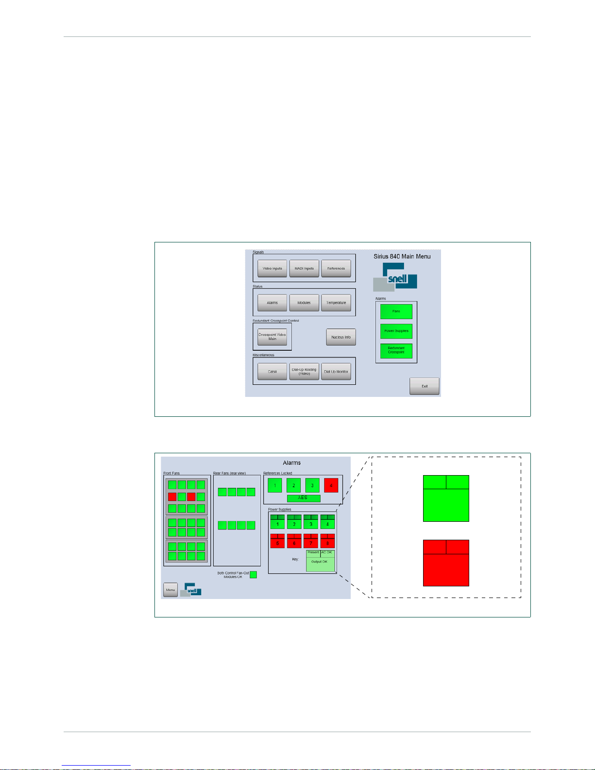
Sirius 840 Installation Manual www.s-a-m.com Testing the Sirius 840
Issue 2 Rev 3 Page 45 © 2016 SAM
10. Testing the Sirius 840
This chapter describes how to test the router to ensure that it can route signals. You will need
at least one video source and a video analyzer to check that the vide o sign al is being passed
correctly.
10.1 Alarms Displayed on the Router Door PC
The Alarms block on the right side of the main menu screen displays the status of the fans,
the power supply shelves and the redundant crosspoint. Live Runner should run
automatically and display a screen similar to Fig 28.
• If a different Live Runner screen is displayed touch the Menu button in the bottom
left corner of the screen to display the main menu screen.
• If Live Runner is not running double tap the Live Runner shortcut on the
Microsoft Windows screen to start it up.
4. Touch the Alarms button on the main menu screen to view the Alarms screen. The
alarms screen displays the router status in more detail (see Fig 29.)
• In the Power Supplies area of the screen, when a PSU shelf is Red, it does not
necessarily mean that the power supply units are faulty. It may just mean that the
PSUs or the alarm cable are not fitted.
• The References Locked block displays the status of the four video reference inputs
and one AES reference that come in on the control rear panel (see Fig 14. on page
27) video reference connectors.
Fig 28. Live Runner Main Menu Screen
Fig 29. Live Runner Alarms Screen
Power Supply Reference
PSU Fitted
PSU Not
Fitted
AC in is
OK
AC in is
not OK
DC out is OK
No DC out
Page 46

Sirius 840 Installation Manual www.s-a-m.com Testing the Sirius 840
Issue 2 Rev 3 Page 46 © 2016 SAM
10.2 Setting a Route Using the Router Door PC
This example uses Video input 1 routed to Video output 2. If you have different input and
output numbers simply substitute the correct numbers when working through the example.
1. Live Runner should run automatically and display a screen similar to Fig 30.
• If a different Live Runner screen is displayed touch the Menu button in the bottom
left corner of the screen to display the main menu screen.
• If Live Runner is not running double tap the shortcut on the Microsoft Windows
screen to start it up.
2. Open the Catsii Control screen on the Door PC (see Fig 31.) by touching the Catsii
button on the Main Menu screen.
3. Ensure the Catsii LEDs are enabled by touching the Global Catsii On button. Set the
Catsii LEDs to signal status mode by touching both of the Normal buttons.
4. Return to the main menu screen by touching the Menu button in the bottom lef t of the
screen.
5. Connect a valid signal source to input 1 on the rea r of th e ro ut er.
6. Check the Catsii LED on input 1 on the rear of the router ch anges from r ed to a nother
color depending on signal standard (see section 10.3).
Fig 30. Live Runner Main Menu Screen
Fig 31. Catsii Control Screen
Page 47

Sirius 840 Installation Manual www.s-a-m.com Testing the Sirius 840
Issue 2 Rev 3 Page 47 © 2016 SAM
7. Route input 1 to output 2 using the Door PC Dial-up Routing Panel (Fig 32.) or other
control mechanism.
8. Touch the Dial-Up Routing (Video) button from the Main Menu screen and then touch
the Continue buttons as they are displayed. Finally touch the Dial-Up button when it
is displayed to access the screen. This procedure avoids the dial-up panel being
enabled accidentally in a live environment.
9. The DST/SRC button toggles between the Destination and Source input (highlighted
with a Red box around the selected text box).
10. Select the Destination text box using the DST/SCR button and enter 2 using the
numeric keypad and the configured destination name is displayed in the Destination
text box.
11. Select the Source text box using the DST/SCR button and enter 1 using the numeric
keypad and the configured source name is displayed in the Source text box.
12. To set the route, touch the Take button.
13. Check the Catsii LED on output 2 on the rear of the router changes from red to the
same color as input 1.
14. Connect output 2 to a signal analyzer and check the signal is correct.
Fig 32. Dial Up Panel
Note:
The source for the currently selected destination is displayed in the Current Source text
box.
Page 48

Sirius 840 Installation Manual www.s-a-m.com Testing the Sirius 840
Issue 2 Rev 3 Page 48 © 2016 SAM
10.3 Signal Status
Catsii LED signal status is driven directly from the input and output modules, and changes
quickly when a Fiber or BNC cable is connected to the Sirius 840.
10.3.1 Video Signal Catsii Colors
Note:
Pulsed means 75% solid color, 25% pulsed color at ~ 1Hz.
Signal Condition - Video Input (5913/5914/5917)
& Output (5923/5924/5926)
Default color
[1]
[1]
You can change these defaults through Centra Workbench.
No valid signal Red
Valid SD signal Yellow
DVB-ASI Signal Yellow - pulsed off
Valid 1080i or 1080p (30 Hz or lower) signal Green
Valid 720p signal Green - pulsed off
Valid 3G signal Blue
Table 5. Default Video Catsii Configuration
Signal Condition - Video Input (5919/5915) & Output (5949/5925) Default color
[1]
[1]
You can change these defaults through Centra Workbench.
No valid signal Red
Valid SD signal with no embedded audio Yellow
Valid SD signal with embedded audio Yellow - pulsed White
DVB-ASI Signal (signal cannot be passed) Yellow - pulsed off
Valid 1080i or 1080p (30 Hz or lower) signal with no embedded audio Green
Valid 1080i or 1080p (30 Hz or lower) signal with embedded audio Green - pulsed White
Valid 720p signal with no embedded audio Green - pulsed off
Valid 720p signal with embedded audio Green - pulsed White
Valid 3G signal with no embedded audio Blue
Valid 3G signal with embedded audio Blue - pulsed White
Table 6. Default Video with Embedded Audio Catsii Configuration
Page 49

Sirius 840 Installation Manual www.s-a-m.com Testing the Sirius 840
Issue 2 Rev 3 Page 49 © 2016 SAM
10.3.2 MADI Audio Catsii Colors
10.4 External Control Input and Output Port Mapping
The Sirius 840 routers are supplied with Workbench, LiveRunne r and a sample/default
database installed on the Door PC. The inst alled sample dat abase is either video only or AHP
depending on the input/output modules fitted.
Table 8. shows the Sirius 840 crosspoint address mapping:
Signal Condition - MADI Input (4915) & Output (4929/4925) Default color
[1]
[1]
You can change these defaults through Centra Workbench.
No valid MADI signal Red
56 Channel MADI @ 48 kHz Yellow - pulsed Off
56 Channel MADI @ 44.1 kHz Yellow - pulsed Blue
56 Channel MADI @ other sample rates Yellow - pulsed Red
Valid 56 Channel MADI Redundant signal (input only) Yellow
64 Channel MADI @ 48 kHz Green - pulsed Off
64 Channel MADI @ 44.1 kHz Green - pulsed Blue
64 Channel MADI @ other sample rates Green - pulsed Red
Valid 64 Channel MADI Redundant signal (input only) Green
T ab le 7. Default Audio Catsii Configurations
Note:
• The information in this section is only correct when the Sirius 840 router control
module(s) are loaded with the sample/default database. Databases can be
modified including the mapping information.
• If the router is shipped with a custom database the mapping may vary but can be
checked and edited using the Workbench software, see the Workbench User
Manual for details.
Input/Output Range Addresses
Video Inputs 1 to 576 Source 0 to 575
Main Video Outputs 1 to 576 Destination 0 to 575
Multiviewer Outputs 1 to 140 Destination 1152 to 1291
Monitoring Outputs 1 to 4 Destination 16370 to 16373
Video Destinations 577 to 1152 are not used and do not respond to any control
Audio Inputs
(Nucleus2 only)
1 to 18432 Source 0 to 18431
Audio Outputs
(Nucleus2 only)
1 to 18432 Destination 0 to 18431
Table 8. Sirius 840 Input and Output Port Mapping
Page 50

Sirius 840 Installation Manual www.s-a-m.com Testing the Sirius 840
Issue 2 Rev 3 Page 50 © 2016 SAM
10.5 Default Serial Port Configuration
When the sample/default database is loaded on the router control module (s) the four RS485
serial communications ports on the rear of the router (see section 6.3) are configured as
shown in Table 9.
If a custom database is loaded on the router control module(s) the ports may be configured
differently. Port configuration can be checked and modified using the Wor kbench software,
see the Workbench User Manual for details.
• RS485 1 (COM 3) = General Switcher In (SW-P-02) for Aurora control
• RS485 2 (COM 4) = General Switcher In (SW-P-02) for Aurora control
• RS485 3 (COM 5) = Panel Protocol for up to 15 controllers on addresses 1 to 16 as
shown in the table below:
• RS485 4 (COM 6) = General Switcher In (SW-P-02) for Aurora control
“Auto” mode has been configured in the default dat abase a s the p rimary refer ence source for
all inputs (see the Sirius 800 User Manual for information on video and audio reference
inputs).
Address Controller Sources Destinations
1 602676, X-Y All All
2 602677, 8 Bus All 1 to 8
3 602677, 6 Bus All 1 to 6
4 602677, 4 Bus All 1 to 4
5 602677, 2 Bus All 1 and 2
6 7028201, 16 x 1 BPX 1 to 16 1
7 7028100, 32 x 1 BPX 1 to 32 2
8 7028000, 48 x 1 BPX 1 to 48 3
9 7028400, Dual 16 x 1 BPX 1 to 16 1 and 2
10 70 28201, 16 x 4 X-Y 1 to 16 1 to 4
11 7028100, 32 x 4 X-Y 1 to 32 1 to 4
12 70 28000, 48 x 4 X-Y 1 to 48 1 to 4
13 7028000, 32 x 16 X-Y 1 to 32 1 to 16
14 7028400, 24 x 12 X-Y 1 to 24 1 to 12
15 Not Used
16 7028400, 16 x 16 X-Y 1 to 16 1 to 16
Table 9. Controllers and Addresses in the Default Database
Page 51

Sirius 840 Installation Manual www.s-a-m.com Testing the Sirius 840
Issue 2 Rev 3 Page 51 © 2016 SAM
10.6 External Control Panels
The Sirius 840 is supplied with a sample/default database. The default database configures
Port 3 to use the Multidrop Communications protocol (SW-P-06). Port 3 supports a variety of
BPX and XY control panels (see Table 9. for details). See section 7.5 for panel connection
information.
10.6.1 Powering Up the Panel
1. Connect the IEC power lead to the rear of the control panel (see section 7.5.2).
2. The control panel will power up and the buttons will go through a start-up sequence.
3. Once the start-up sequence has been completed the buttons will be lit as shown
in Fig 33. on page 51.
4. The control panel is ready to be used.
10.6.1.1 Example: 2RU XY Control Panel Operation
Dial-up XY panel (6026776 mimicking a 6276 control panel).
The following is a brief description of routing a single signal type using an external XY control
panel. A full description of control panel usage can be found in the control panel user manual
1. Press the Destination button so that it displays Cyan (light blue) to indicate that you
are going to select a Destination.
2. Press the Video button then use the numeric keypad to enter the destination port
number that the source is to be switched to.
3. The selected destination details will be displayed in the Destination display.
4. Press the Source button so that it displays Green to indicate that you are going to
select a Source.
5. Press the Video button then use the numer ic keypad to enter the source port number
to be switched.
6. The selected source details will be displayed in the Preset display.
7. Press the Take key to route the selected source to the selected destination.
Fig 33. 2RU XY Control Panel
Page 52

Sirius 840 Installation Manual www.s-a-m.com Testing the Sirius 840
Issue 2 Rev 3 Page 52 © 2016 SAM
Page 53

Sirius 840 Installation Manual www.s-a-m.com Workbench
Issue 2 Rev 3 Page 53 © 2016 SAM
11. Workbench
The Workbench software uses a database to store router and system configuration details.
The Workbench database is written (pushed) to the router controllers to configure the m. Once
the router controllers have been configured in this way they store the database locally
allowing the router to work independently after a power off even if the connection to the
Workbench database PC/server is not available.
The database can be created from scratch, custom built by SAM (chargeable) or based on
one of the supplied sample/default databases. See the Workbench User manual for full
details of Workbench operation and usage.
The following sections describe basic Workbench installation, connecting Workbench to the
router and basic configuration including connecting Workbench to a database.
The router is supplied with Workbench, LiveRunner and a sample database installed on the
Door PC. The installed sample database is either video only or AHP de pending on the
input/output modules fitted.
If one or more LiveRunner clients are to be installed on computers, other than the Door PC,
the database shipped on the Door PC must be moved to a separate Workbench server or
client/server, see section 11.2.3 for details. This does not apply to Workbench clients used for
configuration or to RollCall clients connected to the controller(s).
Although Workbench configuration can be carried out using the Door PC (if a USB mouse and
keyboard are connected) this is not recommend as the screen resolution on the door screen
is relatively low. A Workbench installation DVD is supplied with the router and this can be
used to install a Workbench client on a separate computer which can then be used to
configure the router.
11.1 Installing Workbench
Once the router and the computer(s) are conne cted to a ne twork W orkbe nch can be inst a lled
on the computer(s).
The router is shipped with a Workbench DVD that contains a copy of the Workbench
software. Full installation details, minimum computer specifications and troubleshooting can
be found in the Workbench user manual. Workbench should be installed on a computer that
has access to the router via a network.
1. Insert the Workbench DVD into a suitable co mputer that is connected to the router via
a network.
2. The installation starts automatically. If it doesn’t start browse to the installation DVD
and double click on Workbenchinstaller.exe.
Note:
During the installation, do not close the insta llation wiza rd or the Workbench Install Helper .
Wait until the entire setup process is complete before exiting the install wizard and
Workbench Install Helper.
Page 54

Sirius 840 Installation Manual www.s-a-m.com Workbench
Issue 2 Rev 3 Page 54 © 2016 SAM
3. Follow the prompts to install Workbench.
4. The Choose Components screen is displayed (Fig 34.)
• The greyed out components are mandatory but other components can be ticked
or unticked as required.
• The components chosen will depend on the type of installation being carried out,
for details see Table 10.
• Position the mouse cursor over each component to see a description of its
purpose to the right of the list.
• The installer checks to see whether the component is already installed and only
installs it if the component is not found.
Note:
• If a dialog is displayed that says “Install Checker has stopped working”
administration rights may not have been granted on the computer.
Close the Install Checker dialog and browse to Workbenchinstaller.exe on the
DVD. Right-click on Workbenchinstaller.exe and select Run as administrator
from the menu.
• If Workbench is being installed on a Windows 7 computer then the Windows User
Account Control (UAC) screen will be displayed.
Click Yes and the installation will continue.
• The Windows Installer screen may be displayed, this will depend on which version
of Windows is installed.
Click OK and the installation will continue.
Fig 34. Choose Installation Components
Note:
The actual version numbers of components may differ from those shown.
Page 55

Sirius 840 Installation Manual www.s-a-m.com Workbench
Issue 2 Rev 3 Page 55 © 2016 SAM
5. Click Next > once the installation components have been selected.
6. Follow the prompts to continue with the installation.
Component Description Installation Type:
Client
Client/
Server
Server
MSI 4.5 Microsoft Windows Installer 4.5
NET Framework 3. 5 SP1 NET Framework 3 5 SP1
NET Framework 4 NET Framework 4
Visual C++ 2010 Visual C++ Re-distributable
Windows Powershell Microsoft's task automation framework
that integrates with the .NET
Framework
SQLDBTool Used to backup/restore/create
Databases.
*Only required if SQL Management
Studio is not installed
* *
SQL Server Express Basic SQL Server software.
**Only required if SQL Server is not
installed
** **
Core Files Core Installation files
Workbench Design and configuration files
Live Runner Live control and monitoring
Rules Server Rules server application
Logging Tools Tools and utilities for viewing and
gathering log messages
Example Resources Example screen files and
sample/default databases
Controllers Windows and embedded controller
executable files
Pbak Deploy Tool Used to upgrade software on router
control modules
Documentation Workbench Manual and Getting
Started guide in PDF format
Table 10. Installation Components
Page 56

Sirius 840 Installation Manual www.s-a-m.com Workbench
Issue 2 Rev 3 Page 56 © 2016 SAM
7. When the installation is nearing completion the Configuration Helper will be displayed
in a new window.
The Configuration Helper indicates the status o f each of the W or kbench compon ent s.
The components can be in one of three states:
• Green: The component installed correctly.
• Orange: Optional item that has not been installed.
If the Computer component is Orange it indicates that th e screen resolu tion is not
high enough.
• Red (yellow during update): Required by Workbench but not yet installed.
8. The Workbench Database component will be red as Workbench has not yet been
associated with a database, this is normal.
9. If the Configuration Helper indicates that all other components are installed correctly
(green), click OK. The Configuration Helper screen closes, and the Completing
installation screen displays.
If the Configuration Helper displays components that have not installed (red) these
need to be manually installed before continuing. See the Workben ch User manual for
details.
Fig 35. Configuration Helper
Note:
The Workbench Database component will display red until Workbench is associated with a
Workbench Database.
Note:
If Workbench is run while there are components marked as red, an error message is
displayed.
Page 57

Sirius 840 Installation Manual www.s-a-m.com Workbench
Issue 2 Rev 3 Page 57 © 2016 SAM
10. The Installation will be completed and the following screen is displayed to indicate that
the installation has finished.
11. To stop Workbench starting immediately after installation, uncheck the Launch
Workbench checkbox.
12. Click Finish.
13. Go to section 11.2 for details on associating Workbench with the Workbench
database.
Fig 36. Completing Installation
Page 58

Sirius 840 Installation Manual www.s-a-m.com Workbench
Issue 2 Rev 3 Page 58 © 2016 SAM
11.2 Associating Workbench with the Workbench Database
Workbench requires a working connection to the Workb ench database. Until connected to the
database, the Install Helper displays the connection as red (required by Workbench, but not
yet installed).
There are three options for connecting to a Workbench database:
• Create a new blank database.
• Connect to the existing database on the Door PC (or other PC on the network if the
database has already been installed elsewhere).
• Move the existing database from the router Door PC to a server or client/server and
then connect Workbench to it.
Important:
The Workbench database must be installed on the server. Therefore, unless already
installed, install SQL Server Express and SQL Server Manag ement Studio (or the optional
SQLDBTool) on the server.
Fig 37. Configuration Helper
Important:
• When the Workbench database is installed on the Door PC the Door PC can
support one or more Workbench client s ( configuration only) and/or RollCall clients.
• If one or more LiveRunner client is to be con nected to the Doo r PC the Workbench
database must be hosted on a separate Workbench server or client/server. If the
database is shipped on the Door PC it must be moved to a separate Workbench
server or client/server.
Page 59

Sirius 840 Installation Manual www.s-a-m.com Workbench
Issue 2 Rev 3 Page 59 © 2016 SAM
11.2.1 Create a New Blank Workbench Database
To create a new Workbench Database:
1. Expand the Workbench Database section.
2. Click on the words:
Click here to create databases and permissions.
A command window displays briefly and connects to the database.
3. From the Install Helper, click the Refresh button.
The Workbench Database displays green (installed correctly).
11.2.2 Connect to an Existing Workbench Database
If an existing Workbench database is available, provide the file path, and login credentials:
1. Expand the Workbench Database section. Click on the words:
Click here to alter database connection settings.
The Connection Stri ng Editor dialog box displays.
2. Either, type the server details, or edit the Database Connection String.
3. If using a mirrored server , ente r Failove r Partner backup server details. These details
may be added later. See the Workbench user manual for details.
4. Click OK.
5. From the Install Helper, click the Refresh button.
The Workbench Database displays green (installed correctly).
Note:
Remember all of the Workbench and LiveRunner clients on the system need to be
associated with the database location and this includes W orkbench and Li veRunner on the
Door PC.
Fig 38. Workbench Database Connection Settings
Note:
The Server Name can be an IP address or a name. When using SQL Express (the default
for a standalone PC) the Server Name must also contain an SQL instance name at the
end. For example, the default server name is typically “localhost\SQLEXPRESS”
Page 60

Sirius 840 Installation Manual www.s-a-m.com Workbench
Issue 2 Rev 3 Page 60 © 2016 SAM
11.2.3 Move the Existing Workbench Database from the Router Door PC
1. Ensure Workbench is installed on the server or client server computer that the
Workbench database is to be hosted on, see section 11.1.
2. Backup the Door PC database as described in the Workbench User manual. Th e
backup is carried out from the Workbench computer across the network.
3. Once the backup is complete the database must be re stored to the W orkbench server
or client server computer . The W orkbench datab ase should be restored with the name
“WorkBench”. If the database is restored with a different name the program shortcuts
for Workbench and LiveRunner will need to be updated, see the Workbench User
manual for details on restoring the database and changing the program shortcut
names.
4. Workbench now needs to be associated with the restored database, see section
11.2.2 for details.
11.3 Starting Workbench
Workbench should be associated with the database before it is started for the first time, see
section 11.2.
1. Start Workbench from the Windows Start menu.
Start | All Programs | Snell | MCM | Workbench
2. The first time that Workbench is started the database will need to be updated and the
Database Update screen will be displayed (Fig 39.)
3. Click on the Update Database button.
Note:
Remember all of the Workbench and LiveRunner clients on the system need to be
associated with the new database location and this includes Workbench and LiveRunner
on the Door PC.
Note:
Workbench cannot start without updating the database.
Fig 39. Update Database
Page 61

Sirius 840 Installation Manual www.s-a-m.com Workbench
Issue 2 Rev 3 Page 61 © 2016 SAM
4. Click OK. The login screen displays, see Fig 40.
When Workbench is first installed, there is only are two users, see Table 11.
5. Type the username.
As this is the first login the admin username is recommended as it allows
configuration of both Workbench and the router.
6. Type the associated password, if required.
7. Click on the Login button, or press the Return key. The home screen will be
displayed, see Fig 41.
Fig 40. Login Screen
Username Password
admin admin
user (none required)
Table 11. Default Users
Fig 41. Initial Workbench Administration Screen
Page 62

Sirius 840 Installation Manual www.s-a-m.com Workbench
Issue 2 Rev 3 Page 62 © 2016 SAM
11.4 Adding Router Control Module(s)
This step is only required if Workbench is associated with a Workbench dat abase that doesn’t
contain details of the controllers such as when connecting to a new blank database, as
created in section 11.2.1.
If Workbench is associated with a sample/default or custom database the router control
module(s) will already be configured and will be displayed in the configuration screen, move
on to section 11.5 for details on editing the contro ller conf igu ra tio n s.
1. Click on the Configuration button and the Workbench Configuration screen will be
displayed.
2. Click on the +Add Controller... button on the right of the Workbench Configuration
screen (Fig 42.) and the Controller Wizard screen will start.
3. Select the router control module type fitted to the router from the drop down menu.
Nucleus2 2463 - select Centra Controller (2330/246x/PC)
Nucleus 2450 - select Nucleus Controller (2450)
4. When starting with a new blank database select the radio button for:
I want to create a new configuration to push to a controller that is on the
network
See the Workbench user manual for details of the other options.
Fig 42. Workbench Configuration Screen
Fig 43. Controller Wizard Screen
Page 63

Sirius 840 Installation Manual www.s-a-m.com Workbench
Issue 2 Rev 3 Page 63 © 2016 SAM
5. When the controller type and setup type have been selected click the Next button.
6. Enter the Name, IP address and IP Port for the main controller and, if the router
contains two router control modules, tick the Create Pair checkbox.
Name - Enter the controller name to be displayed by Workbench
IP Address - Edit the controller IP address to match the main router control modu le .
IP Port - Enter the controller IP port address, this is usually 2007
Create Pair - Tick the Create Pair checkbox to enter details of the second router
control module if one is fitted.
Workbench automatically sets the IP address to be xxx.xxx.xxx.xx+1
where xxx.xxx.xxx.xxx = main controller IP address.
Fig 44. Controller Wizard Network Configuration Screen
Page 64

Sirius 840 Installation Manual www.s-a-m.com Workbench
Issue 2 Rev 3 Page 64 © 2016 SAM
7. Click the Next button.
8. Select the Use a Factory Or User Default radio button.
9. Select the correct router type from the Router Type drop down list, S800 for the
Sirius 840 router.
10. Select the router configuration closest to the one required from the
Router Configuration drop-down list.
11. Tick the Import information to allow editing of hardware panel configurations
checkbox.
12. Click the Next button.
Fig 45. Controller Wizard Router Configuration Screen
Note:
The No Default option is used when installing a new system similar to a previously
installed one. The existing configuration is then copied as a basis for the configuration of
the new controller.
Page 65

Sirius 840 Installation Manual www.s-a-m.com Workbench
Issue 2 Rev 3 Page 65 © 2016 SAM
13. A summary screen is displayed (Fig 46.). If any of the parameters on this screen are
incorrect, click the Previous button to return to the screen that requires amendment.
edit the details, and continue through the Controller Wizard as before.
14. Confirm all of the configuration details are correct and click on the Finish button.
15. The controllers are added to the Workbench Configura tion screen.
Fig 47. shows an example screen for both cont ro llers and Table 12. describes the status of
the controllers in the example. For full details of the status displays see the Workbench User
manual.
Fig 46. Controller Wizard Summary Screen
Fig 47. Controllers Added to Controller Configuration Screen
Column
Example
Status
Description
Connected Both controllers are pres en t an d co nn ec te d cor re ct l y
Checksum Configuration Match, both databases are identical.
Primary Primary The controller named Sirius840A is the primary (main) controller.
Active
Active
Inactive
The controller named Sirius840A is Active (controlling the router).
The controller named Sirius 840Slave is Inactive ready to take over
from the active controller in the event of a problem.
Table 12. Controller Status Example
Page 66

Sirius 840 Installation Manual www.s-a-m.com Workbench
Issue 2 Rev 3 Page 66 © 2016 SAM
11.5 Controller Configuration
There are three methods of configuring the router control module and an example of each is
described in the following sections.
1. Select the inactive controller and click on the Edit Controller Config... button. The
Controller Configuration window is displayed, see Fig 48.
The Controller Configuration screen is displayed with the Devices tab open. The Tabs on this
screen are shown below, see the Workbench User manual for full details:
• Devices - Nucleus router control modules have default devices already selected.
• Routers - Basic configuration of the router, see section 11.5.1 for an example.
• Local Router Hardware - Additional configuration required when configuring a
Nucleus2 2463 router control module.
• Generic - The Generic Editor (see section 11.5.2) and Generic Online Editor (see
section 11.5.3) tools are accessed from this tab. They allow advanced configuration
changes to be made using a logical tree structure format.
Note:
• If the router contains two router control modules the inactive controller should be
configured first and once that process is comple te th e ot he r co ntr o lle r is made
inactive and the configuration changes can be copied to it.
• On a dual redundant controller system the router controllers can be configured
while the router is on-air, if required.
• If the router only has a single controller then this can be configured while the router
is on-air but all communication with the router controller will be lost during the
database push of the configuration changes and subsequent reset. Because of this
the crosspoints cannot be switched and tallies are not reported during this process.
Video and audio processing is unaffected.
Fig 48. Controller Configuration (Nucleus2 2463 Shown)
Page 67

Sirius 840 Installation Manual www.s-a-m.com Workbench
Issue 2 Rev 3 Page 67 © 2016 SAM
11.5.1 Configuration Using the Workbench Configuration Screens
The Workbench configuration screens are used to view and edit the router control module
configuration settings (see Fig 49.)
To configure the router control module from the Workbench configuration screens:
1. Click on the Routers tab from the Controller Configuration screen. The Routers tab
shows the currently configured router matrices, buttons for basic configuration
settings and a button to open the advanced configuration options.
2. Make any changes required using the menu buttons and click the Close button.
3. Any configuration changes must be pushed from the Workbench computer to the
router control module. See section for 11.5.4 details.
Fig 49. Router Configuration (Nucleus2 2463 Shown)
Note:
In the example shown in Fig 49. the router control module is configured with a video matrix
(S840V) and an audio matrix (S840A).
Page 68

Sirius 840 Installation Manual www.s-a-m.com Workbench
Issue 2 Rev 3 Page 68 © 2016 SAM
Example Setting a Switch Point Reference for a Video Input
The following examples describe how to select the switch point reference for one or more of
the video inputs in the matrix. For information on references and switch points see the Sirius
800 User Manual.
1. From the Routers tab click on the Advanced Configuration expand button and
then click the References... button.
2. The Switch Point Editor screen is displayed.
3. The switch points can be selected individua lly for each inpu t or all of th e input s can be
set to use the same switch point reference.
Setting an Individual Switch Point for a Video Input
1. Select the video input to be set by clicking on it. Once selected open the drop down
list as shown in Fig 50.
2. Select the required Switch Point for the input from the drop down list.
3. Repeat as required for the other inputs and then click the OK button to finish.
4. Any configuration changes must be pushed from the Workbench computer to the
router control module. See section for 11.5.4 details.
Setting a Common Switch Point for all Video Inputs
1. Select the switch point for all of the video inputs by opening the Set drop down list at
the bottom of the Switch Point Editor screen.
2. Click the Set All button to assign the selected switch point to all of the video inputs in
the matrix.
3. Any configuration changes must be pushed from the Workbench computer to the
router control module. See section for 11.5.4 details.
Fig 50. Switch Point Editor (Nu cleus2 2463 Shown)
Note:
This setting will overwrite any individual selections already made.
Page 69

Sirius 840 Installation Manual www.s-a-m.com Workbench
Issue 2 Rev 3 Page 69 © 2016 SAM
11.5.2 Configuration Using the Generic Configuration Editor
The Generic Configuration Editor is used to edit a router control module in a logical tree
structure format, see Fig 51. It can be used to edit or view the controller configuration. The
Generic Configuration Editor is useful for grabbing DCCP elements for screen design.
To configure the router control module using the Generic Configuration Editor:
1. Click on the Generic tab from the Controller Configuration screen shown on page 66
in Fig 48.
2. Click on the Edit Controller... button to display the Generic Configuration Editor,
Fig 51.
The controller’s configuration parameters display in a tree.
• Click on a symbol to expand the node below it.
• Click on a symbol to collapse the node.
The nodes depend on the type of device.
Fig 51. Generic Configuration Editor (Offline)
Important:
Care should be taken when using the Generic Configuration Editor. It is very easy to
change the configuration so that the router control module no longer functions correctly,
and in a way that is difficult to fault-find. For example, changing the baud rate can stop the
controller from communicating correctly, if a device has not had the same change in baud
rate.
Important:
Removing an item from the middle of an array can ‘break’ the controller and links to soft
panels.
Page 70

Sirius 840 Installation Manual www.s-a-m.com Workbench
Issue 2 Rev 3 Page 70 © 2016 SAM
3. Select the parameter to be configured and make the change(s) required.
There are three types of controls used to build the configuration. Depending on the selection,
the appropriate control displays at the bottom of the screen, see Table 13. and Fig 51.
4. Click on the Apply button to apply each change made to the configuration.
5. Once complete click on the OK button to close the window.
6. Any configuration changes must be pushed from the Workbench computer to the
router control module. See section for 11.5.4 details.
11.5.3 Configuration Using the Generic Online Configuration Editor
The Generic Online Configuration Editor displays the current configuration status of the live
system. It is mainly used for diagnostic purposes to identify failures. The display and editing of
the Generic Online Configuration Editor is similar to that for the Generic Configuration Editor,
see section 11.5.2.
To configure the router control module using the Generic Editor:
1. Click on the Generic tab from the Controller Configuration screen shown in Fig 48.
2. Click on the Edit Controller Online... button to display the Generic Online Editor.
3. As changes are applied in real-time they do not need to be pushed to the router
control module.
Control Description
Plus/Minus symbols These controls add or remove an element below the selected
node.
Drop-down lists If the selected configuration parameter is defined by a set group of
choices, a drop-down list enables the value to be selected.
Text boxes If the selected configuration parameter requires a name, a text
box enables the name to be entered.
Table 13. Gene ric Configuration Controls
Important:
Any changes made to the configuration in the Online Editor occur in real-time on a live
controller. It is generally recommended that configuration changes are made using the
Generic Configuration Editor.
Page 71

Sirius 840 Installation Manual www.s-a-m.com Workbench
Issue 2 Rev 3 Page 71 © 2016 SAM
11.5.4 Pushing the Configuration to the Controller(s)
Any configuration changes must be pushed from the Workbench computer to the router
control module(s) so that the controller(s) can use the new configuration.
The configuration changes are first pushed to the modified inactive controller and it is then
made active. The changes are then copied to the unmodified inactive controller (was active)
and pushed to it. This then means that both controllers contain the same configuration as the
Workbench database.
In a frame with a single controller this is not possible and the database must be pushed to the
single active controller. All communication with the router controller will be lost during the
database push of the configuration changes and subsequent reset. Because of this the
crosspoints cannot be switched and tallies are not reported during this process. Video and
audio processing is unaffected.
1. With the modified controller selected click on the Push to Controller(s) button.
2. The Workbench controller Connected status icon will return to the connected state
once the database push and reset have been completed.
3. The active unmodified controller must be must now be made inactive. Select the
active controller and click on the Reset button on the right of the Workbench screen.
4. The active controller will become the inactive controller and the modified controller will
become the active controller.
5. Select the active updated controller and click on the Copy config to Partner button.
This will push the updated configuration to the inactive controller.
6. The Workbench controller Connected status icon will return to the connected state
once the database push and reset have been completed.
7. Both controllers will now contain the same configuration as the Workbench database
as indicated by the Checksum status icon
Note:
In a router equipped with a single controller the configuration change is now complete.
Page 72

Sirius 840 Installation Manual www.s-a-m.com Workbench
Issue 2 Rev 3 Page 72 © 2016 SAM
 Loading...