


User Instruction Manual
IQUDC30
3G/HD/SD-SDI Up, Down, Cross Converter with Frame Synchronizer
IQUDC31
Dual-channel 3G/HD/SD-SDI Up, Down, Cross Converter with
Frame Synchronizer
IQUDC32
3G/HD/SD-SDI Up, Down, Cross Converter with Frame Synchronizer
and AES I/O
IQUDC33
Dual-channel 3G/HD/SD-SDI Up, Down, Cross Converter with
Frame Synchronizer and AES I/O
www.s-a-m.com

IQUDC30/IQUDC31/IQUDC32/IQUDC33 Information and Notices
Information and Notices
Copyright and Disclaimer
Copyright protection claimed includes all forms and matters of copyrightable material and
information now allowed by statutory or judicial law or hereinafter granted, including without
limitation, material generated from the software programs which are displayed on the screen
such as icons, screen display looks etc.
Information in this manual and software are subject to change without notice and does not
represent a commitment on the part of SAM. The software described in this manual is
furnished under a license agreement and can not be reproduced or copied in any manner
without prior agreement with SAM or their authorized agents.
Reproduction or disassembly of embedded computer programs or algorithms pr ohibited.
No part of this publication can be transmitted or reproduced in any form or by any means,
electronic or mechanical, including photocopy, recording or any information storage and
retrieval system, without permission being granted, in writing, by the publishers or their
authorized agents.
SAM operates a policy of continuous improvement and development. SAM reserves the r ight
to make changes and improvements to any of the products described in this document
without prior notice.
Contact Det ails
Customer Support
For details of our Regional Customer Support Offices, please visit the SAM website and
navigate to Support/Contact Support.
www.s-a-m.com/support/contact-support/
Customers with a support contract should call their persona lized number, which ca n be found
in their contract, and be ready to provide their contract number and details.
Issue 1 Rev 4 Page 2 © 2016 SAM

IQUDC30/IQUDC31/IQUDC32/IQUDC33
Contents
Information and Notices . . . . . . . . . . . . . . . . . . . . . . . . . . . . . . . . . . . . . . . . . . . . . . . . 2
Copyright and Disclaimer . . . . . . . . . . . . . . . . . . . . . . . . . . . . . . . . . . . . . . . . . . . . . . 2
Contact Details . . . . . . . . . . . . . . . . . . . . . . . . . . . . . . . . . . . . . . . . . . . . . . . . . . . . . . 2
1 Introduction . . . . . . . . . . . . . . . . . . . . . . . . . . . . . . . . . . . . . . . . . . . . . . . . . . . . . . . . . 7
1.1 Description . . . . . . . . . . . . . . . . . . . . . . . . . . . . . . . . . . . . . . . . . . . . . . . . . . . . . . 7
1.2 Block Diagrams. . . . . . . . . . . . . . . . . . . . . . . . . . . . . . . . . . . . . . . . . . . . . . . . . . . 7
1.2.1 IQUDC30 and IQUDC32. . . . . . . . . . . . . . . . . . . . . . . . . . . . . . . . . . . . . . . . 7
1.2.2 IQUDC31 and IQUDC33. . . . . . . . . . . . . . . . . . . . . . . . . . . . . . . . . . . . . . . . 8
1.3 Features . . . . . . . . . . . . . . . . . . . . . . . . . . . . . . . . . . . . . . . . . . . . . . . . . . . . . . . . 9
1.4 Order Codes . . . . . . . . . . . . . . . . . . . . . . . . . . . . . . . . . . . . . . . . . . . . . . . . . . . . 10
1.4.1 Hardware Options . . . . . . . . . . . . . . . . . . . . . . . . . . . . . . . . . . . . . . . . . . . . 10
1.4.2 Software Options. . . . . . . . . . . . . . . . . . . . . . . . . . . . . . . . . . . . . . . . . . . . . .11
1.4.3 SFP Options . . . . . . . . . . . . . . . . . . . . . . . . . . . . . . . . . . . . . . . . . . . . . . . . 12
1.5 Rear Panels. . . . . . . . . . . . . . . . . . . . . . . . . . . . . . . . . . . . . . . . . . . . . . . . . . . . . 13
1.5.1 IQUDC30. . . . . . . . . . . . . . . . . . . . . . . . . . . . . . . . . . . . . . . . . . . . . . . . . . . 13
1.5.2 IQUDC31. . . . . . . . . . . . . . . . . . . . . . . . . . . . . . . . . . . . . . . . . . . . . . . . . . . 14
1.5.3 IQUDC32. . . . . . . . . . . . . . . . . . . . . . . . . . . . . . . . . . . . . . . . . . . . . . . . . . . 15
1.5.4 IQUDC33. . . . . . . . . . . . . . . . . . . . . . . . . . . . . . . . . . . . . . . . . . . . . . . . . . . 16
1.6 Enclosures. . . . . . . . . . . . . . . . . . . . . . . . . . . . . . . . . . . . . . . . . . . . . . . . . . . . . . 17
1.6.1 B-style Enclosure . . . . . . . . . . . . . . . . . . . . . . . . . . . . . . . . . . . . . . . . . . . . 17
1.6.2 A-style Enclosures. . . . . . . . . . . . . . . . . . . . . . . . . . . . . . . . . . . . . . . . . . . . 17
2 Technical Specification. . . . . . . . . . . . . . . . . . . . . . . . . . . . . . . . . . . . . . . . . . . . . . . 18
3 Connections. . . . . . . . . . . . . . . . . . . . . . . . . . . . . . . . . . . . . . . . . . . . . . . . . . . . . . . . 23
3.1 IQUDC3000-1A(B)3 . . . . . . . . . . . . . . . . . . . . . . . . . . . . . . . . . . . . . . . . . . . . . . 23
3.1.1 SDI Inputs . . . . . . . . . . . . . . . . . . . . . . . . . . . . . . . . . . . . . . . . . . . . . . . . . . 23
3.1.2 SDI Outputs. . . . . . . . . . . . . . . . . . . . . . . . . . . . . . . . . . . . . . . . . . . . . . . . . 23
3.1.3 Reference Input. . . . . . . . . . . . . . . . . . . . . . . . . . . . . . . . . . . . . . . . . . . . . . 23
3.2 IQUDC3001-1B3. . . . . . . . . . . . . . . . . . . . . . . . . . . . . . . . . . . . . . . . . . . . . . . . . 24
3.2.1 SDI Inputs . . . . . . . . . . . . . . . . . . . . . . . . . . . . . . . . . . . . . . . . . . . . . . . . . . 24
3.2.2 SDI Outputs. . . . . . . . . . . . . . . . . . . . . . . . . . . . . . . . . . . . . . . . . . . . . . . . . 24
3.2.3 GPIO . . . . . . . . . . . . . . . . . . . . . . . . . . . . . . . . . . . . . . . . . . . . . . . . . . . . . . 24
3.3 IQUDC3002-1A(B)3 . . . . . . . . . . . . . . . . . . . . . . . . . . . . . . . . . . . . . . . . . . . . . . 24
3.3.1 SDI Inputs . . . . . . . . . . . . . . . . . . . . . . . . . . . . . . . . . . . . . . . . . . . . . . . . . . 24
3.3.2 SDI Outputs. . . . . . . . . . . . . . . . . . . . . . . . . . . . . . . . . . . . . . . . . . . . . . . . . 24
3.3.3 Reference Input. . . . . . . . . . . . . . . . . . . . . . . . . . . . . . . . . . . . . . . . . . . . . . 24
3.3.4 SFP . . . . . . . . . . . . . . . . . . . . . . . . . . . . . . . . . . . . . . . . . . . . . . . . . . . . . . . 25
3.4 IQUDC3003-1B3. . . . . . . . . . . . . . . . . . . . . . . . . . . . . . . . . . . . . . . . . . . . . . . . . 25
3.4.1 SDI Inputs . . . . . . . . . . . . . . . . . . . . . . . . . . . . . . . . . . . . . . . . . . . . . . . . . . 25
3.4.2 SDI Outputs. . . . . . . . . . . . . . . . . . . . . . . . . . . . . . . . . . . . . . . . . . . . . . . . . 25
3.4.3 SFP . . . . . . . . . . . . . . . . . . . . . . . . . . . . . . . . . . . . . . . . . . . . . . . . . . . . . . . 25
3.5 IQUDC3100-1B3. . . . . . . . . . . . . . . . . . . . . . . . . . . . . . . . . . . . . . . . . . . . . . . . . 25
3.5.1 SDI Inputs . . . . . . . . . . . . . . . . . . . . . . . . . . . . . . . . . . . . . . . . . . . . . . . . . . 25
3.5.2 SDI Outputs. . . . . . . . . . . . . . . . . . . . . . . . . . . . . . . . . . . . . . . . . . . . . . . . . 25
3.5.3 Reference Input. . . . . . . . . . . . . . . . . . . . . . . . . . . . . . . . . . . . . . . . . . . . . . 26
3.6 IQUDC3101-1B3. . . . . . . . . . . . . . . . . . . . . . . . . . . . . . . . . . . . . . . . . . . . . . . . . 27
3.6.1 SDI Inputs . . . . . . . . . . . . . . . . . . . . . . . . . . . . . . . . . . . . . . . . . . . . . . . . . . 27
3.6.2 SDI Outputs. . . . . . . . . . . . . . . . . . . . . . . . . . . . . . . . . . . . . . . . . . . . . . . . . 27
3.6.3 GPIO . . . . . . . . . . . . . . . . . . . . . . . . . . . . . . . . . . . . . . . . . . . . . . . . . . . . . . 27
3.7 IQUDC3102-1B3. . . . . . . . . . . . . . . . . . . . . . . . . . . . . . . . . . . . . . . . . . . . . . . . . 27
3.7.1 SDI Inputs . . . . . . . . . . . . . . . . . . . . . . . . . . . . . . . . . . . . . . . . . . . . . . . . . . 27
3.7.2 SDI Outputs. . . . . . . . . . . . . . . . . . . . . . . . . . . . . . . . . . . . . . . . . . . . . . . . . 27
3.7.3 Reference Inputs. . . . . . . . . . . . . . . . . . . . . . . . . . . . . . . . . . . . . . . . . . . . . 27
3.7.4 SFP . . . . . . . . . . . . . . . . . . . . . . . . . . . . . . . . . . . . . . . . . . . . . . . . . . . . . . . 28
3.8 IQUDC3103-1B3. . . . . . . . . . . . . . . . . . . . . . . . . . . . . . . . . . . . . . . . . . . . . . . . . 28
3.8.1 SDI Inputs . . . . . . . . . . . . . . . . . . . . . . . . . . . . . . . . . . . . . . . . . . . . . . . . . . 28
Issue 1 Rev 4 Page 3 © 2016 SAM

IQUDC30/IQUDC31/IQUDC32/IQUDC33
3.8.2 SDI Outputs. . . . . . . . . . . . . . . . . . . . . . . . . . . . . . . . . . . . . . . . . . . . . . . . . 28
3.8.3 SFP . . . . . . . . . . . . . . . . . . . . . . . . . . . . . . . . . . . . . . . . . . . . . . . . . . . . . . . 28
3.9 IQUDC3200-2A(B)3 . . . . . . . . . . . . . . . . . . . . . . . . . . . . . . . . . . . . . . . . . . . . . . 28
3.9.1 SDI Inputs . . . . . . . . . . . . . . . . . . . . . . . . . . . . . . . . . . . . . . . . . . . . . . . . . . 28
3.9.2 SDI Outputs. . . . . . . . . . . . . . . . . . . . . . . . . . . . . . . . . . . . . . . . . . . . . . . . . 28
3.9.3 Reference Input. . . . . . . . . . . . . . . . . . . . . . . . . . . . . . . . . . . . . . . . . . . . . . 29
3.10 IQUDC3202-2A(B)3 . . . . . . . . . . . . . . . . . . . . . . . . . . . . . . . . . . . . . . . . . . . . . 29
3.10.1 SDI Inputs . . . . . . . . . . . . . . . . . . . . . . . . . . . . . . . . . . . . . . . . . . . . . . . . . 29
3.10.2 SDI Outputs. . . . . . . . . . . . . . . . . . . . . . . . . . . . . . . . . . . . . . . . . . . . . . . . 29
3.10.3 AES Inputs/Outputs. . . . . . . . . . . . . . . . . . . . . . . . . . . . . . . . . . . . . . . . . . 29
3.10.4 Reference Input. . . . . . . . . . . . . . . . . . . . . . . . . . . . . . . . . . . . . . . . . . . . . 29
3.10.5 SFP . . . . . . . . . . . . . . . . . . . . . . . . . . . . . . . . . . . . . . . . . . . . . . . . . . . . . . 30
3.11 IQUDC3203-2A(B)3. . . . . . . . . . . . . . . . . . . . . . . . . . . . . . . . . . . . . . . . . . . . . . 30
3.11.1 SDI Inputs . . . . . . . . . . . . . . . . . . . . . . . . . . . . . . . . . . . . . . . . . . . . . . . . . 30
3.11.2 SDI Outputs. . . . . . . . . . . . . . . . . . . . . . . . . . . . . . . . . . . . . . . . . . . . . . . . 30
3.1 1.3 GPIO . . . . . . . . . . . . . . . . . . . . . . . . . . . . . . . . . . . . . . . . . . . . . . . . . . . . . 30
3.11.4 Reference Input. . . . . . . . . . . . . . . . . . . . . . . . . . . . . . . . . . . . . . . . . . . . . 30
3.1 1.5 SFP . . . . . . . . . . . . . . . . . . . . . . . . . . . . . . . . . . . . . . . . . . . . . . . . . . . . . . 31
3.11.6 AES Inputs/Outputs. . . . . . . . . . . . . . . . . . . . . . . . . . . . . . . . . . . . . . . . . . 31
3.12 IQUDC3300-2A(B)3 . . . . . . . . . . . . . . . . . . . . . . . . . . . . . . . . . . . . . . . . . . . . . 32
3.12.1 SDI Inputs . . . . . . . . . . . . . . . . . . . . . . . . . . . . . . . . . . . . . . . . . . . . . . . . . 32
3.12.2 SDI Outputs. . . . . . . . . . . . . . . . . . . . . . . . . . . . . . . . . . . . . . . . . . . . . . . . 32
3.12.3 Reference Input. . . . . . . . . . . . . . . . . . . . . . . . . . . . . . . . . . . . . . . . . . . . . 32
3.13 IQUDC3302-2A(B)3 . . . . . . . . . . . . . . . . . . . . . . . . . . . . . . . . . . . . . . . . . . . . . 33
3.13.1 SDI Inputs . . . . . . . . . . . . . . . . . . . . . . . . . . . . . . . . . . . . . . . . . . . . . . . . . 33
3.13.2 SDI Outputs. . . . . . . . . . . . . . . . . . . . . . . . . . . . . . . . . . . . . . . . . . . . . . . . 33
3.13.3 AES Inputs/Outputs. . . . . . . . . . . . . . . . . . . . . . . . . . . . . . . . . . . . . . . . . . 33
3.13.4 Reference Input. . . . . . . . . . . . . . . . . . . . . . . . . . . . . . . . . . . . . . . . . . . . . 33
3.13.5 SFP . . . . . . . . . . . . . . . . . . . . . . . . . . . . . . . . . . . . . . . . . . . . . . . . . . . . . . 33
3.14 IQUDC3303-2A(B)3 . . . . . . . . . . . . . . . . . . . . . . . . . . . . . . . . . . . . . . . . . . . . . 34
3.14.1 SDI Inputs . . . . . . . . . . . . . . . . . . . . . . . . . . . . . . . . . . . . . . . . . . . . . . . . . 34
3.14.2 SDI Outputs. . . . . . . . . . . . . . . . . . . . . . . . . . . . . . . . . . . . . . . . . . . . . . . . 34
3.14.3 GPIO . . . . . . . . . . . . . . . . . . . . . . . . . . . . . . . . . . . . . . . . . . . . . . . . . . . . . 34
3.14.4 Reference Input. . . . . . . . . . . . . . . . . . . . . . . . . . . . . . . . . . . . . . . . . . . . . 34
3.14.5 SFP . . . . . . . . . . . . . . . . . . . . . . . . . . . . . . . . . . . . . . . . . . . . . . . . . . . . . . 34
3.14.6 AES Inputs/Outputs. . . . . . . . . . . . . . . . . . . . . . . . . . . . . . . . . . . . . . . . . . 35
4 Card Edge LEDs . . . . . . . . . . . . . . . . . . . . . . . . . . . . . . . . . . . . . . . . . . . . . . . . . . . . 36
5 Operation Using the RollCall Control Panel . . . . . . . . . . . . . . . . . . . . . . . . . . . . . . 37
5.1 Information Window. . . . . . . . . . . . . . . . . . . . . . . . . . . . . . . . . . . . . . . . . . . . . . . 37
5.1.1 Video Input Status. . . . . . . . . . . . . . . . . . . . . . . . . . . . . . . . . . . . . . . . . . . . 37
5.1.2 Video Output Status . . . . . . . . . . . . . . . . . . . . . . . . . . . . . . . . . . . . . . . . . . 37
5.1.3 Audio Status . . . . . . . . . . . . . . . . . . . . . . . . . . . . . . . . . . . . . . . . . . . . . . . . 38
5.1.4 Reference Status. . . . . . . . . . . . . . . . . . . . . . . . . . . . . . . . . . . . . . . . . . . . . 38
5.2 Input . . . . . . . . . . . . . . . . . . . . . . . . . . . . . . . . . . . . . . . . . . . . . . . . . . . . . . . . . . 39
5.2.1 Input Source Ch 1 and Ch 2 . . . . . . . . . . . . . . . . . . . . . . . . . . . . . . . . . . . . 39
5.3 Output-Ch1 and Ch2. . . . . . . . . . . . . . . . . . . . . . . . . . . . . . . . . . . . . . . . . . . . . . 40
5.3.1 Output Standard . . . . . . . . . . . . . . . . . . . . . . . . . . . . . . . . . . . . . . . . . . . . . 40
5.3.2 Default Output. . . . . . . . . . . . . . . . . . . . . . . . . . . . . . . . . . . . . . . . . . . . . . . 41
5.3.3 Scrolling Caption Generator . . . . . . . . . . . . . . . . . . . . . . . . . . . . . . . . . . . . 41
5.3.4 Freeze. . . . . . . . . . . . . . . . . . . . . . . . . . . . . . . . . . . . . . . . . . . . . . . . . . . . . 41
5.3.5 Legalization. . . . . . . . . . . . . . . . . . . . . . . . . . . . . . . . . . . . . . . . . . . . . . . . . 42
5.3.6 SFP Output Routing . . . . . . . . . . . . . . . . . . . . . . . . . . . . . . . . . . . . . . . . . . 42
5.3.7 Test Patterns. . . . . . . . . . . . . . . . . . . . . . . . . . . . . . . . . . . . . . . . . . . . . . . . 42
5.3.8 Blanking . . . . . . . . . . . . . . . . . . . . . . . . . . . . . . . . . . . . . . . . . . . . . . . . . . . 43
5.3.9 Luma Clipper. . . . . . . . . . . . . . . . . . . . . . . . . . . . . . . . . . . . . . . . . . . . . . . . 43
5.3.10 Logo Control (Option) . . . . . . . . . . . . . . . . . . . . . . . . . . . . . . . . . . . . . . . . 44
5.4 Video-Ch1 and Ch2. . . . . . . . . . . . . . . . . . . . . . . . . . . . . . . . . . . . . . . . . . . . . . . 46
5.4.1 Proc Amp . . . . . . . . . . . . . . . . . . . . . . . . . . . . . . . . . . . . . . . . . . . . . . . . . . 46
Issue 1 Rev 4 Page 4 © 2016 SAM

IQUDC30/IQUDC31/IQUDC32/IQUDC33
5.4.2 Nonlinear Enhancer . . . . . . . . . . . . . . . . . . . . . . . . . . . . . . . . . . . . . . . . . . 47
5.4.3 Conversion Aperture . . . . . . . . . . . . . . . . . . . . . . . . . . . . . . . . . . . . . . . . . . 48
5.4.4 Noise Reduction (Option) . . . . . . . . . . . . . . . . . . . . . . . . . . . . . . . . . . . . . . 48
5.5 Convert-Ch1 and Ch2 . . . . . . . . . . . . . . . . . . . . . . . . . . . . . . . . . . . . . . . . . . . . . 50
5.5.1 Up Conversion . . . . . . . . . . . . . . . . . . . . . . . . . . . . . . . . . . . . . . . . . . . . . . 50
5.5.2 Motion Processing. . . . . . . . . . . . . . . . . . . . . . . . . . . . . . . . . . . . . . . . . . . . 50
5.5.3 Enhanced Film Mode . . . . . . . . . . . . . . . . . . . . . . . . . . . . . . . . . . . . . . . . . 51
5.5.4 Input Cadence. . . . . . . . . . . . . . . . . . . . . . . . . . . . . . . . . . . . . . . . . . . . . . . 51
5.5.5 Output Cadence . . . . . . . . . . . . . . . . . . . . . . . . . . . . . . . . . . . . . . . . . . . . . 52
5.6 ARC & Sidebar Keyer-Ch1 and Ch2 . . . . . . . . . . . . . . . . . . . . . . . . . . . . . . . . . . 53
5.6.1 Sync Mode . . . . . . . . . . . . . . . . . . . . . . . . . . . . . . . . . . . . . . . . . . . . . . . . . 54
5.6.2 Aspect Signaling Control Enable. . . . . . . . . . . . . . . . . . . . . . . . . . . . . . . . . 54
5.6.3 Signaling Detected . . . . . . . . . . . . . . . . . . . . . . . . . . . . . . . . . . . . . . . . . . . 54
5.6.4 Sidebar Keying & Output Crop (Option) . . . . . . . . . . . . . . . . . . . . . . . . . . . 54
5.6.5 Post Scaling Control . . . . . . . . . . . . . . . . . . . . . . . . . . . . . . . . . . . . . . . . . . 55
5.6.6 Standard Presets When No Aspect Signaling. . . . . . . . . . . . . . . . . . . . . . . 56
5.6.7 Aspect Signaling Control – Scaling Control. . . . . . . . . . . . . . . . . . . . . . . . . 58
5.6.8 Input Signaling ARC Conversions. . . . . . . . . . . . . . . . . . . . . . . . . . . . . . . . 59
5.6.9 Aspect Signaling Control – Signaling Config. . . . . . . . . . . . . . . . . . . . . . . . 61
5.6.10 Aspect Signaling Control – Force Output Signaling Setup . . . . . . . . . . . . 65
5.6.11 ARC Memories . . . . . . . . . . . . . . . . . . . . . . . . . . . . . . . . . . . . . . . . . . . . . 66
5.7 Audio Routing-Ch1 and Ch2 . . . . . . . . . . . . . . . . . . . . . . . . . . . . . . . . . . . . . . . . 68
5.7.1 Input Pairs. . . . . . . . . . . . . . . . . . . . . . . . . . . . . . . . . . . . . . . . . . . . . . . . . . 68
5.7.2 Process Pairs . . . . . . . . . . . . . . . . . . . . . . . . . . . . . . . . . . . . . . . . . . . . . . . 69
5.8 Audio Shuffle-Ch1 and Ch2. . . . . . . . . . . . . . . . . . . . . . . . . . . . . . . . . . . . . . . . . 70
5.8.1 Process Pairs . . . . . . . . . . . . . . . . . . . . . . . . . . . . . . . . . . . . . . . . . . . . . . . 70
5.8.2 Output Pairs . . . . . . . . . . . . . . . . . . . . . . . . . . . . . . . . . . . . . . . . . . . . . . . . 70
5.8.3 Channel-based Routing Rules . . . . . . . . . . . . . . . . . . . . . . . . . . . . . . . . . . 71
5.8.4 Invert Phase . . . . . . . . . . . . . . . . . . . . . . . . . . . . . . . . . . . . . . . . . . . . . . . . 72
5.8.5 Control. . . . . . . . . . . . . . . . . . . . . . . . . . . . . . . . . . . . . . . . . . . . . . . . . . . . . 72
5.9 Audio Control-Ch1 and Ch2 . . . . . . . . . . . . . . . . . . . . . . . . . . . . . . . . . . . . . . . . 73
5.9.1 Gain. . . . . . . . . . . . . . . . . . . . . . . . . . . . . . . . . . . . . . . . . . . . . . . . . . . . . . . 73
5.9.2 Tone Frequency . . . . . . . . . . . . . . . . . . . . . . . . . . . . . . . . . . . . . . . . . . . . . 73
5.9.3 Delay. . . . . . . . . . . . . . . . . . . . . . . . . . . . . . . . . . . . . . . . . . . . . . . . . . . . . . 74
5.10 Audio I/O AES. . . . . . . . . . . . . . . . . . . . . . . . . . . . . . . . . . . . . . . . . . . . . . . . . . 75
5.10.1 AES 1–8 . . . . . . . . . . . . . . . . . . . . . . . . . . . . . . . . . . . . . . . . . . . . . . . . . . 75
5.11 Genlock . . . . . . . . . . . . . . . . . . . . . . . . . . . . . . . . . . . . . . . . . . . . . . . . . . . . . . . 76
5.11.1 Source Ch 1 and Ch 2. . . . . . . . . . . . . . . . . . . . . . . . . . . . . . . . . . . . . . . . 76
5.11.2 Timing Ch 1 and Ch 2 . . . . . . . . . . . . . . . . . . . . . . . . . . . . . . . . . . . . . . . . 77
5.12 Timecode-Ch1 and Ch2 . . . . . . . . . . . . . . . . . . . . . . . . . . . . . . . . . . . . . . . . . . 78
5.12.1 Source. . . . . . . . . . . . . . . . . . . . . . . . . . . . . . . . . . . . . . . . . . . . . . . . . . . . 78
5.12.2 Processing . . . . . . . . . . . . . . . . . . . . . . . . . . . . . . . . . . . . . . . . . . . . . . . . 79
5.12.3 Embedding . . . . . . . . . . . . . . . . . . . . . . . . . . . . . . . . . . . . . . . . . . . . . . . . 80
5.13 Metadata-Ch1 and Ch2. . . . . . . . . . . . . . . . . . . . . . . . . . . . . . . . . . . . . . . . . . . 81
5.13.1 Closed Captions . . . . . . . . . . . . . . . . . . . . . . . . . . . . . . . . . . . . . . . . . . . . 81
5.13.2 Multi-line WST. . . . . . . . . . . . . . . . . . . . . . . . . . . . . . . . . . . . . . . . . . . . . . 82
5.13.3 SMPTE 2020 Output. . . . . . . . . . . . . . . . . . . . . . . . . . . . . . . . . . . . . . . . . 84
5.14 GPIO . . . . . . . . . . . . . . . . . . . . . . . . . . . . . . . . . . . . . . . . . . . . . . . . . . . . . . . . . 85
5.14.1 GPIO 1 and 2 . . . . . . . . . . . . . . . . . . . . . . . . . . . . . . . . . . . . . . . . . . . . . . 85
5.14.2 GPI 1 and 2 (Input) . . . . . . . . . . . . . . . . . . . . . . . . . . . . . . . . . . . . . . . . . . 85
5.14.3 GPI 1 and 2 (Output). . . . . . . . . . . . . . . . . . . . . . . . . . . . . . . . . . . . . . . . . 86
5.15 Ancillary Bridge-Ch1,Ch2 . . . . . . . . . . . . . . . . . . . . . . . . . . . . . . . . . . . . . . . . . 87
5.15.1 Operation . . . . . . . . . . . . . . . . . . . . . . . . . . . . . . . . . . . . . . . . . . . . . . . . . 87
5.15.2 Warnings. . . . . . . . . . . . . . . . . . . . . . . . . . . . . . . . . . . . . . . . . . . . . . . . . . 87
5.15.3 Special features. . . . . . . . . . . . . . . . . . . . . . . . . . . . . . . . . . . . . . . . . . . . . 88
5.16 RollTrack. . . . . . . . . . . . . . . . . . . . . . . . . . . . . . . . . . . . . . . . . . . . . . . . . . . . . . 89
5.16.1 Disable All . . . . . . . . . . . . . . . . . . . . . . . . . . . . . . . . . . . . . . . . . . . . . . . . . 89
5.16.2 Index . . . . . . . . . . . . . . . . . . . . . . . . . . . . . . . . . . . . . . . . . . . . . . . . . . . . . 89
5.16.3 Source. . . . . . . . . . . . . . . . . . . . . . . . . . . . . . . . . . . . . . . . . . . . . . . . . . . . 89
5.16.4 Address. . . . . . . . . . . . . . . . . . . . . . . . . . . . . . . . . . . . . . . . . . . . . . . . . . . 89
Issue 1 Rev 4 Page 5 © 2016 SAM

IQUDC30/IQUDC31/IQUDC32/IQUDC33
5.16.5 Command . . . . . . . . . . . . . . . . . . . . . . . . . . . . . . . . . . . . . . . . . . . . . . . . . 90
5.16.6 RollTrack Sending. . . . . . . . . . . . . . . . . . . . . . . . . . . . . . . . . . . . . . . . . . . 90
5.16.7 RollTrack Status . . . . . . . . . . . . . . . . . . . . . . . . . . . . . . . . . . . . . . . . . . . . 90
5.16.8 Configuring a RollTrack Action . . . . . . . . . . . . . . . . . . . . . . . . . . . . . . . . . 90
5.16.9 Viewing RollTrack Information. . . . . . . . . . . . . . . . . . . . . . . . . . . . . . . . . . 90
5.17 Memories. . . . . . . . . . . . . . . . . . . . . . . . . . . . . . . . . . . . . . . . . . . . . . . . . . . . . . 91
5.17.1 Saving Memory Settings . . . . . . . . . . . . . . . . . . . . . . . . . . . . . . . . . . . . . . 91
5.17.2 Changing a Memory Name . . . . . . . . . . . . . . . . . . . . . . . . . . . . . . . . . . . . 91
5.17.3 Recalling a Memory. . . . . . . . . . . . . . . . . . . . . . . . . . . . . . . . . . . . . . . . . . 91
5.17.4 Last Recalled Memory. . . . . . . . . . . . . . . . . . . . . . . . . . . . . . . . . . . . . . . . 91
5.18 Logging . . . . . . . . . . . . . . . . . . . . . . . . . . . . . . . . . . . . . . . . . . . . . . . . . . . . . . . 92
5.18.1 Misc. Logging . . . . . . . . . . . . . . . . . . . . . . . . . . . . . . . . . . . . . . . . . . . . . . 92
5.18.2 Video Input Logging . . . . . . . . . . . . . . . . . . . . . . . . . . . . . . . . . . . . . . . . . 93
5.18.3 Ref/Output Logging. . . . . . . . . . . . . . . . . . . . . . . . . . . . . . . . . . . . . . . . . . 94
5.18.4 O/P Audio State Ch1 and Ch2 Logging. . . . . . . . . . . . . . . . . . . . . . . . . . . 95
5.18.5 O/P Audio Type Ch1 and Ch2 Logging. . . . . . . . . . . . . . . . . . . . . . . . . . . 96
5.19 Setup. . . . . . . . . . . . . . . . . . . . . . . . . . . . . . . . . . . . . . . . . . . . . . . . . . . . . . . . . 97
5.19.1 Factory Defaults . . . . . . . . . . . . . . . . . . . . . . . . . . . . . . . . . . . . . . . . . . . . 97
5.19.2 Default Settings. . . . . . . . . . . . . . . . . . . . . . . . . . . . . . . . . . . . . . . . . . . . . 97
5.19.3 Restart. . . . . . . . . . . . . . . . . . . . . . . . . . . . . . . . . . . . . . . . . . . . . . . . . . . . 97
Appendix 1 Linear Frame Rate Converter Option. . . . . . . . . . . . . . . . . . . . . . . . . . . 98
Appendix 2 Logo Insertion . . . . . . . . . . . . . . . . . . . . . . . . . . . . . . . . . . . . . . . . . . . . . 99
2.1 Logo Insertion Introduction . . . . . . . . . . . . . . . . . . . . . . . . . . . . . . . . . . . . . . . . . 99
2.2 Logo Uploader. . . . . . . . . . . . . . . . . . . . . . . . . . . . . . . . . . . . . . . . . . . . . . . . . . . 99
2.3 Filename convention. . . . . . . . . . . . . . . . . . . . . . . . . . . . . . . . . . . . . . . . . . . . . 100
2.4 Displaying logos . . . . . . . . . . . . . . . . . . . . . . . . . . . . . . . . . . . . . . . . . . . . . . . . 100
2.5 Animated logos . . . . . . . . . . . . . . . . . . . . . . . . . . . . . . . . . . . . . . . . . . . . . . . . . 101
2.6 Logo key . . . . . . . . . . . . . . . . . . . . . . . . . . . . . . . . . . . . . . . . . . . . . . . . . . . . . . 101
Issue 1 Rev 4 Page 6 © 2016 SAM

IQUDC30/IQUDC31/IQUDC32/IQUDC33 Introduction
Note:
1 Introduction
1.1 Description
The IQUDC modules provide multi-rate up, down, and cross conversion for 3 Gbit/s SDI, and
HD-SDI digital video signals. Using high-quality motion adaptive de-interlacing and flexible
scaling technology, the modules are ideal for space-constrained installations, or for
applications requiring simultaneous HD and SD output feeds.
The frame synchronizer is capable of referencing to a SD bi-level or HD tri-level reference
and a variable aspect ratio converter with frame accur ate reading and writing of WSS, VI, and
2016 AFD signaling. Audio handling includes audio channel routing, delay adjustment and
level controls, as well as AES audio I/O on the IQUDC32 and IQUDC33. Video metadata such
as timecode, closed captions, and teletext captions can also be passed through the modules
or processed according to the required output standard.
To allow the modules to be further tailored to system requirements, software options are
available to provide noise reduction, sidebar keying, linear frame rate conversion and
logo insertion. Versions are also available with SFP cages which enable fiber conversion, or
additional electrical outputs on HD-BNCs.
1.2 Block Diagrams
1.2.1 IQUDC30 and IQUDC32
Block diagram includes IQDNC30–33 and IQUPC30–33.
Issue 1 Rev 4 Page 7 © 2016 SAM

IQUDC30/IQUDC31/IQUDC32/IQUDC33 Introduction
Note:
1.2.2 IQUDC31 and IQUDC33
Block diagram includes IQDNC30–33 and IQUPC30–33.
Issue 1 Rev 4 Page 8 © 2016 SAM

IQUDC30/IQUDC31/IQUDC32/IQUDC33 Introduction
Note:
Note:
1.3 Features
• Up, down, and cross conversion with frame synchronization.
• Native RollCall control.
• Flexible video and audio i/o configurations .
• 16-channel embedded audio pr oc ess i ng .
• Dolby-E guard-band alignment.
• Fiber i/o options.
Key video and metadata processing features:
• Standards: 525i, 625i, 720p23/24/25/29/50/59, 1080i50/59, 1080p23/24/25/29,
1080psf23/24/25/29, 1080p50/59 (A/B).
Low frame rate support (i.e. 23, 24, 25, 29 Hz) is not available in modules which were
upgraded to V5.2.7 or above after installa tion. Only ne w builds of modules at version 5.2 .7
and above will support low frame rate signals.
• L23, video index, and SMPTE 2016 (AFD) signaling.
• Closed caption CEA608 <> CEA708.
• Timecode conversions.
• WST/RDD-08 and WST/SMPTE2031 conversion.
• Insertion of SMPTE ST352 payload identification for psf standards.
• Proc amp, gamma, legalizer.
• Full range of enhancement, horizontal and vertical.
• Conversion aperture control.
• Noise reduction (option).
• Sidebar key (option).
• Logo insertion (option).
• Linear frame rate conversion (option).
• 2 GPI/O terminals via 3-pin screw terminal connector.
Key audio features:
• Embedded Audio 16-channel embedded audio processing.
• PCM audio processing includes channel level routing, gain and delay compensation.
• Non-PCM processing features pair level routing and delay compensation. Dolby-E
data is passed with a delay to match the video and with co-timed audio frame drop or
repeat.
• Eight AES audio ports, individually assignable as inputs or outputs.
• AES audio inputs, individually available to any or all processing channels.
• AES audio outputs (48 kHz), separately assignable to any processing channel.
• AES input is auto-detected as PCM (32 to 96 kHz) or non-PCM (48 kHz locked to
relevant video input).
AES I/O is only applicable to the IQUDC32 and IQUDC33.
Issue 1 Rev 4 Page 9 © 2016 SAM

IQUDC30/IQUDC31/IQUDC32/IQUDC33 Introduction
Note:
1.4 Order Codes
Modules with “A” order codes (for example, IQUDC3000-1A3) can be fitted into either A- or
B-style enclosures. Modules with “B” order codes (for example, IQUDC3000-1B3) can only
be fitted into B-style enclosures. See page 17.
1.4.1 Hardware Options
1.4.1.1 IQUDC30
IQUDC3000-1A3 Up, down, cross converter. 2 SDI inputs, 4 SDI outputs, 1 reference
loop.
IQUDC3000-1B3 Up, down, cross converter. 2 SDI inputs, 4 SDI outputs, 1 reference
loop, 2 enclosure reference inputs.
IQUDC3001-1B3 Up, down, cross converter. 2 SDI inputs, 5 SDI outputs, 2 GPIOs,
2 enclosure reference inputs.
IQUDC3002-1A3 Up, down, cross converter. 2 SDI inputs, 3 SDI outputs, 1 SFP cage,
1 reference input.
IQUDC3002-1B3 Up, down, cross converter. 2 SDI inputs, 3 SDI outputs, 1 SFP cage,
1 reference input, 2 enclosure reference inputs.
IQUDC3003-1B3 Up, down, cross converter. 2 SDI inputs, 4 SDI outputs, 1 SFP cage,
1.4.1.2 IQUDC31
IQUDC3100-1B3 Dual-channel up, down, cross converter. 2 SDI inputs, 4 SDI outputs,
IQUDC3101-1B3 Dual-channel up, down, cross converter. 2 SDI inputs, 5 SDI outputs,
IQUDC3102-1B3 Dual-channel up, down, cross converter. 2 SDI inputs, 3 SDI outputs,
IQUDC3103-1B3 Dual-channel up, down, cross converter. 2 SDI inputs, 4 SDI outputs,
1.4.1.3 IQUDC32
IQUDC3200-2A3 Up, down, cross converter. 2 SDI inputs, 4 SDI outputs,
IQUDC3200-2B3 Up, down, cross converter. 2 SDI inputs, 4 SDI outputs,
IQUDC3202-2A3 Up, down, cross converter. 2 SDI inputs, 3 SDI outputs,
2 enclosure reference inputs.
1 reference loop, 2 enclosure reference inputs.
2 GPIOs, 2 enclosure reference inputs.
1 SFP cage, 1 reference input, 2 enclosure reference inputs.
1 SFP cage, 2 enclosure reference inputs.
8 unbalanced AES inputs/outputs, 1 reference loop.
8 unbalanced AES inputs/outputs, 1 reference loop, 2 enclosure
reference inputs.
8 unbalanced AES inputs/outputs, 1 SFP cage, 1 reference input.
IQUDC3202-2B3 Up, down, cross converter. 2 SDI inputs, 3 SDI outputs,
8 unbalanced AES inputs/outputs, 1 SFP cage, 1 reference input,
2 enclosure reference inputs.
IQUDC3203-2A3 Up, down, cross converter. 2 SDI inputs, 4 SDI outputs, 8 balanced
AES inputs/outputs, 2 GPIOs, 1 SFP cage, 1 reference loop.
IQUDC3203-2B3 Up, down, cross converter. 2 SDI inputs, 4 SDI outputs, 8 balanced
AES inputs/outputs, 2 GPIOs, 1 SFP cage, 1 reference loop,
2 enclosure reference inputs.
Issue 1 Rev 4 Page 10 © 2016 SAM

IQUDC30/IQUDC31/IQUDC32/IQUDC33 Introduction
Note:
1.4.1.4 IQUDC33
IQUDC3300-2A3 Dual-channel up, down, cross converter. 2 SDI inputs, 4 SDI outputs,
8 unbalanced AES inputs/outputs, 1 reference loop.
IQUDC3300-2B3 Dual-channel up, down, cross converter. 2 SDI inputs, 4 SDI outputs,
8 unbalanced AES inputs/outputs, 1 reference loop, 2 enclosure
reference inputs.
IQUDC3302-2A3 Dual-channel up, down, cross converter. 2 SDI inputs, 3 SDI outputs,
8 unbalanced AES inputs/outputs, 1 SFP cage, 1 reference input.
IQUDC3302-2B3 Dual-channel up, down, cross converter. 2 SDI inputs, 3 SDI outputs,
8 unbalanced AES inputs/outputs, 1 SFP cage, 1 reference input,
2 enclosure reference inputs.
IQUDC3303-2B3 Dual-channel up, down, cross converter. 2 SDI inputs, 4 SDI outputs,
8 balanced AES inputs/outputs, 2 GPIOs, 1 SFP cage, 1 reference
loop.
IQUDC3303-2B3 Dual-channel up, down, cross converter. 2 SDI inputs, 4 SDI outputs,
8 balanced AES inputs/outputs, 2 GPIOs, 1 SFP cage, 1 reference
loop, 2 enclosure reference inputs.
1.4.2 Software Options
1.4.2.1 IQUDC30 and IQUDC32
IQOPTM-NR Software option to add noise reduction, for details see section 5.4.4.
IQOPTM-SBK Software option to add sidebar keying, for details see section 5.6.4.
IQOPTM-LC Software option to add linear frame-rate conversion,
IQOPTM-LOG Software option to add logo insertion, for details see Appendix 2
1.4.2.2 IQUDC31 and IQUDC33
IQOPTM-2NR Software option to add noise reduction, for details see section 5.4.4.
IQOPTM-2SBK Software option to add sidebar keying, for details see section 5.6.4.
IQOPTM-2LC Software option to add linear frame-rate conversion,
IQOPTM-2LOG Software option to add logo insertion for each channel,
The software options apply to both processing channels on the IQUDC31 and IQUDC33.
for details see Appendix 1
for details see Appendix 1
for details see Appendix 2
Issue 1 Rev 4 Page 11 © 2016 SAM

IQUDC30/IQUDC31/IQUDC32/IQUDC33 Introduction
Note:
1.4.3 SFP Options
FC1-13T1 Single 1310 nm fiber TX.
FC1-13T2 Dual 1310 nm fiber TX.
FC1-15T1 Single 1550 nm fiber TX.
FC1-15T2 Dual 1550 nm fiber TX.
FC1-R1 Single fiber RX.
FC1-R2 Dual fiber RX.
FC1-13TR Fiber transceiver 1310 nm TX/RX.
FC1-HDBT2 HD-BNC dual TX.
FC1-HDBR2 HD-BNC dual RX.
FC1-HDMI2 HDMI TX with 2 m cable.
FC1-HDMI4 HDMI TX with 4 m cable.
Fiber CWDM Tx Wavelengths available on request.
SFP options must be ordered in addition to a module.
Issue 1 Rev 4 Page 12 © 2016 SAM

IQUDC30/IQUDC31/IQUDC32/IQUDC33 Introduction
1.5 Rear Panels
1.5.1 IQUDC30
IQUDC3000-1A(B)3
IQUDC3001-1B3
IQUDC3002-1A(B)3
IQUDC3003-1B3
Issue 1 Rev 4 Page 13 © 2016 SAM

IQUDC30/IQUDC31/IQUDC32/IQUDC33 Introduction
1.5.2 IQUDC31
IQUDC3100-1B3
IQUDC3101-1B3
IQUDC3102-1B3
IQUDC3103-1B3
Issue 1 Rev 4 Page 14 © 2016 SAM

IQUDC30/IQUDC31/IQUDC32/IQUDC33 Introduction
1.5.3 IQUDC32
IQUDC3200-2A(B)3
IQUDC3202-2A(B)3
IQUDC3203-2A(B)3
Issue 1 Rev 4 Page 15 © 2016 SAM

IQUDC30/IQUDC31/IQUDC32/IQUDC33 Introduction
1.5.4 IQUDC33
IQUDC3300-2A(B)3
IQUDC3302-2A(B)3
IQUDC3303-2A(B)3
Issue 1 Rev 4 Page 16 © 2016 SAM

IQUDC30/IQUDC31/IQUDC32/IQUDC33 Introduction
Important:
Note:
1.6 Enclosures
The module can be fitted into the enclosure types shown.
Although IQ modules are interchangeable between enclosures, their rear panels are
enclosure specific. An IQH3B enclosure accepts modules with either “A” or “B” order
codes. An IQH3A or IQH1A enclosure accepts modules with “A” order codes only. See
page 10.
1.6.1 B-style Enclosure
Enclosure order codes: IQH3B-S-0, IQH3B-S-P
The IQH3B enclosure provides two internal analog reference inputs. These inputs are
applicable to modules with “B” order codes only.
1.6.2 A-style Enclosures
Enclosure order code: IQH1A-S-P
Enclosure order codes: IQH3A-S-0, IQH3A-S-P
Enclosure order codes: IQH3A-E-0, IQH3A-E-P, IQH3A-0-0, IQH3A-0-P
Enclosure order code: IQH1A-S-P
Issue 1 Rev 4 Page 17 © 2016 SAM

IQUDC30/IQUDC31/IQUDC32/IQUDC33 Technical Specification
2 Technical Specification
Inputs and Outputs
Video Signal Inputs
SDI Inputs 2
Input Cable Length Up to 80m Belden 1694A @ 3 Gbit/s
Up to 120m Belden 1694A @ 1.5 Gbit/s
100m typical Belden 1694A @ 270 Mbit/s (with output set to 1080p rates)
Input Standard (auto detect) 525i, 625i, 720p23/24/25/29/50/59, 1080i50/59, 1080p23/24/25/29,
1080psf23/24/25/29, 1080p50/5 9 (A/ B ).
Note: Low frame rate support (i.e. 23, 24, 25, 29 Hz) is not available in modules which were upgraded to V5.2.7 or
above after installation. Only new builds of modules at version 5.2.7 and above will support low frame rate signals.
Analog Reference 1 single or 1 passive loop-through, depending on rear panel type
Black (HD tri-level and SD bi-level) and Black Burst (SD bi-level)
SD bi-level – RS170A
HD tri-level – SMPTE 240M, 274M
Audio Signal Inputs
AES Inputs 8 x balanced AES inputs or 8 x unbalanced AES inputs, depending on rear
panel type (AES applicable to IQUDC32 and IQUDC33 only)
Fiber Signal Inputs
Inputs Up to 2, depending on SFP type fitted
Optical 3 Gbit/s HD-SDI
1.485 Gbit/s HD-SDI
270 Mbit/s SD-SDI
Connector/Format LC singlemode
St andard SMPTE 297-2006
Video Signal Outputs
SDI Outputs Up to 5, depending on rear panel type
Output Standard 525i, 625i, 720p23/24/25/29/50/59, 1080i50/59, 1080p23/24/25/29,
1080psf23/24/25/29, 1080p50/5 9 (A/ B ).
Note: Low frame rate support (i.e. 23, 24, 25, 29 Hz) is not available in modules which were upgraded to V5.2.7 or
above after installation. Only new builds of modules at version 5.2.7 and above will support low frame rate signals.
Payload Identification Codes Insertion of SMPTE ST-352 payload identification codes for psf standards
Audio Signal Outputs
AES Outputs 8 x balanced AES outputs or 8 x unbalanced AES outputs, depending on
rear panel type (AES applicable to IQUDC32 and IQUDC33 only)
Fiber Signal Outputs
Outputs Up to 2, depending on SFP type fitted
Optical 270 Mbit/s SD-SDI
Connector/Format LC singlemode
St andard SMPTE 297-2006
Control Interface
GPI 2 x closing contact I/O interface (ST), depending on rear panel type
Issue 1 Rev 4 Page 18 © 2016 SAM

IQUDC30/IQUDC31/IQUDC32/IQUDC33 Technical Specification
Conversion Functions (per channel on IQUDC31 and IQUDC33)
Modes Up, down, and cross conversion
Aspect ratio conversion
Synchronization
Linear frame rate conversion (option)
Conversion Processing Still Process: Detects still images and applies an aperture with full
(progressive) vertical frequency response
Enhanced Still: Adds field motion detection to still process. Prevents
artifacts on moving repetitive patterns
Aspect Ratio Conversion (auto/manual) AFD (SMPTE 2016), VI (RP186), WSS (L23)
SD Input Format Normal 4:3, Anamorphic 16:9, Letterbox 14:9, Letterbox 16:9
SD Output Format Normal 4:3, Anamorphic 16:9, Letterbox 14:9, Letterbox 16:9
Metadata Closed caption CE608 <> CE708
Timecode conversions
Teletext subtitles WST/RDD-08 and WST/SMPTE 2031 conversion
Audio Functions (per channel on IQUDC31 and IQUDC33)
AES Audio Eight AES audio ports individually assignable as inputs or outputs. Inputs
individually available to any or all processing channels. Outputs (48kHz)
separately assignable to any processing channel.
AES input is auto-detected as PCM (32 to 96 kHz) or non-PCM (48 kHz
locked to relevant video input).
Embedded Audio 16-channel embedded audio processing.
PCM processing includes channel-level gain and delay compensation,
and channel-level routing with L/R swap and phase invert feature.
Non-PCM processing includes pair level routing and delay compensation.
Dolby E data is passed with delay to match the video, and co-timed audio
frame drop or repeat.
Embedded Audio Enable/Blank
Embedded Audio Routing
Processed Pair 1–8 Disembed 1–8
Output Channels 1–16 Processed Pair 1–8, Tone, Silence
Processed Audio Control
Invert Phase Channels 1–16
Pair 1–8 Gain L/R +18 dB to -18 dB in 0.1 dB steps
Pair 1–8 Manual Delay -40 ms to +200 ms in 1 ms steps
Global Manual Delay -40 ms to +200 ms in 1 ms steps
Dolby E
Dolby E Auto Alignment +/- 10 line offset in 1 line steps
Tone
Frequency 100 Hz to 10 kHz in 100 Hz steps
Issue 1 Rev 4 Page 19 © 2016 SAM

IQUDC30/IQUDC31/IQUDC32/IQUDC33 Technical Specification
Processing Functions (per channel on IQUDC31 and IQUDC33)
Freeze On/Off
Legalizer Off, 700mV, 721mV, 735mV, 74 6m V
Genlock Reference Lock, Input Lock, Free Run
Pattern Off, Black, Ramp, Bars
Caption On/Off, Scrolling
Edit Caption 19 characters available
Proc amp
Black Level +100 mV to -100 mV (0) in 0.8 mV steps
Contrast -6dB to +6 dB (0) in 0.2 dB steps
Saturation -6dB to +6 dB (0) in 0.2 dB steps
Y Gamma 0.4 to 1.7 (1) in 0.1 steps
YC Offset -20 to 20 (0) in 2 luma pixel steps
Note: Defaults shown in brackets
Enhancement
Nonlinear Enhancer Frequency Band Selection: Low, Med, High
Four preset enhancement modes: Low, Med, High, Super
Manual enhancement mode with H Gain and H Noise Rejection levels
Conversion Aperture
Vertical Frequency Band Selection: Low, Med, High
Five vertical preset enhancement levels: Soft 2, Soft 1, Normal, Sharp 1,
Sharp 2
Horizontal Five horizontal preset sharpness levels: Low 2, Low 1, Normal, High 1,
High 2
Five horizontal preset detail levels: Soft 2, Soft 1, Normal, Sharp 1,
Sharp 2
Other Controls
GPI Input Low/High Select Black, Freeze, Pattern, User Memories 1–16
GPI Output Source Black, Freeze, Pattern
Memory Naming User configurable naming of memories 1–16
RollTrack Index Up to 50 RollTrack destinations
Optical Logging Tx Laser Bias High Warning
Tx Power Low Warning
Tx Power High Warning
Laser Wavelength Input 1 (2) Rx Power High Warning
Input 1 (2) Rx Power Low Warning
Input 1 (2) Rx Power Measurement
RollTrack Sources Unused, Input Present, (1 & 2, Fiber 1 & 2), Input Loss (1 & 2, Fiber 1 & 2) ,
Reference OK and Loss
Information Window Video Input Status, Video Output Status, Audio Status, Metadata Status,
Reference Status
Factory Default Resets all module settings to factory defaults and clears memories
Default Settings Resets all module settings to factory defaults but does not clear memories
Module Information Software Version, Serial Number, Rear Panel ID, Frame Slot
Issue 1 Rev 4 Page 20 © 2016 SAM

IQUDC30/IQUDC31/IQUDC32/IQUDC33 Technical Specification
Specifications
Electrical 3 Gbit/s SDI, SMPTE 424M 1.5 Gbit/s HD-SDI, SMPTE 292M 270 Mbit/s SDI,
SMPTE 259M-C
Connector/Format BNC/75 Ohm panel jack on standard IQ connector panel
Return Loss >-15 dB (270 Mbit/s, 1.5 Gbit/s)
>-10 dB (3 Gbit/s)
Output Jitter SD-SDI 0.2 UI (10 Hz) / 0.2 UI (1 kHz)
3G/HD-SDI 1.0 UI (10 Hz) / 0.2 UI (100 KHz)
Reference Source External – HD tri-level/SD bi-level/Input Video syncs
Electrical Black (HD tri-level and SD bi-level) and Black Burst (SD bi-level)
SD bi-level – RS170A
HD tri-level – SMPTE 240M, 274M
Embedded Audio Handling HD: 24-bit synchronous 48 kHz to SMPTE 299M
SD: 20-bit synchronous 48 kHz to SMPTE 272M-A
Digital Audio Inputs (Unbalanced)
Connector/Format BNC
Sample Frequency PCM: 25 to 96 kHz
Non-PCM: 48 kHz
Input Cable Length >500m of RG59 cable
Impedance 75 Ohms
Standard AES3id
Digital Audio Inputs (Balanced)
Connector/Format 25-way D-type
Sample Frequency PCM:25 to 96 kHz
Non-PCM: 48 kHz
Input Cable Length >150m of AES3 cable
Impedance 110 Ohms
Standard AES3
Digital Audio Outputs (Unbalanced)
Connector/Format BNC
Level 1 V p-p typical into 75 Ohms
Standard AES3id
Digital Audio Outputs (Balanced)
Connector/Format 25-way D-type
Level 3 V p-p typical into 110 Ohms
Standard AES3
Optical 1310 nm TX
Wavelength 1310 nm
Spectral Width (FWHM) >1.5 nm (typical)
Output Power 0 to -5 dBm (-2 dBm typical)
Extinction Ratio >7.5:1 (typical)
Link Distance Up to 30 Km @ 270 Mbit/s
Up to 21 Km @ 1.5 Gbit/s
Up to 10 Km @ 3 Gbit/s
Issue 1 Rev 4 Page 21 © 2016 SAM

IQUDC30/IQUDC31/IQUDC32/IQUDC33 Technical Specification
Optical 1550 nm TX
Wavelength 1550 nm
Spectral Width (FWHM) 1 nm
Output Power 4 to 0 dBm
Extinction Ratio >7.5:1 (typical)
Link Distance Up to 50 Km @ 270 Mbit/s, 1.5 Gbit/s, or 3 Gbit/s
Optical RX
Input Wavelength Range 1260 nm (min.), 1620 nm (max.)
Optical Power Input Range >0 dBm, <-20 dBm
Link Distance Up to 30 Km
Power Consumption
Module without Fiber IQUDC30: 10.9 W
IQUDC31: 15.7 W
IQUDC32: 11 .2 W
IQUDC33: 15.9 W
Module with Fiber IQUDC30: 11.9 W
IQUDC31: 16.7 W
IQUDC32: 12.2 W
IQUDC33: 16.9 W
Issue 1 Rev 4 Page 22 © 2016 SAM
IQUDC30/IQUDC31/IQUDC32/IQUDC33 Connections
Note:
3 Connections
This section describes the physical input and output connections provided by the IQUDC30
and IQUDC31.
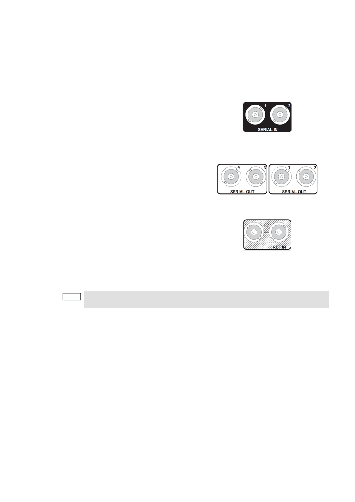
3.1 IQUDC3000-1A(B)3
3.1.1 SDI Inputs
Serial digital inputs to the module are made
via two BNC connectors which terminate in
75 Ohms.
3.1.2 SDI Outputs
Serial digital outputs from the module are
made via four BNC connectors which
terminate in 75 Ohms.
3.1.3 Reference Input
An external sync input to the module is made
via passive loop-through BNC connectors
which terminate in 75 Ohms.
Operation to full specification is only possible with a correctly terminated, noise-free, stable,
black sync reference input. While lock may be achieved with an unsuitable sync source, the
increased jitter evident on the SDI output will affect locking and cable length performance at
the receiving equipment.
If the loop-through facility is not used, the unused BNC socket must be fitted with a 75 Ohm
terminator.
Issue 1 Rev 4 Page 23 © 2016 SAM

IQUDC30/IQUDC31/IQUDC32/IQUDC33 Connections
3.2 IQUDC3001-1B3
3.2.1 SDI Inputs
Serial digital inputs to the module are made
via two BNC connectors which terminate in
75 Ohms.
3.2.2 SDI Outputs
Serial digital outputs from the module are
made via five BNC connectors which
terminate in 75 Ohms.
3.2.3 GPIO
General Purpose Interface (GPI) connection
is made via a 3-pin closing-contact screw
terminal connector.
Connections can be inputs or outputs.
3.3 IQUDC3002-1A(B)3
3.3.1 SDI Inputs
Serial digital inputs to the module are made
via two BNC connectors which terminate in
75 Ohms.
3.3.2 SDI Outputs
Serial digital outputs from the module are
made via three BNC connectors which
terminate in 75 Ohms.
3.3.3 Reference Input
External sync input to the module is made via
a BNC connector which terminates in 75
Ohms.
Issue 1 Rev 4 Page 24 © 2016 SAM

IQUDC30/IQUDC31/IQUDC32/IQUDC33 Connections
3.3.4 SFP
A dual SFP connector offers support for a
variety of SFP options (see page 12).
Two ports provide dual TX, dual RX, or a
TX/RX combination, dependent on the
module fitted.
3.4 IQUDC3003-1B3
3.4.1 SDI Inputs
Serial digital inputs to the module are made
via two BNC connectors which terminate in
75 Ohms.
3.4.2 SDI Outputs
Serial digital outputs from the module are
made via four BNC connectors which
terminate in 75 Ohms.
3.4.3 SFP
A dual SFP connector offers support for a
variety of SFP options (see page 12).
Two ports provide dual TX, dual RX, or a
TX/RX combination, dependent on the
module fitted.
3.5 IQUDC3100-1B3
3.5.1 SDI Inputs
Serial digital inputs to the module are made
via two BNC connectors which terminate in
75 Ohms.
3.5.2 SDI Outputs
Serial digital outputs from the module are
made via four BNC connectors which
terminate in 75 Ohms.
Issue 1 Rev 4 Page 25 © 2016 SAM

IQUDC30/IQUDC31/IQUDC32/IQUDC33 Connections
Note:
3.5.3 Reference Input
An external sync input to the module is made
via passive loop-through BNC connectors
which terminate in 75 Ohms.
Operation to full specification is only possible with a correctly terminated, noise-free, stable,
black sync reference input. While lock may be achieved with an unsuitable sync source, the
increased jitter evident on the SDI output will affect locking and cable length performance at
the receiving equipment.
If the loop-through facility is not used, the unused BNC socket must be fitted with a 75 Ohm
terminator.
Issue 1 Rev 4 Page 26 © 2016 SAM

IQUDC30/IQUDC31/IQUDC32/IQUDC33 Connections
3.6 IQUDC3101-1B3
3.6.1 SDI Inputs
Serial digital inputs to the module are made
via two BNC connectors which terminate in
75 Ohms.
3.6.2 SDI Outputs
Serial digital outputs from the module are
made via five BNC connectors which
terminate in 75 Ohms.
3.6.3 GPIO
General Purpose Interface (GPI) connection
is made via a 3-pin closing-contact screw
terminal connector.
Connections can be inputs or outputs.
3.7 IQUDC3102-1B3
3.7.1 SDI Inputs
Serial digital inputs to the module are made
via two BNC connectors which terminate in
75 Ohms.
3.7.2 SDI Outputs
Serial digital outputs from the module are
made via three BNC connectors which
terminate in 75 Ohms.
3.7.3 Reference Inputs
External sync input to the module is made via
a BNC connector which terminates in 75
Ohms.
Issue 1 Rev 4 Page 27 © 2016 SAM

IQUDC30/IQUDC31/IQUDC32/IQUDC33 Connections
3.7.4 SFP
A dual SFP connector offers support for a
variety of SFP options (see page 12).
Two ports provide dual TX, dual RX, or a
TX/RX combination, dependent on the
module fitted.
3.8 IQUDC3103-1B3
3.8.1 SDI Inputs
Serial digital inputs to the module are made
via two BNC connectors which terminate in
75 Ohms.
3.8.2 SDI Outputs
Serial digital outputs from the module are
made via four BNC connectors which
terminate in 75 Ohms.
3.8.3 SFP
A dual SFP connector offers support for a
variety of SFP options (see page 12).
Two ports provide dual TX, dual RX, or a
TX/RX combination, dependent on the
module fitted.
3.9 IQUDC3200-2A(B)3
3.9.1 SDI Inputs
Serial digital inputs to the module are made
via two BNC connectors which terminate in
75 Ohms.
3.9.2 SDI Outputs
Serial digital outputs from the module are
made via four BNC connectors which
terminate in 75 Ohms.
Issue 1 Rev 4 Page 28 © 2016 SAM

IQUDC30/IQUDC31/IQUDC32/IQUDC33 Connections
Note:
3.9.3 Reference Input
An external sync input to the module is made
via passive loop-through BNC connectors
which terminate in 75 Ohms.
Operation to full specification is only possible with a correctly terminated, noise-free, stable,
black sync reference input. While lock may be achieved with an unsuitable sync source, the
increased jitter evident on the SDI output will affect locking and cable length performance at
the receiving equipment.
If the loop-through facility is not used, the unused BNC socket must be fitted with a 75 Ohm
terminator.
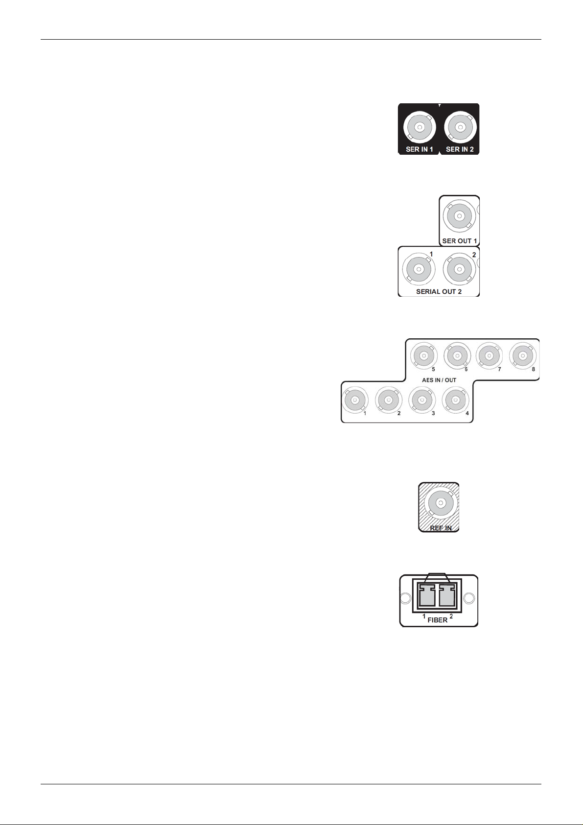
3.10 IQUDC3202-2A(B)3
3.10.1 SDI Inputs
Serial digital inputs to the module are made
via two BNC connectors which terminate in
75 Ohms.
3.10.2 SDI Outputs
Serial digital outputs from the module are
made via three BNC connectors which
terminate in 75 Ohms.
3.10.3 AES Inputs/Outputs
AES audio inputs/outputs to/from the module
are made via eight BNC connectors which
terminate in 75 Ohms.
3.10.4 Reference Input
External sync input to the module is made via
a BNC connector which terminates in 75
Ohms.
Issue 1 Rev 4 Page 29 © 2016 SAM

IQUDC30/IQUDC31/IQUDC32/IQUDC33 Connections
Note:
3.10.5 SFP
A dual SFP connector offers support for a
variety of SFP options (see page 12).
Two ports provide dual TX, dual RX, or a
TX/RX combination, dependent on the
module fitted.
3.11 IQUDC3203-2A(B)3
3.11.1 SDI Inputs
Serial digital inputs to the module are made
via two BNC connectors which terminate in
75 Ohms.
3.11.2 SDI Outputs
Serial digital outputs from the module are
made via four BNC connectors which
terminate in 75 Ohms.
3.11.3 GPIO
General Purpose Interface (GPI) connections
are made via a 3-pin closing-contact screw
terminal connector.
Connections can be inputs or outputs.
3.11.4 Reference Input
An external sync input to the module is made
via passive loop-through BNC connectors
which terminate in 75 Ohms.
Operation to full specification is only possible with a correctly terminated, noise-free, stable,
black sync reference input. While lock may be achieved with an unsuitable sync source, the
increased jitter evident on the SDI output will affect locking and cable length performance at
the receiving equipment.
If the loop-through facility is not used, the unused BNC socket must be fitted with a 75 Ohm
terminator.
Issue 1 Rev 4 Page 30 © 2016 SAM

IQUDC30/IQUDC31/IQUDC32/IQUDC33 Connections
3.11.5 SFP
A dual SFP connector offers support for a
variety of SFP options (see page 12).
Two ports provide dual TX, dual RX, or a
TX/RX combination, dependent on the
module fitted.
3.11.6 AES Inputs/Outputs
AES audio inputs/outputs to/from the module
are made via a 25-way D-type connector.
Where supported by the appropriate rear panel, AES connections are as follows:
25 Way D-Type Connector
Solder Pin Side
AES Audio I/O
Channel 25 Way D-Type Pin Channel 25 Way D-Type Pin
Chassis 1 GND5 20
GND1 14 Port 4+ 8
Port 8+ 2 Port 4- 21
Port 8- 15 Port 3+ 9
Port 7+ 3 Port 3- 22
Port 7- 16 GND6 10
GND2 4 GND7 23
GND3 17 Port 2+ 11
Port 6+ 5 Port 2- 24
Port 6- 18 Port 1+ 12
Port 5+ 6 Port 1- 25
Port 5- 19 GND8 13
GND4 7 - -
Issue 1 Rev 4 Page 31 © 2016 SAM

IQUDC30/IQUDC31/IQUDC32/IQUDC33 Connections
Note:
3.12 IQUDC3300-2A(B)3
3.12.1 SDI Inputs
Serial digital inputs to the module are made
via two BNC connectors which terminate in
75 Ohms.
3.12.2 SDI Outputs
Serial digital outputs from the module are
made via four BNC connectors which
terminate in 75 Ohms.
3.12.3 Reference Input
An external sync input to the module is made
via passive loop-through BNC connectors
which terminate in 75 Ohms.
Operation to full specification is only possible with a correctly terminated, noise-free, stable,
black sync reference input. While lock may be achieved with an unsuitable sync source, the
increased jitter evident on the SDI output will affect locking and cable length performance at
the receiving equipment.
If the loop-through facility is not used, the unused BNC socket must be fitted with a 75 Ohm
terminator.
Issue 1 Rev 4 Page 32 © 2016 SAM
IQUDC30/IQUDC31/IQUDC32/IQUDC33 Connections
3.13 IQUDC3302-2A(B)3
3.13.1 SDI Inputs
Serial digital inputs to the module are made
via two BNC connectors which terminate in
75 Ohms.
3.13.2 SDI Outputs
Serial digital outputs from the module are
made via three BNC connectors which
terminate in 75 Ohms.
3.13.3 AES Inputs/Outputs
AES audio inputs/outputs to/from the module
are made via eight BNC connectors which
terminate in 75 Ohms.
3.13.4 Reference Input
External sync input to the module is made via
a BNC connector which terminates in 75
Ohms.
3.13.5 SFP
A dual SFP connector offers support for a
variety of SFP options (see page 12).
Two ports provide dual TX, dual RX, or a
TX/RX combination, dependent on the
module fitted.
Issue 1 Rev 4 Page 33 © 2016 SAM

IQUDC30/IQUDC31/IQUDC32/IQUDC33 Connections
Note:
3.14 IQUDC3303-2A(B)3
3.14.1 SDI Inputs
Serial digital inputs to the module are made
via two BNC connectors which terminate in
75 Ohms.
3.14.2 SDI Outputs
Serial digital outputs from the module are
made via four BNC connectors which
terminate in 75 Ohms.
3.14.3 GPIO
General Purpose Interface (GPI) connections
are made via a 3-pin closing-contact screw
terminal connector.
Connections can be inputs or outputs.
3.14.4 Reference Input
An external sync input to the module is made
via passive loop-through BNC connectors
which terminate in 75 Ohms.
Operation to full specification is only possible with a correctly terminated, noise-free, stable,
black sync reference input. While lock may be achieved with an unsuitable sync source, the
increased jitter evident on the SDI output will affect locking and cable length performance at
the receiving equipment.
If the loop-through facility is not used, the unused BNC socket must be fitted with a 75 Ohm
terminator.
3.14.5 SFP
A dual SFP connector offers support for a
variety of SFP options (see page 12).
Two ports provide dual TX, dual RX, or a
TX/RX combination, dependent on the
module fitted.
Issue 1 Rev 4 Page 34 © 2016 SAM

IQUDC30/IQUDC31/IQUDC32/IQUDC33 Connections
3.14.6 AES Inputs/Outputs
AES audio inputs/outputs to/from the module
are made via a 25-way D-type connector.
Where supported by the appropriate rear panel, AES connections are as follows:
25 Way D-Type Connector
Solder Pin Side
AES Audio I/O
Channel 25 Way D-Type Pin Channel 25 Way D-Type Pin
Chassis 1 GND5 20
GND1 14 Port 4+ 8
Port 8+ 2 Port 4- 21
Port 8- 15 Port 3+ 9
Port 7+ 3 Port 3- 22
Port 7- 16 GND6 10
GND2 4 GND7 23
GND3 17 Port 2+ 11
Port 6+ 5 Port 2- 24
Port 6- 18 Port 1+ 12
Port 5+ 6 Port 1- 25
Port 5- 19 GND8 13
GND4 7 - -
Issue 1 Rev 4 Page 35 © 2016 SAM

IQUDC30/IQUDC31/IQUDC32/IQUDC33 Card Edge LEDs
4 Card Edge LEDs
The LEDs on the edge of the module indicate its operating status.
LED Color State Indication
+ PWR Green Illuminated A positive power supply is present.
- PWR G reen Illuminated A negative power supply is present.
CPU OK Green Flashing The CPU is running.
FPGA OK Green Flashing The FPGA is running.
IN A Green Illuminated A valid input is present on channel 1.
IN B Green Illuminated A valid input is present on channel 2.
REF Green Illuminated Genlock to selected reference OK.
Green Flashing Genlock to selected reference is crosslocked or
has a reference standard error.
ERR Red Illuminated The CPU is not running.
WARN Yellow Illuminated The channel 1 or channel 2 selected input is lost.
OK Green Illuminated The module is operating correctly.
Issue 1 Rev 4 Page 36 © 2016 SAM
IQUDC30/IQUDC31/IQUDC32/IQUDC33 Operation Using the RollCall Control Panel
Note:
Note:
5 Operation Using the RollCall Control Panel
The screens shown in this section are for guidance and reference only, and may be slightly
different to those on your unit.
5.1 Information Window
The Information Window is displayed at the top of each screen. When an option is selected in
the Information Window, the Unit Status area shows corresponding information about the
status of the module.
Processing channel 2 information is only applicable to the IQUDC31 and IQUDC33.
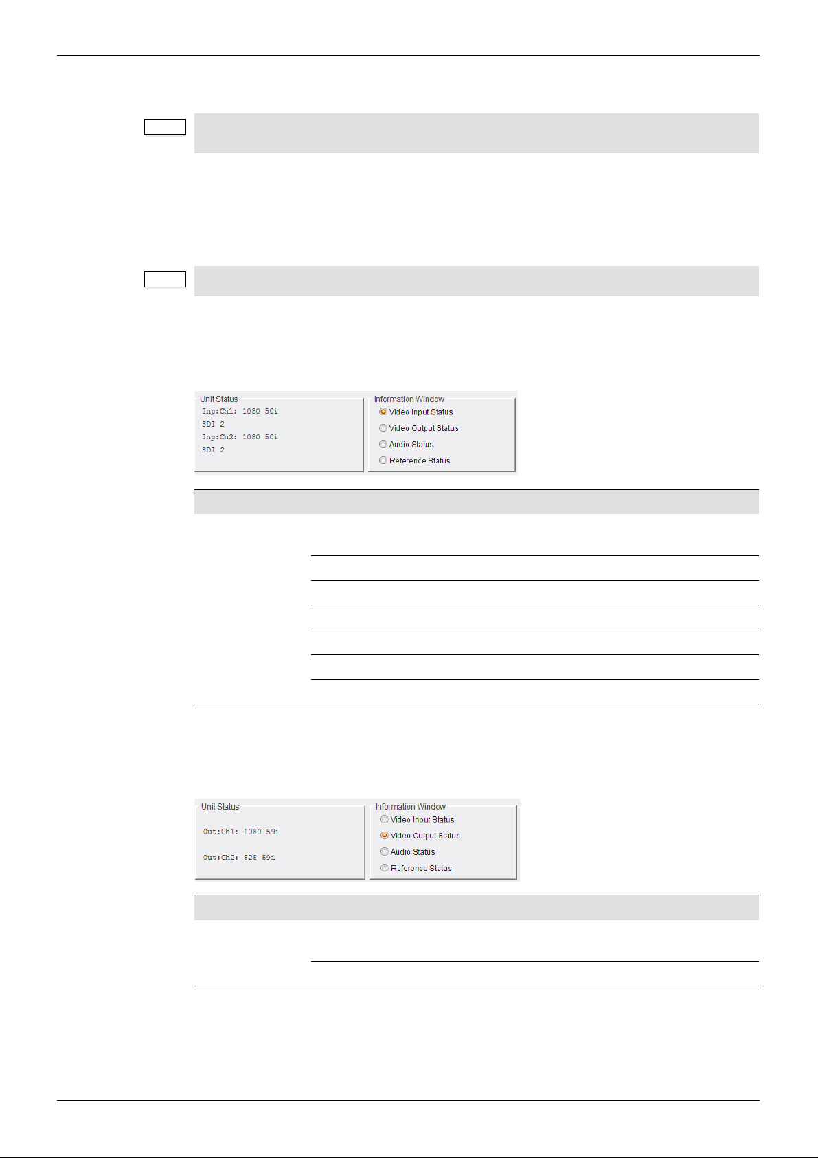
5.1.1 Video Input Status
When Video Input Status is selected in the Information Window, the Unit Status area shows
input status information for processing channels 1 and 2.
Information Status Description
Inp: Ch1:
Inp: Ch2:
1080 50p-A
(example)
Loss No input signal received.
SDI 1 Input source is SDI 1.
SDI 2 Input source is SDI 2.
CVBS Input source is CVBS.
SFP 1 Input source is SFP 1.
SFP 2 Input source is SFP 2.
5.1.2 Video Output Status
When Video Output is selected in th e Info rma tio n Win dow, the Unit Status area shows output
status information for processing channels 1 and 2.
Shows the current detected input video standard . F or
a list of supported standards, see page 18.
Information Status Description
Out: Ch1:
Out: Ch2:
Issue 1 Rev 4 Page 37 © 2016 SAM
625 50i
(example)
Loss No output signal.
Shows the current output video standard. For a list of
supported standards, see page 18.
IQUDC30/IQUDC31/IQUDC32/IQUDC33 Operation Using the RollCall Control Panel
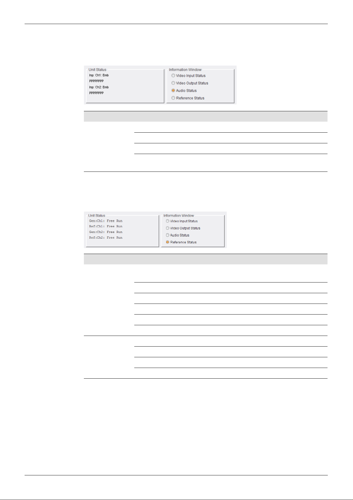
5.1.3 Audio Status
When Audio Status is selected in the Information Window, the Unit Status area shows
embedded audio input status information for processing channels 1 and 2.
Information Status Description
Inp: Ch1: Emb
Inp: Ch2: Emb
5.1.4 Reference Status
When Reference Status is selected in the Information Window, the Unit Status area shows
genlock and reference status information for pro ces sin g ch an ne ls 1 an d 2.
Information Status Description
Gen:Ch1:
Gen:Ch2:
L No audio signal received.
P Audio input is PCM.
D Audio input is data or Dolby E (non-PCM).
Note: The number of status letters shown denotes the number of audio
pairs. For example, eight status letters = eight audio pairs.
Mod Ref Output video locked to the inc omi n g re ar -panel
reference.
Chs Ref A Output video locked to incoming chassis reference A.
Chs Ref B Output video locked to incoming chassis reference B.
Ch1 Input Output video locked to channel 1 input.
Ch 2 Input Output video locked to channel 2 input.
Free Run Output video locked to an internal reference clock.
Ref:Ch1:
Ref: Ch2:
Loss No reference present.
Genlock Locked to reference.
Clocklock Cross-locked to reference.
Free Run Free-running.
Issue 1 Rev 4 Page 38 © 2016 SAM

IQUDC30/IQUDC31/IQUDC32/IQUDC33 Operation Using the RollCall Control Panel
Note:
Note:
5.2 Input
The Input screen enables you to select a video input source for each processing channel.
The Input Source Ch 2 controls are only applicable to the IQUDC31 and IQUDC33.
5.2.1 Input Source Ch 1 and Ch 2
Input Source Ch 1 and Ch 2 list s the available vi deo input sources. A choice of the fo llowing is
available, depending on the rear panel fitted:
• SDI 1–2: Always present. Enables the selection of serial input 1 or serial input 2
respectively.
• SFP 1–2: The Small Form-factor Pluggable (SFP) inputs are only available to
products with an SFP connector rear panel. If the rear panel has no SFP connector,
the input option is hidden.
The SFP input selections will appear grayed out if either no SFP module or an
unsupported SFP module is inserted in the rear panel connector.
• Current Input Standard: Shows the video standard of the input source selected.
The unit automatically detects the input standard.
Issue 1 Rev 4 Page 39 © 2016 SAM

IQUDC30/IQUDC31/IQUDC32/IQUDC33 Operation Using the RollCall Control Panel
Note:
5.3 Output-Ch1 and Ch2
The Output-Ch1 and Ch2 screens enable you to apply various settings and adjustments to
the video output signal for each video processing channel.
• The Output-Ch2 screen and SFP Output Routing selection control are only
applicable to the IQUDC31 and IQUDC33.
• The screen shot above shows the Output Standards available when the Linear
Frame Rate converter option is fitted. When not fitted, only same frame rate
(i.e. format) conversions are permitted.
• Low frame rate support (i.e. 23, 24, 25, 29 Hz) is not available in modules which
were upgraded to V5.2.7 or above after installation. Only new builds of modules at
version 5.2.7 and above will support low frame rate signals.
5.3.1 Output Standard
• Format: Selects the output format.
• Default Field Rate: Selects the output field/frame rate from a choice of Last Valid
Input, 50 Hz, and 60 Hz. This control only has an effect when the channel’s selected
video input is not detected.
Note: The output video field/frame rate will be the same as the selected input to the
channel. If the input is not detected, default field rate allows user control of output
field/frame rate.
• Current Output Standard: Shows the output standard currently in use.
Issue 1 Rev 4 Page 40 © 2016 SAM

IQUDC30/IQUDC31/IQUDC32/IQUDC33 Operation Using the RollCall Control Panel
Note:
5.3.2 Default Output
On input signal loss, select
• Black to set default output to black (default)
• Pattern to set default output to the last chosen test pattern
• Freeze to freeze the screen at the last frame received before signal loss.
If the last chosen test pattern was black, then if default output is chosen to be “Pattern”, the
output will go to black on input loss.
5.3.3 Scrolling Caption Generator
The Scrolling Caption Generator overlays a black text box with a user-defined caption onto
the output video. This is generally used as a setup or debug tool to help identify a video
stream on a monitor.
• Caption Entry: User-defined caption. To enter a caption:
• Caption Scroll: Enables slow-speed horizontal scrolling of the caption within the
• Caption Enable: The master enable – turns the caption display on and off.
5.3.4 Freeze
The Force Freeze check box enables to freeze the output picture.
In the Caption Entry field, enter the required text and click S to set. To return to the
preset value, click P (“Channel 1” is the preset caption).
Note: Text can be no more than 19 characters.
black text box. Scrolling is from right to left, and wraps around for continuous display.
Issue 1 Rev 4 Page 41 © 2016 SAM

IQUDC30/IQUDC31/IQUDC32/IQUDC33 Operation Using the RollCall Control Panel
Note:
5.3.5 Legalization
Legalizer ensures that the output video stays within the legal RGB gamut limit, making it
suitable for the broadcast signal chain. To achieve this, the Legalizer reduces the gain equally
on all channels.
The level the legalizer scales down to is selected using the radio buttons in RollCall. Anything
in the RGB space above the selected level is scaled down to that level. Anything in the RGB
space below 0 mV is clipped to 0 mV. This is a good compromise between minimizing hue
change and raising apparent brightness.
Legalizer choices are:
• Off (Default)
•700mV
•721mV
•735mV
•746mV
5.3.6 SFP Output Routing
In a dual-channel product that has SFP TX connectors, the source of the SFP output can be
either channel 1 or channel 2. The SFP outputs are only available in products variants that
have an SFP connector rear panel. If the rear panel has no SFP connector, the output option
is hidden.
The SFP input selections will appear grayed out if either no SFP module or an unsupported
SFP module is inserted in the rear panel connector.
• SFP Source 1 and 2: Selects the source, either channel 1 or channel 2, for SFP 1
and SFP 2 if they are transmit ports.
Note: SFP Source 1 and 2 can be set from either the Output-Ch1 or Output-Ch2
screen – any change in one screen is reflected in the other. See page 40.
5.3.7 Test Patterns
The Test Patterns list enables you to choose the type of pattern displayed on the output
picture. You can choose from Off, Black, Ramp, and Bars.
Issue 1 Rev 4 Page 42 © 2016 SAM

IQUDC30/IQUDC31/IQUDC32/IQUDC33 Operation Using the RollCall Control Panel
5.3.8 Blanking
• Embedded Audio: Enables audio embedding in the output video. This control does
not affect any other horizontal data.
• SD Half Line: Blanks the source half lines. This can be useful for certain ARC
settings, for example, SD16:9AN to SD4:3 Fit to Width.
5.3.9 Luma Clipper
When enabled, the Luma Clipper applies a hard clip to white maximum and black minimum
levels.
• White Max: Hard clip maximum white. The adjustment range is 90% to 109% in 1%
steps.
• Black Min: Hard clip minimum black. The adjustment range is -7% to 10% in 1%
steps.
Issue 1 Rev 4 Page 43 © 2016 SAM

IQUDC30/IQUDC31/IQUDC32/IQUDC33 Operation Using the RollCall Control Panel
Note:
Note:
5.3.10 Logo Control (Option)
When the optional logo inserter is installed, additional controls are available.
When using the logo insertion feature with input and output signals of the same frame rate
and format, ensure that Sync Mode (see section 5.6.1) is enabled to preserve output
quality.
• Logo control - Lists the available logos that have been uploaded to the unit via the
separate logo installation application (see Appendix 2). The currently selected logo is
highlighted.
• Load: Click Load to load the selected logo.
• Take - Displays the logo.
• H position - H position determines the horizontal pl acement of the logo from 0% (left
edge of picture) to 100% (the logo's furthest edge is on the picture right edge), in
steps of 1%.
Preset is 10%.
• V position - V position determines the vertical placement of the logo from 0% (top of
picture) to 100% (the logo's bottom edge is on the picture bottom edge), in steps of
1%.
Preset is 10%.
• Transparency - Transparency allows you to adjust the visibility of the logo from 0%
(fully visible) to 100% (invisible) in steps of 1%.
Preset is 10%.
• Pre-shaped - Indicates if the logo is pre-shaped (see Appendix 2)
• Delete - Deletes the highlighted logo.
For a logo to be deleted, it must first have been loaded.
• State - Indicates if a logo has been loaded and is ready for display.
• Logo selected - Indicates the name of the logo currently being displayed.
Issue 1 Rev 4 Page 44 © 2016 SAM

IQUDC30/IQUDC31/IQUDC32/IQUDC33 Operation Using the RollCall Control Panel
Note:
• For more details about the Logo insertion option, including information about how
logos are uploaded to the module, see Appendix 2
• Loading the logo ready for display can take up to a few minutes depending on the
logo length. Short or static logos will only take a few seconds. The logo displayed
state will report progress in loading the logo.
Logo insertion worked example:
1. To insert a new logo, select the logo from the list under Logo Control, click the Load
button, then enable the logo by clicking in the Take box.
2. To change the logo, select the required logo from the list, then click the Load button.
This will display the new logo.
3. To remove a logo from display, uncheck the Take box.
4. To display the logo shown in the Logo Selected box, click in the Take box.
Issue 1 Rev 4 Page 45 © 2016 SAM

IQUDC30/IQUDC31/IQUDC32/IQUDC33 Operation Using the RollCall Control Panel
Note:
5.4 Video-Ch1 and Ch2
The Video-Ch1 and Ch2 screens enable you to apply various types of signal processing to
the signal being converted, and includes Proc Amp, Nonlinear Enhancer, Conversion
Apertures, and Noise Reduction (option) controls.
The Video-Ch2 screen is only applicable to the IQUDC31 and IQUDC33.
5.4.1 Proc Amp
The Process Amplifier (Proc Amp) enables you to correct video inconsistencies, such as
contrast.
• Enable: Enables the Proc Amp.
• Master gain: Adjusts contrast and saturation together from -6 dB to 6 dB in 0.2 dB
steps. The preset value is 0 dB.
• Contrast: Adjusts the contrast. The adjustment range is -6 dB to 6 dB in 0.2 dB steps.
The preset value is 0 dB.
• Saturation: Adjusts the color saturation. The adjustment range is -6 dB to 6 dB in
0.2 dB steps. The preset value is 0 dB.
• Black Level: Adjusts the black level. The adjustment range is -100 mV to 100 mV.
The preset value is 0 mV.
Issue 1 Rev 4 Page 46 © 2016 SAM

IQUDC30/IQUDC31/IQUDC32/IQUDC33 Operation Using the RollCall Control Panel
• Gamma: Adjusts the gamma curve. The adjustment range is 0.4 to 1. 7 in 0.1 ste ps.
The preset value is 1.0.
• YC Offset: Adjusts the horizontal chroma shift, for use when correcting upstream
luma-chroma displacement. The adjustment range is -20 to 20 in steps of 2 luma
clocks.
At the input picture edge, zero chroma is shifted into the active picture area. If the
ARC is set to show less than the full width of the input picture, valid input picture
chroma is shifted into the output picture area.
5.4.2 Nonlinear Enhancer
The Nonlinear Enhancer defines the amount of enhancement applied to a video to help
regain lost detail. This could be as a result of degraded material, post production processes,
or because the initial capture conditions were not ideal.
The controls enable you to apply enhancement to the low, medium, and high frequency
bands, and to create a custom setting if required.
• Enable: Enables the enhancer.
• Mode: Preset controls.
• Low: Sets Level to 2 and Noise Rejection to 15% for the selected frequency
band.
• Medium: Sets Level to 4 and Noise Rejection to 15% for the selected frequency
band.
• High: Sets Level to 6 and Noise Rejection to 15% for the selected frequency
band.
• Super: Sets Level to 8 and Noise Rejection to 15% for the selected frequency
band.
• Manual: Enables you to manually adjust the Gain and Noise Rejection.
• Frequency Band: S pecifies th e frequency band to which the enhan cement is app lied.
• Level: Adjusts the enhancement level. The adjustment range is 0 to 192. The preset
value is 0.
• Noise Rejection: Adjusts the Gain and Noise Rejection. The adj ustment range is 0 to
100 in steps of 1. The preset value is 0.
Issue 1 Rev 4 Page 47 © 2016 SAM

IQUDC30/IQUDC31/IQUDC32/IQUDC33 Operation Using the RollCall Control Panel
5.4.3 Conversion Aperture
The Conversion Aperture controls enable you to control the horizontal and vertical rescaler
apertures from a range of presets.
5.4.3.1 Preset
Preset returns all settings to their default values.
5.4.3.2 Vertical
Vertical controls aliasing in down-converted content.
• Level: Specifies the enhancer strength.
• Soft 1–2: Provides attenuation in the frequency band specified.
• Normal: Nominally flat frequency response.
• Sharp 1–2: Applies more boost in the frequency band specified.
• Frequency Band: S pecifies th e frequency band to which the enhan cement is app lied.
5.4.3.3 Horizontal
Horizontal controls aliasing in down-converted content
• Sharpness: Determines the sharpness of the outp ut by changing the ra te of anti-alias
filter cut-off.
• Soft 2: Recommended for severely over enhanced source material.
• Soft 1: Recommended for over enhanced source material.
• Normal: Optimum setting for balancing detail and alias.
• Sharp1: Recommended for slightly soft source material.
• Sharp 2: Recommended for very soft source material.
• Detail: Determines the amount of detail allowed through to the output by moving the
anti-alias filter stop band.
• Low 2: Recommended for severely over enhanced source material.
• Low 1: Recommended for over enhanced source material.
• Normal: Optimum setting for balancing detail and alias.
• High 1: Recommended for slightly soft source material.
• High 2: Recommended for very soft source material.
5.4.4 Noise Reduction (Option)
The Noise Reduction controls enable you to reduce levels of noise and grain.
• Enable: Master enable for all the noise reduction processing.
• Split Screen: Displays a split screen view of the output image – one side of the
screen shows the image with noise reduction, and the other side of the screen shows
the image without noise reduction.
Issue 1 Rev 4 Page 48 © 2016 SAM

IQUDC30/IQUDC31/IQUDC32/IQUDC33 Operation Using the RollCall Control Panel
5.4.4.1 Recursive
To achieve noise reduction, the recursive filter applies a temporal recursive filter to both
luminance and chrominance picture content. To avoid blurring moving objects, the filter
includes motion detection and adaption which disables the filter when significant motion is
present.
The Luma and Chroma controls set the maximum noise reduction (0 = off). You can set the
sensitivity of motion detection either automatically with Auto mode, or manually with the
Threshold slider.
• Luma: Adjusts the amount of noise reduction applied to the luminance signal. The
adjustment range is 0 to 7 in steps of 1. The preset value is 0.
• Chroma: Adjusts the amount of noise reduction applied to the chrominance signal.
The adjustment range is 0 to 7 in steps of 1. The preset value is 0.
• Threshold: Adjusts the noise reduction threshold. The adjustment range is 0 to 7 in
steps of 1. The preset value is 0.
• Mode: Choose between automatic or manual filtering.
In Auto mode, the background noise level is mea sured and the thresh old set to give a
good compromise between noise reduction and motion blur. In Manual mode,
increasing the Threshold value allows for pictures with higher background noise.
5.4.4.2 Spatial
The spatial noise reduction filter operates on luminance only and uses nearby samples to
average out noise. Picture objects and edges are detected and the filtering disabled.
Y o u can set the sensitivity of edge detectio n either automatically with Auto mode, or ma nually
with the Threshold slider.
• Level: Adjusts the level of noise reduction applied to the signal. The adjustment range
• Threshold: The adjustment range is 1 to 4 in steps of 1. The preset value is 1.
• Mode: Choose between automatic and manual filtering.
Note: For best results in Manual mode, always set the threshold to the lowest value
for the desired noise reduction.
is 0 to 7 in steps of 1. The preset value is 0.
In Auto mode, the background noise level is mea sured and the thresh old set to give a
good compromise between noise reduction and picture softness. In Manual mode,
increasing the Threshold value allows for pictures with higher background noise.
Note: For best results in Manual mode, always set the threshold to the lowest value
for the desired noise reduction.
Issue 1 Rev 4 Page 49 © 2016 SAM

IQUDC30/IQUDC31/IQUDC32/IQUDC33 Operation Using the RollCall Control Panel
Note:
5.5 Convert-Ch1 and Ch2
The Convert-Ch1 and Ch2 screens enable control of motion processing and improve the
conversion performance of stationary content.
l
The Convert-Ch2 screen is only applicable to the IQUDC31 and IQUDC33.
5.5.1 Up Conversion
• Clean Edge Upconversion: Enables the Texture Adaptive Upconversion (TAU)
process which helps to adapt away any horizontal ringing (vertica l edges).
5.5.2 Motion Processing
• Still Process: Uses powerful motion detection techniques to extract the maximum
resolution from interlaced sources while format or standards co nverting (where fitted).
The benefits of this processing are prominent on sta tic logos and computer-generated
overlays.
• Enhanced Still: Adds field motion detection to still processing. This reduces artifacts
on moving repetitive patterns.
• Enhanced Film Model: Applies an aperture with full progressive frequency re spon se
where the input is film transported by an interlaced video rate input, with cadence
enabled (see section 5.5.3).
• Enhanced De-interlace: Replaces missing lines with a gradient between the
previous and following lines. This control improves the appearance of de-interlaced
images and is useful when dealing with complex shapes.
• Clean Cut: Prevents temporal filtering across a cut in scenes, which can result in
several frames either side of the cut being a mix of the two different scenes.
Issue 1 Rev 4 Page 50 © 2016 SAM

IQUDC30/IQUDC31/IQUDC32/IQUDC33 Operation Using the RollCall Control Panel
Note:
5.5.3 Enhanced Film Mode
The Enhanced Film Mode provides a set of solutions to enable optimized conversion of film
originated content. Film originated content may be transported by standards supporting the
original film frame rate, such as 1080 23.98p. Film originated content may also be packed into
interlaced standards using a rule based method to map source frames to interlaced fields. In
this case, the interlaced standard's content is described as having a film cadence.
In order to perform high quality conversion of film originated content, the cadence must be
identified and used to adapt the interpolation process. The Enhanced Film Mode also pe rmit s
the synthesis of film cadence in the output.
The Enhanced Film Mode features include:
• Applying a 2:3 cadence when converting 23.94 psf to 59.94Hz.
• 2:3 detection and removal when converting 59.94 2:3 to 23.98 psf.
• Maintain 2:3 cadence when up-converting 59.94 2:3 content.
• Maintain 2:3 cadence when down-converting 59.94 2:3 content.
• Maintain psf cadence when appropriate.
• Control 2:3 cadence with respect to timecode.
The “Enhanced Film Mode” sets a sharp conversion aperture suited to filmic content. Select
“on” under the Enhanced Film Mode menu option (default is off). For content that is not
exclusively filmic, or where there are inconsistencies with the input cadence, this mode may
create higher visibility of artifacts.
This mode is only relevant for film originated content where the cadence is carried in an
interlaced format. In circumstances where the film originated content is carried in a
progressive format, the “Enhanced Film Mode” setting should not be used.
5.5.4 Input Cadence
Input Cadence controls allow you to define any cadence associated with the input video.
• Film Cadence - Enable if the input content is film originated, or simulates film
originated content. Default = Off.
• 59 Cadence - If the input is film originated and its frame rate is 59.94Hz, then the
cadence should be defined as either
• 2:3 (Default)
• 2:2 (psf)
• 2:3 Source
• When set to Automatic (Default) the input cadence will be determined by the
cadence detection circuit. This feature is useful when the source material
contains mixed cadences.
• When set to Input Timecode, the user defines the relationship between
timecode and the 2:3 sequence. This feature is useful when the source material
contains known continuous 2:3. This setting removes any uncert ainty that may be
associated by use of the sequence detector (automatic mode).
• 2:3 Start Hour - This control allows the user to define the position of timecode when
the 2:3 sequence begins. The assumption is mad e th at th e start of the 2: 3 seq u en ce
is aligned with the start of program and under norm al working practices, that the start
of program is coincident with a integer hour value.
This control is only active when “2:3 Source” is set to Input Timecode. Control is
available from 1 hour to 23 hours in steps of 1 hour. Default is 1 hour.
Issue 1 Rev 4 Page 51 © 2016 SAM

IQUDC30/IQUDC31/IQUDC32/IQUDC33 Operation Using the RollCall Control Panel
Note:
5.5.5 Output Cadence
The Output Cadence controls enable yo u to defi ne the required cadence of the output video.
• Film Cadence - Enable if the output content is required to have a film cadence
associated with it. Default = Off
• 59 Cadence - If the output is to have a film cadence associated with it an d its frame
rate is 59.94Hz, then the cadence should be defined as either
• 2:3 (Default)
• 2:2 (psf)
• 2:3 Source - In circumstances where the output is defined as 59.94 2:3, this control
allows the user to decide if they wish to control the starting point of the 2:3 sequence
with respect to timecode.
• When set to Free Run (Default) the output 2:3 cadence starting point is not
defined. The output will have continuous 2:3, but may vary from conversion to
conversion.
• When set to Output Timecode, the user defines the point where the 2:3
sequence starts relative to timecode.
• 2:3 Start Hour - This control allows the user to define the starting position of the 2:3
sequence with respect to timecode. It is only active when 2:3 Source is set to Output
Timecode.
Control is available from 1 hour to 23 hours in steps of 1 hour. Default is 1 hour.
Cadence support is only available to modules released at V5.2.7 and above. Earlier
modules which were upgraded to V5.2.7 after installation will not support cadence control.
Issue 1 Rev 4 Page 52 © 2016 SAM
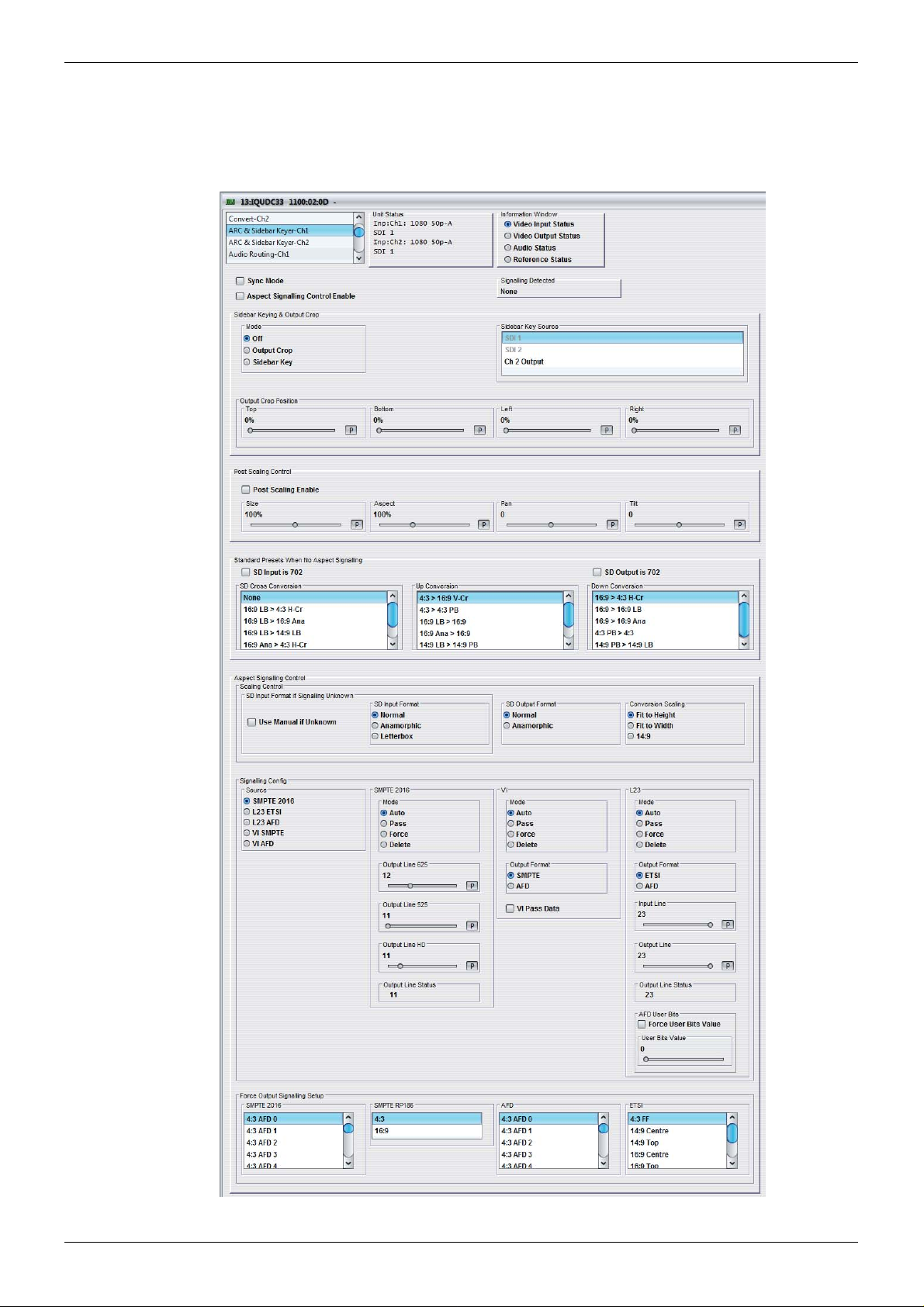
IQUDC30/IQUDC31/IQUDC32/IQUDC33 Operation Using the RollCall Control Panel
5.6 ARC & Sidebar Keyer-Ch1 and Ch2
The Aspect Ratio Control (ARC) & Sidebar Keyer-Ch1 a nd Ch2 screens enable you to contr ol
the aspect ratio of a picture from a range of options, or to adjust the size and position of the
picture manually.
Issue 1 Rev 4 Page 53 © 2016 SAM

IQUDC30/IQUDC31/IQUDC32/IQUDC33 Operation Using the RollCall Control Panel
Note:
5.6.1 Sync Mode
The Sync Mode check box disables the ARC feature when input and output formats are the
same. This gives the lowest latency and the best performance.
5.6.2 Aspect Signaling Control Enable
The Aspect Signaling Control Enable check box enables aspect signaling.
5.6.3 Signaling Detected
Signaling Detected shows the status of any aspect ratio signaling detected at the input. If
Status shows “None”, no valid signaling is detected.
5.6.4 Sidebar Keying & Output Crop (Option)
The Sidebar Keying & Output Crop functionality provides post ARC cropping of the output
picture and allows a second video picture to be keyed into the cropped area. When output
cropping is enabled, the actual size of the output picture does not change, just how much of
the active picture remains visible. The portion that is “cropped” is either default black (in
Output Crop mode) or is replaced by a secondary video picture (in Sidebar Key mode) – the
“cropped” portion still forms part of the output picture.
Output Crop is always available but Sidebar Key is a licensed option.
5.6.4.1 Mode
• Off: Disables both Output Crop and Sidebar Keying.
• Output Crop: Crops the output picture. In this mode the cropped area is black by
default. The cropped area is defined using the Output Cro p Position controls. See see
section 5.6.4.2 below.
• Sidebar Key: Keys a second video picture into the cropped area, as defined using
the Output Crop Position controls (see see section 5.6.4 .2 below). When selected, the
source of the second video picture is becomes available in the Sidebar Key Source
menu. See page 55.
5.6.4.2 Output Crop Position
The Output Crop position controls enable you to adjust which portion of the video picture is
visible by applying a border around the outside of the picture. The controls do not alter the
output active picture size – each control separately defines a percentage of the picture to be
replaced by a border . In Output Cro p mode, the border is d efault black. In Sidebar Key mo de,
the border is the “key” area replaced by the secondary Sidebar Key video source.
Controls are paired: top with bottom and left with right. A pair of controls has limitations to
prevent an overlap. The rule is that only 99% o f the picture can be cropped, either horizon tally
or vertically. For example, if Top is set to 50%, Bottom cannot exceed 49%.
• Top: Crops the output picture, from the top-edge down. The adjustment range is 0%
to 99% in 1% steps (0%). The default is 0%.
• Bottom: Crops the output picture, from the bottom-e dge up . The ad justment r an ge is
0% to 99% in 1% steps. The default is 0%.
• Left: Crops the ou tput picture, from the lef t-edge right. The adjustment ra nge is 0% to
99% in 1% steps. The default is 0%.
• Right: Crops the output picture, from the right-edge left. The adjustmen t range is 0%
to 99% in 1% steps. The default is 0%.
Issue 1 Rev 4 Page 54 © 2016 SAM

IQUDC30/IQUDC31/IQUDC32/IQUDC33 Operation Using the RollCall Control Panel
Note:
5.6.4.3 Sidebar Key Source
If the sidebar key option is available, the Sidebar Key Source control will also be present. This
control becomes active when Sidebar Key mode is selected. Firstly a border is set up around
the active picture using the separate Output Crop Position controls. This control then selects
the secondary video source to be keyed over the border area.
In order for this to work correctly, the following rules must be met:
• Sidebar Key Source must be of the same format and frame rate to the output video
standard for this channel.
• If the key source selected is of a d if f erent standard to the main video outp ut st andar d,
only Output Crop Mode is available.
• Ensure the key source has the correct vertical genlock alignment. If not, the sidebar
key will not have the correct vertical position.
The available sidebar key sources vary depending on the product variant:
• Single-channel product: all video inputs are available .
• Dual-channel product: all video inputs plus output from other channel are available.
All video inputs is Serial SDI, CVBS, and SFP.
Sidebar Key Source options that are not available to the product are hidd en from the selection
list (for example, the output of the second channel in a single-channel product, or SFP input if
no SFP rear is fitted).
Sidebar Key Source options that are not suitable are grayed out from the selection list (for
example, the source is the not the same output standard as the video it is being “keyed” into,
or SFP 2 is actually a TX so is not available as an input.
5.6.5 Post Scaling Control
Post Scaling Control enables you to manually adjust the size and position of the output
picture, post ARC scaling. This is an additional level of control which does not affect the ARC.
• Post Scaling Enable: Enables the Post Scaling controls.
• Size: Adjusts the size of the whole output image while maintaining aspe ct ratio. The
adjustment range is 80% to 120% in 1% steps. The preset value is 100%.
• Aspect: Adjusts the aspect ratio of the output image. The adjustment ran ge is 70% to
150% in 1% steps. The preset value is 100%.
• Pan: Adjusts the horizontal position of the output image. Range is from -50 to
50 pixels in steps of 1 pixel. Preset = 0
• Tilt: Adjusts the vertical position of the output ima ge. Range is -5 0 to 50 lines in ste ps
of 1 line. Preset = 0
Issue 1 Rev 4 Page 55 © 2016 SAM

IQUDC30/IQUDC31/IQUDC32/IQUDC33 Operation Using the RollCall Control Panel
Note:
Note:
Note:
5.6.6 Standard Presets When No Aspect Signaling
If no input aspect signaling is available and the conversion required is always from a known
input aspect ratio to another known input aspect ratio, one of the standard presets may be
selected. The presets are sub-divided into SD to SD cross conversion, SD to HD/3G up
conversion, and HD/3G to SD down conversion.
These presets are only active when the Aspect Signaling Control Enable check box is
deselected.
5.6.6.1 SD Input is 702
SD Input is 702 is an additional ARC preset mode, which is available for incoming content
that uses a 702 sample line rather than a 720 sample line. If the incoming content uses a 702
sample line, select the check box. This introduces an additional H scaling factor of 720/702,
resulting in a slight horizontal stretch.
This control only has an effect on SD inputs.
SD Input 702 introduces an additional h scaling factor of 720/702.
5.6.6.2 SD Output is 702
SD Output is 702 is an additional ARC preset mode, which is available for outgoing content
that requires a 702 sample line rather than a 720 sample line. If the outgoing content requires
a 702 sample line, select the check box. This introduces an additional H scaling factor of
702/720, resulting in a slight horizontal squeeze.
This control only has an effect on SD outputs.
SD Output 702 introduces an additional h scaling factor of 702/720.
5.6.6.3 SD Cross Conversion
LB = letterbox, h-crop = horizontal crop, ana = anamorphic.
Issue 1 Rev 4 Page 56 © 2016 SAM
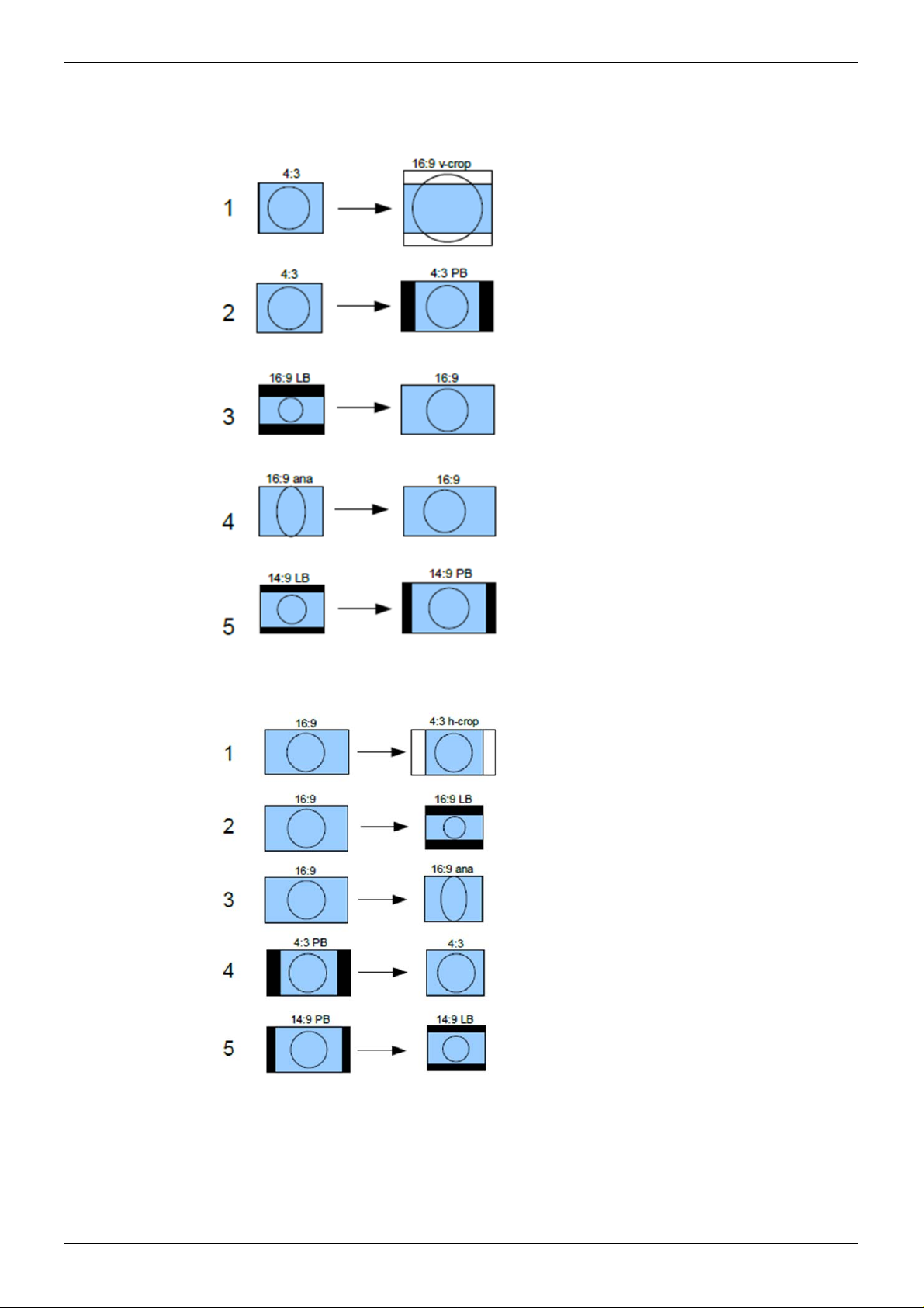
IQUDC30/IQUDC31/IQUDC32/IQUDC33 Operation Using the RollCall Control Panel
5.6.6.4 Up Conversion
LB = letterbox, PB = pillarbox, v-crop = vertical crop, ana = anamorphic.
5.6.6.5 Down Conversion
LB = letterbox, PB = pillarbox, h-crop = horizontal crop, ana = anamorphic.
Issue 1 Rev 4 Page 57 © 2016 SAM

IQUDC30/IQUDC31/IQUDC32/IQUDC33 Operation Using the RollCall Control Panel
5.6.7 Aspect Signaling Control – Scaling Control
The Scaling Control functions enable you to configure the ARC output format. The controls
are only active when using input aspect signaling to control the ARC input format. Using input
aspect signaling allows dynamic control of the ARC. A fixed aspect is selected for the output
image, and the aspect signaling then defines the incoming image aspect ratio. As this signal
changes on frame boundaries, the ARC is reconfigured to perform the correct conversion.
5.6.7.1 SD Input Format if Signaling Unknown
When using input aspect signaling with an SD input source, it is possible to set a default input
ARC setting. If, for any reason, the input SD aspect signaling cannot be detected, the ARC
assumes this default setting.
• Use Manual if Unknown: Enables manual ARC control.
• SD Input Format: The SD input format.
• Normal: Default 4:3 aspect ratio.
• Anamorphic: Horizontally squeezes a widescreen image to fit a standard 4:3
aspect ratio.
• Letterbox: Preserves the original aspect ratio of film shot in a widescreen aspect
ratio, with bars visible at the top and bottom of the screen.
5.6.7.2 SD Output Format
When Aspect Signaling Control is enabled and the output video is SD, this control enables
you to set fixed output aspects for the ARC.
• Normal: Default aspect ratio.
• Anamorphic: Horizontally squeezes a widescreen image to fit a standard 4:3 aspect
ratio.
5.6.7.3 Conversion Scaling
Conversion Scaling enables you to set fixed ARC output aspects.
• Fit to Height: Scales the image to fit the height of the screen while maintaining the
aspect ratio.
• Fit to Width: Scales the image to fit the width of the screen while maintaining the
aspect ratio.
• 14:9: Can scale either a 4:3 image for viewing on a 16:9 screen, or a 16:9 image for
viewing on a 4:3 screen. This is a compromise in order to maintain the aspect ratio of
the image, but will crop some of the image in the process (top and bottom when
viewing 16:9 and left and right when viewing 4:3).
See see section 5.6.8 for a list of possible ARC conversions using input signaling and a
combination of SD Output Format and Scaling Conversion controls.
Issue 1 Rev 4 Page 58 © 2016 SAM

IQUDC30/IQUDC31/IQUDC32/IQUDC33 Operation Using the RollCall Control Panel
5.6.8 Input Signaling ARC Conversions
It is possible to manually fix the output aspect of the ARC when using input signaling. The
input to the ARC is then defined by the dynamic input signaling.
The following sections show the ARC conversions possible using input signaling and a
combination of SD Output Format and Scaling Conversion controls. For each of the
conversions there are four columns of images. The first column shows the source image in
various formats, with each format described in the accomp anyin g input signal. The next three
columns show the output image format when the Fit to Width, 14:9, or Fit to Height
Conversion Scaling controls are selected.
5.6.8.1 SD Cross Conversion
SD Output Format = Normal (4:3).
SD Output Format = Anamorphic (16:9).
Issue 1 Rev 4 Page 59 © 2016 SAM

IQUDC30/IQUDC31/IQUDC32/IQUDC33 Operation Using the RollCall Control Panel
5.6.8.2 Up Conversion
SD Output Format has no effect as output is HD.
5.6.8.3 Down Conversion
SD Output Format = Normal (4:3).
SD Output Format = Anamorphic (16:9).
Issue 1 Rev 4 Page 60 © 2016 SAM

IQUDC30/IQUDC31/IQUDC32/IQUDC33 Operation Using the RollCall Control Panel
Note:
5.6.9 Aspect Signaling Control – Signaling Config
The Aspect Signaling Control functions define which of the supported aspect signaling
standards defines the input of the ARC.
5.6.9.1 Source
The Source box lists the available supported aspect signaling standa rds.
• SMPTE 2016: SMPTE ST 2016-1. Format for Active Format Description (AFD) and
Bar Data.
• L23 ETSI: ETSI EN 300 294 v1.4.1. Television systems, 625-line television
Widescreen signaling (WSS)
• L23 AFD: West Country TV/HTV/Central TV L23_SPEC.doc 1997.
• VI SMPTE: SMPTE RP 186-1995. Video Index Information Coding for 525- and
625-line Television Systems.
• VI AFD: SMPTE RP 186-2008. Video Index Inform ation Co ding for 525 - a nd 625 -lin e
Television Systems.
When Alternate Center Cut is on, action on receipt of certain AFD codes changes to that
described in section 5.6.9.3.
5.6.9.2 SMPTE 2016
The SMPTE 2016 controls define how the SMPTE 2016 signaling is configured when the
Aspect Signaling Control Enable check box is selected. The controls also enable you to
choose the output line number on which output signaling is embedded.
• Mode: Four modes of operation are available.
• Auto: Automatically generates an output SMPTE 2016 signal with AFD data that
• Pass: Passes input signal information through the unit unchanged when SMPTE
• Force: Generates an output SMPTE 2016 signal with AFD data that matches
• Delete: Disables embedding of SMPTE 2016 output signaling in the output video.
• Output Line 625: Selects the line number on which SMPTE 2016 signaling is
embedded when the video output format is 625. The range is from line 7 to line 22 in
one-line steps. The default is line 12.
• Output Line 525: Selects the line number on which SMPTE 2016 signaling is
embedded when the video output format is 525. The range is from line 11 to line 19 in
one-line steps. The default is line 11.
matches the output aspect of the ARC.
2016 is selected as the input signaling source.
The output signal may not represent the actual aspect of the output image. If no
SMPTE 2016 signal is present at the input, no SMPTE 2016 signal will be output.
what is selected in the Force Output Signaling Setup – SMPTE 2016 list. The list
contains 16 AFD codes for coded frame AR of 4:3, and eight AFD codes for a
coded frame AR of 16:9.
• Output Line HD: Selects the line number on which SMPTE 2016 signaling is
embedded when the video output format is HD. The range is from line 9 to line 20 in
one-line steps. The default is line 11.
• Output Line Status: Shows the output line number on which SMPTE 2016 signaling
is embedded. If no line number is selected, “OFF” is displayed.
In the SD domain, take care to avoid a line clash if embedded VITC and SMPTE 2016 are
both enabled. VITC will take priority and overwrite the SMPTE 2016 packet if the same
output line is selected for both.
Issue 1 Rev 4 Page 61 © 2016 SAM

IQUDC30/IQUDC31/IQUDC32/IQUDC33 Operation Using the RollCall Control Panel
5.6.9.3 Alternate Center Cut
Alternate center cut is off by default. When off, behavior on receipt of certain specific AFD
codes ignores protected regions. When Alternate center cut is on, the ARC beha vior for these
six specific codes will be to remove any Black bars and also remove the grey bars that will
leave the “Alternative Centre”. The Alternative centre will therefore be stretched to fit the
screen so that the whole “white area” fills the screen. This will override Fit to width, 14:9 and
Fit to height setting, so that all three give the same output result. It also overrides the
“SD Output Format” control (“Anamorphic” or “Normal”). See SMPTE ST 2016-1 :2009,
pages 7, 8 and 9.
The behavior with Alternate center cut on and off is shown in the table below:
AFD Format
Interpretation with
Alternate Centre Cut Off
4:3 AFD 13 4:3 4:3 Alt 14:9
4:3 AFD 14 16:9LB 16:9LB Alt 14:9
4:3 AFD 15 16:9LB 16:9LB Alt 4:3
16:9 AFD 13 4:3PB 4:3PB Alt 14:9
16:9 AFD 14 16:9 16:9 Alt 14:9
16:9 AFD 15 16:9 16:9 Alt 4:3
Alternate Center Cut Illustrations
Interpretation with
Alternate Centre Cut On
Issue 1 Rev 4 Page 62 © 2016 SAM

IQUDC30/IQUDC31/IQUDC32/IQUDC33 Operation Using the RollCall Control Panel
5.6.9.4 VI (SMPTE RP 186-95/08)
The Video Index (VI) Config controls enable you to specify VI signaling output actions.
VI is valid for both 625 and 525 output video formats. The lines used are:
• 625: Field 1 line 11, field 2 line 324.
• 525: Field 1 line 14, field 2 line 276.
VI signaling supports two output formats, which are the two versions of the SMPTE RP 186
specification.
• Mode: Output options.
• Auto: When Output Format is set to SMPTE, Auto generates an output VI signal
conforming to SMPTE RP 186-95 with scanning system information that matches
the output aspect of the ARC. If Output Format is set to AFD, Auto generates an
output VI signal conforming to SMPTE RP 186-08, with scanning system
information and AFD that matches the output aspect of the ARC.
• Pass: When either VI SMPTE or VI AFD is selected as the input signaling
source, any valid SMPTE RP 186-95/08 input signal is passed through to the
output unchanged irrespective of what output format is set. For both output
formats, the output signal may not repr esent the actual aspect of the output
image. If no VI signal is present at the input, then no VI signal will be output.
• Force: When Output Format is set to SMPTE, Force generates an output
SMPTE RP 186-95 signal with scanning system information that matches what is
selected in the Force Output Signaling Setup – SMPTE RP 186 list. 4:3 and 16:9
are available, but the actual code used is determined by the output video
standard: 625 or 525.
When Output Format is set to AFD, Force generat es an ou tpu t SM PTE RP
186-08 signal with scanning system information and AFD codes that match what
is selected in the Force Output Signaling Setup – AFD list. The list contains eight
AFD codes for scanning 4:3 system information, and eight AFD codes for
scanning 16:9 system information. The actual scanning system information used
is determined by the output video standard: 625 or 525.
• Delete: Disables embedding of any SMPTE RP 186-95/08 output sign aling in the
output video.
• Output Format: Output format options.
• SMPTE: Generates output VI signaling conforming to SMPTE RP 186-95,
carrying just the scanning system information relating to the output aspect of the
ARC.
• AFD: Generates output VI signaling conforming to SMPTE RP 186-08. This
carries the scanning system information as well as AFD codes relating to the
output aspect of the ARC. (This specification was originally generated as
ARDSPEC1 by several Major UK broadcasters and later incorporated into
SMPTE RP 186 2008 version.)
• VI Pass Data: Allows passing of VI user bits data to the output video. Note that the
input signaling source selected has to match the selected output format.
Issue 1 Rev 4 Page 63 © 2016 SAM

IQUDC30/IQUDC31/IQUDC32/IQUDC33 Operation Using the RollCall Control Panel
5.6.9.5 L23 (ETSI EN 300 294 v1.4.1)
The L23 Config controls define how the output ETSI EN 300 294 signaling is config ured when
the Aspect Signaling Control Enable check box is selected. This signaling format is generally
referred to as WSS or Line 23 (L23), as this is the default line used to carr y this signal in 625.
WSS is only valid for 625 output video formats and is only supported for 625 output video
format.
WSS signaling supports two output format s: ETSI EN 300 294, an d a non- st and ard varia nt of
ETSI EN 300 294.
• Mode: Output options.
• Auto: If Output Format is set to ETSI, Auto generates an output WSS signal
conforming to ETSI EN 300 294, with AFD codes that match the outpu t aspect of
the ARC. If Output Format is set to AFD, Auto generates an output WSS signal
conforming to L23, with scanning system information and AFD codes that match
the output aspect of the ARC.
• Pass: When either L23 ETSI or L23 AFD is selected as the input signaling
source, any valid ETSI EN 300 294 input signal is passed through to the output
unchanged irrespective of what output format is set. For both output formats, the
output signal may not represent the actual aspect of the output image. If no WSS
signal is present at the input, then no WSS signal will be output.
• Force: When Output Format is set to ETSI, Force generates an output ETSI EN
300 294 signal with AFD codes that match what is selected in the Force Output
Signaling Setup – ETSI list. The list contains eight AFD codes.
When Output Format is set to AFD, Force generates an output ETSI EN 300 294
signal that is modified to carry VI scanning system information and AFD codes
that match what is selected in the Force Output Signaling Setup – AFD list. The
list contains eight AFD codes for scanning 4:3 system information, and eight AFD
codes for scanning 16:9 system information. The actual scanning system
information used will always be 625, as WSS is only supported in 625 video
output.
• Delete: Disables embedding of ETSI EN 300 294 output sign alin g in the ou tp ut
video.
• Output Format: Inserts L23 information in either AFD or ETSI format.
• ETSI: Generates output WSS signaling conforming to ETSI EN 300 294, carrying
just the AFD codes relating to the output aspect of the ARC.
• AFD: Generates output WSS signaling conforming to ETSI EN 300 294;
however, payload of the signal has an alternative meaning: it has been modified
to carry Video Index Scanning system information and AFD codes relating to the
output aspect of the ARC. (This specification was originally generated as L23
spec by several major UK broadcasters and manufacturers. It has never been
released as an official standard.)
• Input Line: WSS information is generally carried in the fist half of line 23; however, if
the information is required on a different line, use the slider to specify the line on
which it is carried in the input. The range is from line 10 to line 23 in one-line steps.
Note: ETSI EN 300 294 signaling will only be extracted from this line number if the
video input format is 625.
Issue 1 Rev 4 Page 64 © 2016 SAM

IQUDC30/IQUDC31/IQUDC32/IQUDC33 Operation Using the RollCall Control Panel
Note:
• Output Line: WSS information is generally carried in the first half of line 23; however,
if the information is required on a different line, use the slider to specify the line on
which it is carried in the output. The range is from line 10 to line 23 in one-line steps.
Note: ETSI EN 300 294 signaling will only be extracted from this line number if the
video input format is 625.
• Output Line Status: Shows the output line number on which WSS information is
carried. If no line number is selected, “OFF” is displayed
• AFD User Bits:
• Force User Bits Value: Forces the value set on the User Bits Value slider into
the L23 output.
• User Bits Value: Sets the line on which the four additional user bits are carried.
WSS output signaling is only available in SD 625 output video format.
5.6.10 Aspect Signaling Control – Force Output Signaling Setup
Force Output Signaling Setup enables you to define the scanning system information and
AFD codes inserted in the output signaling when Force is selected for any of the following
three signaling types: SMPTE 2016, VI SMPTE RP 186, and WSS ETSI EN 300 294.
• SMPTE 2016: When SMPTE 2016 output signaling mode is set to Force, this control
offers a list of 16 AFD codes for coded frame AR of 4:3 an d the same AFD codes for a
coded frame AR of 16:9. Selecting one will generate a SMPTE 2016 output signal.
• SMPTE RP 186: When VI output signaling mode is set to Force and output format is
set to SMPTE, this control offers a list of two scanning system information codes: 4:3
and 16:9. The actual code used is determined by the output video standard: 625 or
525. Selecting one will generate a SMPTE RP 186-95 output signal.
• AFD: When VI or L23 output signaling modes are set to Force, and their output
formats are set to AFD, this control offers a list of eight AFD codes for scanning
system information of 4:3, and eight AFD codes for scanning 16:9 system information.
The actual scanning system information used is determined by the output video
standard: 625 or 525. Selecting one will generate the following output signaling:
• SMPTE RP 186-08: VI mode = Force, Output Format = AFD.
• ETSI EN 300 294 (with SMPTE RP 186-08 payload): L23 mode = Force, Output
Format = AFD.
• ETSI: When WSS output signaling mode is set to Force and output format is set to
ETSI, this control offers a list of eight AFD codes. Selecting one will generate a ETSI
EN 300 294 output signal.
Issue 1 Rev 4 Page 65 © 2016 SAM

IQUDC30/IQUDC31/IQUDC32/IQUDC33 Operation Using the RollCall Control Panel
Note:
5.6.11 ARC Memories
ARC memories allow save and recall of ARC settings, without changing any of the other unit
settings. They are useful where specific ARC control needs to be rapidly changed, for
example response to signaling, without changing any of the unit input, output, enhancement
etc settings. There are 32 ARC memories.
5.6.11.1 To save a new ARC memory setting
• Select the required memory from list of 32 available ARC memories to which you want
to save the current settings.
Default memory names are ARC memory 1 to ARC memory 32.
• Click Save
The memory will now appear in the “Recall Memory” list.
5.6.11.2 To recall an existing ARC memory
• Select the required memory to recall from the list of saved memories.
The ARC memory settings are recalled.
5.6.11.3 To clear an existing ARC memory
• Select the required memory from the list of saved memories.
• Click Clear
The ARC memory settings are now cleared.
5.6.11.4 To change the ARC memory default name
• Select the required memory from the Save Memory list.
• Delete the current name in the Save Memory Name box.
• Enter the desired name in the Save Memory Name box.
• Click the S button
The ARC memory name has now been changed.
Issue 1 Rev 4 Page 66 © 2016 SAM

IQUDC30/IQUDC31/IQUDC32/IQUDC33 Operation Using the RollCall Control Panel
5.6.11.5 To revert an ARC memory name back to default
• Select the required memory from the Save Memory list.
• The current name appears in the Save Memory Name box.
• Click the P button
The ARC memory name has now been changed back to its original default nam e.
Issue 1 Rev 4 Page 67 © 2016 SAM
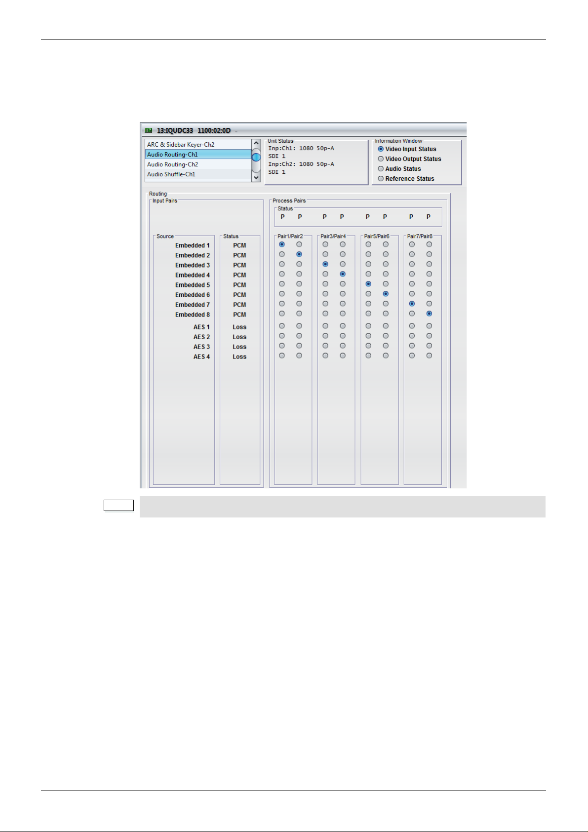
IQUDC30/IQUDC31/IQUDC32/IQUDC33 Operation Using the RollCall Control Panel
Note:
5.7 Audio Routing-Ch1 and Ch2
The Audio Routing-Ch1 and Ch2 screens are the first stage of the channel-based audio
routing, with eight process pairs available for selection. The matrix of radio buttons enable
you to route any available audio input pair to any process pair.
The Audio Routing-Ch2 screen is only applicable to the IQUDC31 and IQUDC33.
5.7.1 Input Pairs
All audio input pairs available for routing on the process channel are listed here along with
their current input status. The input pairs displayed are dependent on the product
configuration and licensing options. Each input pair corresponds to a row of radio buttons in
the routing matrix.
5.7.1.1 Source
Source lists the input sources available for routing.
• Embedded 1 –8: If the selected video input to the processing channel is capable of
carrying embedded audio, the de-embedded audio pairs will be available here. Up to
eight audio pairs are available for each processing channel.
• AES 1–8: If the AES pairs are configured as inputs on the Audio I/O AES page
screen, the input AES audio pairs will be available here. Up to eight AES audio pairs
are available for each processing channel.
Issue 1 Rev 4 Page 68 © 2016 SAM

IQUDC30/IQUDC31/IQUDC32/IQUDC33 Operation Using the RollCall Control Panel
Note:
5.7.1.2 Status
The Status box shows the input status of the corresponding audio pair in the Source list.
• PCM: Audio is PCM.
• Loss: Audio is unavailable or invalid.
• Data: Audio is non-PCM and not Dolby E.
• DolbyE: Audio is Dolby E.
5.7.2 Process Pairs
Eight output pairs are available from the routing matrix. These pairs are called the process
pairs, each of which corresponds to a column of radio buttons in the routing matrix.
• To route an input source pair to a process pair, simply select the radio button that
intersects the desired input pair row, with the desired process pair column.
5.7.2.1 Status
The Status box shows the status of the corresponding process pa ir.
• P: Audio pair routed from input sources is PCM.
• L: Audio pair routed from input sources is not detected (Loss).
• N: Audio pair routed from input sources in non-PCM.
The “N” status refers to any valid input that is non-PCM, such as Data, Dolby D, or Dolby E.
Issue 1 Rev 4 Page 69 © 2016 SAM
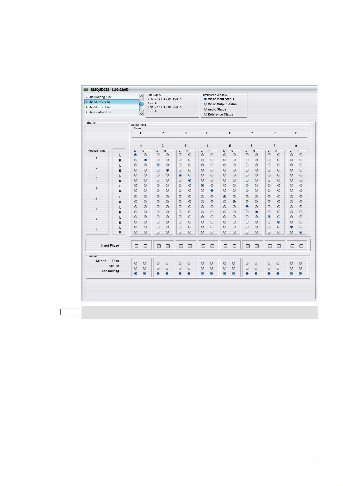
IQUDC30/IQUDC31/IQUDC32/IQUDC33 Operation Using the RollCall Control Panel
Note:
5.8 Audio Shuffle-Ch1 and Ch2
The Audio Shuffle-Ch1 and Ch2 screens enables channel-based routing for PCM audio.
Non-PCM audio is restricted to pair-based routing as channels cannot be split. The matrix of
radio buttons enable you to route any available audio input p air to any process p air, providing
this routing adheres to certain rules. See “Channel-based Routing Rules” on page 71 for
more information.
The Audio Routing-Ch2 screen is only applicable to the IQUDC31 and IQUDC33.
5.8.1 Process Pairs
The Process Pairs column shows the eight process pairs selected on the Audio
Routing-Ch1/Ch2 screen. Each of the eight pairs is split into left and right channels to allow
channel-based routing. Each process pair channel corresponds to a row of radio buttons in
the shuffle matrix.
5.8.2 Output Pairs
16 output channels available from the shuffl e matrix. These channels are gr ouped as pa irs for
output processing, such as embedding. These channels are called the ou tput pairs, each of
which corresponds to a column of radio buttons in the shuffle matrix.
• To route a process channel to an output channel, simply select the radio button that
intersects the desired process channel row, with the desired output channel column.
Issue 1 Rev 4 Page 70 © 2016 SAM

IQUDC30/IQUDC31/IQUDC32/IQUDC33 Operation Using the RollCall Control Panel
Note:
Note:
5.8.2.1 Status
The Status box shows the status of the corresponding output pair.
• P: Audio pair routed out has two channels of PCM audio.
• N: Audio pair routed out has two channels of non-PCM audio.
• T: Audio pair routed out has two channels of test-tone audio.
• S: Audio pair routed out has two channels of silent audio.
• F: Audio pair routed out has two channels of forced mute (silent) audio.
“T” (test tone) and “S” (silence) are both considered PCM audio. Therefore, according to
the channel-based routing rules, tone and silence can be routed with PCM audio. If only
one channel of the output pair is test tone or silence, its status as a pair is shown as “P”
(PCM).
5.8.3 Channel-based Routing Rules
Although channel-based routing of PCM data is possible with this mo dule, an issue may occur
when channels contain non-PCM dat a, such as Dolby E. Because of the natu re of this type of
data, a left/right pairing must remain together and be processed and routed as a pair. If not,
the encoded data can become corrupt or, most likely, meaningless. This is also true if two
channels of non-PCM data are routed together, but are not originally from the same encoding
source. Outputting an audio pair that comprises one channel of non-PCM and one of PCM
could potentially damage downstream audio equipment – it may become confused as to
whether the channels are PCM or non-PCM.
For these reasons, each time a selection is made in the shuffle matrix, the software will
compute a basic set of routing rules to guarantee that the output routing setup is valid. If the
output routing setup is invalid, the module automatically forces both channels of the output
pair to be muted. The status reporting will show “F” for force mute to indicate that this has
occurred.
Certain rules determine which combinations are valid. An invalid combination will force the
output to silence. The following table shows the rules that govern output p air comb inations.
The left-channel data type is shown in the left column, the right-channel data type is shown
across the top. The resultant status reported for the output pair is shown in the body of the
table.
Non-PCM PCM Tone Silence Loss
Non-PCM N or FFFFF
PCM FPPPF
Tone FPTPF
Silence FPPSF
Loss FFFFF
P = PCM, N = non-PCM, S = silence, T = test tone, F= forced mute (silence).
To be recognized as valid non-PCM, both channels must:
• come from the same output pair
• have the left and right channels the correct way around
• not have the phase inverted
Failing to meet these conditions will cause the pair to be muted and the Status to show “F”.
Issue 1 Rev 4 Page 71 © 2016 SAM

IQUDC30/IQUDC31/IQUDC32/IQUDC33 Operation Using the RollCall Control Panel
5.8.4 Invert Phase
The Invert Phase check boxes enable you to invert the audio phase of an output channel.
Each check box is vertically aligned with the output channel that it controls. Each channel can
be inverted independently of the other channel in its pairing. This is a useful control for
dealing with input audio discrepancies.
5.8.5 Control
Each radio button in the Control area is vertically aligned with the output channel that it
controls, and for each channel is mutually exclusive. This means that each output channel
has three modes of operation selectable.
• Tone: Output channel will output an internally generated test tone, dependant on
routing rules.
• Silence: Output channel will output internally generated silence, dependant on
routing rules.
• Use Routing: The shuffle matrix defines which process pair channel is routed to
which output channel, dependant on routing rules.
Issue 1 Rev 4 Page 72 © 2016 SAM
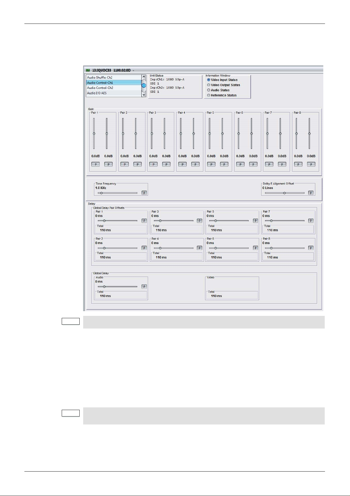
IQUDC30/IQUDC31/IQUDC32/IQUDC33 Operation Using the RollCall Control Panel
Note:
Note:
5.9 Audio Control-Ch1 and Ch2
The Audio Control-Ch1 and Ch2 screens enable you to adjust the gain of the eight output
pairs as configured on the Audio Shuffle-Ch1 and Ch2 screens.
The Audio Control-Ch2 screen is only applicable to the IQUDC31 and IQUDC33.
5.9.1 Gain
The Pair 1–8 sliders adjust the gain of the left and right channels of the output pairs. The
adjustment range is -18 dB to 18 dB in 0.1 dB steps. The preset value is 0 dB.
5.9.2 Tone Frequency
The Tone Frequency slider enables you to select the tone frequency. The selecte d freq uency
is also shown on the Audio Shuffle-Ch1 and Ch2 screen s, next to the Tone radio buttons. The
adjustment range is 0.1 KHz to 10 KHz in 0.1 KHz steps. The preset value is 1 KHz.
All 16 output channels can independently turn tone on, but as there is only one test tone
generator, it will be the same tone inserted on all channels.
Issue 1 Rev 4 Page 73 © 2016 SAM

IQUDC30/IQUDC31/IQUDC32/IQUDC33 Operation Using the RollCall Control Panel
Note:
Note:
5.9.3 Delay
The Delay controls enable you to set delay pa ir offsets and the audio delay relative to the
video delay.
5.9.3.1 Tracking Audio Delay (where fitted*)
The module measures video delay input to output, and automatically compensates the audio
via precision sample rate conversion. In this way, AV delay error is reduced to less than 2 ms.
This is ideal for content where AV timing is critical e.g. lip sync (talking heads and musical
events), and removes the need for manual adjust ment. However, user adjustable audio delay
(global and pairwise) is still additionally available, to compensate for up/down stream audio
timing errors.
*Tracking Audio Delay is not available in modules which were upgr aded to V5.2.7 or above
after installation. Only new builds of modules at version 5.2.7 and above will have tracking
audio delay.
5.9.3.2 Global Delay
The Global Delay control shows the total video and audio delay for the current video
conversion. The preset value for audio delay is the same as total vid eo delay, in order that the
two should be co-timed.
• Audio: Adjusts the audio delay relative to the video delay. The slider controls all eight
audio output pairs as a bulk gr oup. The adjustment ra nge is -40 ms to 2 00 ms in 1 ms
steps. The preset value is 0 ms.
This is actually an offset to the total video delay. The preset value of 0 ms means that
audio delay matches video. Moving the slider to -10 ms, means all eight output
channels will be 10 ms earlier than the video at the output.
The total global audio delay is displayed in the Total box: total global audio delay =
(total video delay + global audio delay).
• Video: The Total box shows the current total video delay.
Global delay is applied to all channels. Individual channel delays are added/subtracted
from this delay.
5.9.3.3 Global Delay Pair Offsets
In addition to the Global Delay controls, eight separate controls enable you to adjust each
audio output pair individually. Each slider applies an additional delay to the pair, which is
offset from the audio global delay.
• Pair 1–8: Adjusts the audio delay offset for each of the eight audio output pairs. The
adjustment range is -40 ms to 200 ms in 1 ms steps. The preset value is 0 ms.
The total global audio delay pair offset is displayed in the Total box: total global audio
delay pair offset = (total video delay + global audio delay + pair offset).
Issue 1 Rev 4 Page 74 © 2016 SAM

IQUDC30/IQUDC31/IQUDC32/IQUDC33 Operation Using the RollCall Control Panel
Note:
5.10 Audio I/O AES
The Audio I/O AES screen enables you to configure up to eight external AES connections.
5.10.1 AES 1–8
Each AES connector can be set to be either an input or an output. If set as an input, the
connectors are hard-wired to the eight AES input pairs (shown in the Input Pairs – Source list
on the Audio-Routing Ch1 screen). If set as an output, these controls select which source is
routed to the AES connector.
For each AES pair, the following list of sources is available:
• Use as Input: Sets AES connector to be an input.
• Ch 1 Pair 1: Output Pair 1 as routed on Audio Shuffle-Ch1 Routing screen.
• Ch 1 Pair 2: Output Pair 2 as routed on Audio Shuffle-Ch1 Routing screen.
• Ch 1 Pair 3: Output Pair 3 as routed on Audio Shuffle-Ch1 Routing screen.
• Ch 1 Pair 4: Output Pair 4 as routed on Audio Shuffle-Ch1 Routing screen.
• Ch 1 Pair 5: Output Pair 5 as routed on Audio Shuffle-Ch1 Routing screen.
• Ch 1 Pair 6: Output Pair 6 as routed on Audio Shuffle-Ch1 Routing screen.
• Ch 1 Pair 7: Output Pair 7 as routed on Audio Shuffle-Ch1 Routing screen.
• Ch 1 Pair 8: Output Pair 8 as routed on Audio Shuffle-Ch1 Routing screen.
• Ch 2 Pair 1: Output Pair 1 as routed on Audio Shuffle-Ch2 Routing screen.
• Ch 2 Pair 2: Output Pair 2 as routed on Audio Shuffle-Ch2 Routing screen.
• Ch 2 Pair 3: Output Pair 3 as routed on Audio Shuffle-Ch2 Routing screen.
• Ch 2 Pair 4: Output Pair 4 as routed on Audio Shuffle-Ch2 Routing screen.
• Ch 2 Pair 5: Output Pair 5 as routed on Audio Shuffle-Ch2 Routing screen.
• Ch 2 Pair 6: Output Pair 6 as routed on Audio Shuffle-Ch2 Routing screen.
• Ch 2 Pair 7: Output Pair 7 as routed on Audio Shuffle-Ch2 Routing screen.
• Ch 2 Pair 8: Output Pair 8 as routed on Audio Shuffle-Ch2 Routing screen.
If a pair is set as an output, it appears grayed out on the Audio Routing Ch1 screen.
Issue 1 Rev 4 Page 75 © 2016 SAM

IQUDC30/IQUDC31/IQUDC32/IQUDC33 Operation Using the RollCall Control Panel
Note:
Note:
Note:
5.11 Genlock
The Genlock screen provides controls for locking the output video clock to the genlock source
(input or reference) regardless of the video standard. If the genlock source and the video
output are the same frame rate, for example, 50 Hz or 59.94 Hz, Genlock locks the output to
the vertical phase of the genlock source, giving consistent and repeatable delay.
Lock to input wherever possible. Only lock to an external reference if necessary.
When attempting to pass non-PCM audio, ensure that Genlock is enabled. If using an
external reference, it must be clock-locked to the input video.
If Genlock is set to Free Run, non-PCM audio will always be corrupt.
The Source Ch2 and Timing Ch2 controls are only applicable to the IQUDC31 and
IQUDC33.
5.11.1 Source Ch 1 and Ch 2
One genlock circuit applies to channel 1 and channel 2 output video signals. The Source
menu enables you to select options for a genlock source.
• Module Reference: Locks the output video to the incoming rear-panel reference.
• Chassis Reference A: Locks the output video to incoming chassis reference A.
• Chassis Reference B: Locks the output video to incoming chassis reference B.
• Ch1 input: Locks the output video to the channel 1 input.
• Ch2 input: Locks the output video to the channel 2 input.
• Free Run: Locks the output video to an internal reference clock.
Issue 1 Rev 4 Page 76 © 2016 SAM

IQUDC30/IQUDC31/IQUDC32/IQUDC33 Operation Using the RollCall Control Panel
5.11.2 Timing Ch 1 and Ch 2
The Timing controls enable you to specify the horizontal and vertical genlock timing for each
channel.
• Vertical Timing: Adjusts the vertical timing of the output signal with respect to the
reference signal. The adjustment range is one output line in one-line steps. The
preset value is 0.
• Horizontal Timing: Adjusts the horizontal timing of the output signal with respect to
the reference signal. The adjustment range is one output frame in one-pixel steps.
The preset value is 0.
• Status: Shows the status of the currently assigned reference. For example , if genlock
is assigned to input 1, Status shows “Ch 1 Input” followed by the current status of the
input. If there is no signal on the assigned reference, Status shows “REF Loss”.
Issue 1 Rev 4 Page 77 © 2016 SAM

IQUDC30/IQUDC31/IQUDC32/IQUDC33 Operation Using the RollCall Control Panel
Note:
Note:
5.12 Timecode-Ch1 and Ch2
The Timecode-Ch1 and Ch2 screens provide timecode processing control.
For HD video inputs, ATC LTC and ATC VITC timecode data formats are supported. For HD
video outputs, the timecode data format is fixed to ATC VITC. This is present in all HD video
outputs if Follow Input mode is selected (with a valid input timecode detected), or if Generate
mode is selected.
For SD video inputs, VITC, A TC LTC and ATC VITC timecode data form ats are supported. For
SD video outputs, the timecode data format is fixed to VITC. This is present in all SD video
outputs if the VITC Enable check box is selected, and either Follow Input mode is selected
(with a valid input timecode detected), or Generate mode is selected.
External LTC timecode is not supported.
The Timecode-Ch2 screen is only applicable to the IQUDC31 and IQUDC33.
5.12.1 Source
The Source controls enable you to choose a timecode format for HD and SD input vide o: LTC
or VITC for HD, and VITC, ATC LTC, or ATC VITC for SD.
5.12.1.1 Source HD
For HD video standards, the supported input timecode format is ATC. This means that
timecode data formatted as LTC, VITC, or both will be detected at the input; however, only
one format can be selected.
• LTC: Select ATC LTC only if detected when video input is HD.
• VTIC: Select ATC VITC only if detected when video input is HD.
If the selected format is not detected at the input, no timecode processing will be available.
Issue 1 Rev 4 Page 78 © 2016 SAM

IQUDC30/IQUDC31/IQUDC32/IQUDC33 Operation Using the RollCall Control Panel
Note:
5.12.1.2 Source (SD)
For SD video standards, the supported input timecode formats are VITC and ATC. As with
HD, A TC can mean that timecode data formatted as LTC, VITC, or both will be detected at the
input; however, only one format can be selected.
• VITC: Select VITC only if detected when video input is SD.
• ATC LTC: Select ATC LTC only if detected when video input is SD.
• ATC VTIC: Select ATC VITC only if detected when video input is SD.
If the selected format is not detected at the input, no timecode processing will be available.
5.12.1.3 Status
The St atus box reports which type of embedded timecode is detected within the video inp ut to
this processing channel. If no valid timecode is detected, “None” is displayed.
5.12.2 Processing
The processing controls enable you to select a mode of operation for timecode processing.
5.12.2.1 Mode
Two modes are available for timecode processing.
• Follow Input: The input timecode is read every frame and the actual time elapsed
since timecode 00:00:00:00 is calculated. This elapsed time is then converted into an
output timecode that matches the output video frame, and inserted into the output.
There is an additional and complicated process to compensate for clock offset
between in and out, which will generate repeated or skipped timecodes as necessary,
just as happens when synchronizing at the same standard. If the output is
clock-locked to the input, this process has no effect.
• Generate: The unit generates the output timecode internally to match the output
video standard. You can specify a start time in the Timecode Entry box. See see
section 5.12.2.3 below.
5.12.2.2 On Timecode Loss
On Timecode Loss defines how the embedded output timecode should behave if input
timecode cannot be detected.
• Freeze: On timecode loss, the output timecode will freeze at the last valid detected
input value, until the valid input returns.
• Free Run: On timecode loss, the output timecode will switch to free-run and generate
its own timecode starting from the last valid detected input value, until the valid input
returns.
In Follow Input mode, only the selected source type of ANC packet is inserted into the
output video. Therefore, the action on timecode loss is only applicable to the selected
ATC type.
Issue 1 Rev 4 Page 79 © 2016 SAM

IQUDC30/IQUDC31/IQUDC32/IQUDC33 Operation Using the RollCall Control Panel
Note:
5.12.2.3 Generator
When timecode Generate mode is selected, the controls enable you to enter a specified
starting timecode of the free-running internal timecode generator.
When Generate mode is selected, both ATC LTC and ATC VITC are embedded in the
output.
• Timecode Entry: In this field you can enter a value to specify when the internally
generated timecode starts. Once set, the internally generated timecode will start when
you select the Timecode Load button. To enter a value:
In the Timecode Entry field, enter the required value and click S to set. To return to the
preset value, click P.
• Timecode Load: Manually triggers the internally generated timecode, starting at the
time specified in the Timecode Entry field.
• 30FPS: Output timecode always follows the correct count sequence for the output
standard, except when following an input timecode that does not repr esent actual
time (except if the input is flagged as 59 non-drop).
Drop Frame operates as follows:
• When converting timecode from 29/59 Hz to 29/59 Hz standards, the output
• When using the internal timecode generator with a 29 /59 Hz output st and ard, the
• When converting 23 Hz inputs to anything, follow input will give a broken
5.12.3 Embedding
The Embedding controls enable you to enable/disable embed ding of VITC in SD output video,
and to choose the line on which it is embedded for both 525 and 625 outputs.
• VITC Enable: Enables the embedding of VITC in the SD output.
Note: This control only enables the embedding of VITC. In order for VITC to be
present in the output SD video, a valid timecode must be detected at the input whe n in
Follow Input mode, or when Generate mode is selected.
• Output Line (525): Selects the output line on which VITC is p laced when the cha nnel
output is 525. The range is from line 11 to line 17 in one-line steps. The default is line
14.
• Output Line (625): Selects the output line on which VITC is p laced when the cha nnel
output is 625. The range is from line 7 to line 20 in one-line steps. The default is line
19.
drop-frame type automatically matches the input (the Drop Frame control has no
effect).
drop-frame type is determined by the Drop Frame control.
timecode sequence.
Note: The line number stated is the first of the two lines used to embed VITC. The
second line will always be the line selected + 2. For example, the default line for 525
is 14. Therefore VITC will be embedded on lines 14 and 16.
Issue 1 Rev 4 Page 80 © 2016 SAM

IQUDC30/IQUDC31/IQUDC32/IQUDC33 Operation Using the RollCall Control Panel
Note:
5.13 Metadata-Ch1 and Ch2
The Metadata-Ch1 and Ch2 scre ens enable you to control a set of closed captions and
teletext subtitle information.
The Metadata-Ch2 screen is only applicable to the IQUDC31 and IQUDC33.
5.13.1 Closed Captions
Closed Captions covers CEA-608 and CEA-708 specified captioning. Although these
specifications support captioning in multiple video standards, CEA-608 is only supported in
525 input or output as a line 21 signal. CEA-708 is only supported in 59 Hz HD video
standards as a VANC packet with a Caption Distribution Packet (CDP) payload.
Closed Caption pass-through is possible if a valid input closed caption is pres en t an d inp u t
and output video standards are the same.
Closed Caption transcoding is supported from CEA-608 to CEA-708 by taking the decoded
bytes from the line 21 signal and inserting them into the compatibility byte within the CDP.
Transcoding from CEA-708 to CEA-608 is possible if the CDP contains compatibility bytes,
which are extracted and encoded as an output line 21 signal.
Closed captions are automatically detected in the input video, and the detected format shown
in the Status window. For closed captions to be embedded in the output video, they must be
enabled. User control for on which line to embed CEA-708 is provided, but CEA-608 is always
fixed at line 21.
Issue 1 Rev 4 Page 81 © 2016 SAM
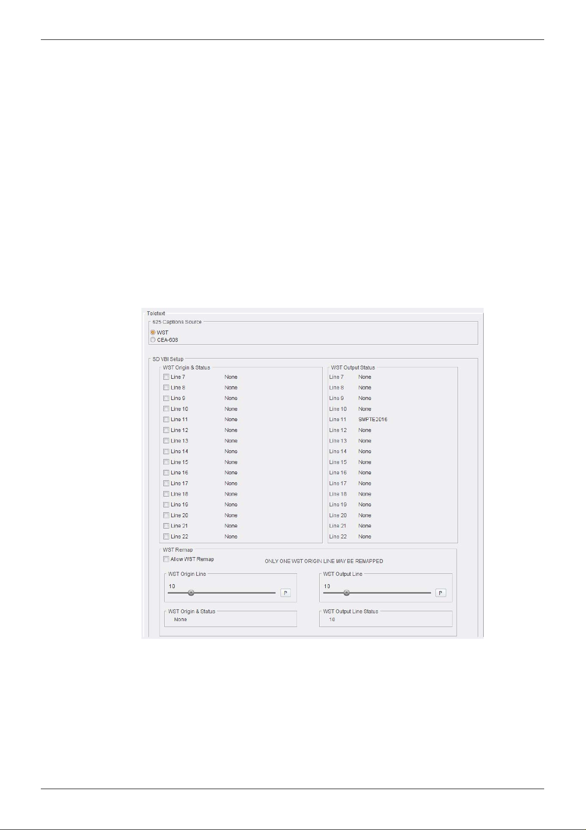
IQUDC30/IQUDC31/IQUDC32/IQUDC33 Operation Using the RollCall Control Panel
5.13.1.1 CEA608/708
• CEA-608/708 Output Enable: Enables embedding of CEA-608 captioning as a line
21 signal in 525 output video, and CEA-708 captioning as a n embedded VANC packet
in 59 Hz HD output video.
Note: The Output Enable controls only enable embedding of output closed captioning.
For closed captioning to be present in the output video, valid input closed captioning
must be detected, and you must select the correct output standard to support
pass-through or transcoding.
• Output Line: Selects the output line on which to insert CEA-708 VANC packets. The
range is from line 8 to line 20 in one-line steps. The default is line 10.
• CEA-708 Output Line Status: Shows the output line number on which CEA-708
VANC packets are inserted. If no line number is selected, “OFF” is displayed.
5.13.1.2 Status
The Status box shows if either CEA-608 or CEA-708 captions are detected on the input.
5.13.2 Multi-line WST
The unit can pass World System Teletext (WST) for SD and RDD-08 or SMPTE 2031 teletext
for HD. You can enable or disable teletext output and specify the input and output lines used.
Teletext covers World System Teletext (WST) subtitles, SMPTE RDD-08 and SMPTE 2031.
For WST and RDD-08, only subtitle information is supported or processed. SMPTE 2031
VANC packets may be teletext subtitles, non-subtitles, or inverted teletext.
WST is only supported in 625 input or output encoded signals. RDD-08 is only supported in
50 Hz HD video standards as a VANC packet with a Subtitling Distribution Packet (SDP)
payload. Teletext subtitle transcoding is supported from WST to RDD-08 by taking the
Issue 1 Rev 4 Page 82 © 2016 SAM

IQUDC30/IQUDC31/IQUDC32/IQUDC33 Operation Using the RollCall Control Panel
decoded bytes from the WST signal and inserting them into the payload within the SDP (see
below). Transcoding from RDD-08 to WST is only possible if the SDP contains valid subtitles,
which are extracted and encoded as an output WST signal.
Teletext pass-through
Teletext pass-through is possible if a valid input teletext subtitle is present and input and
output video standards are the same. For SD video that uses a large number of WST VBI
(where the VBI may have multiple lines of WST and 2 Timecode lines) the unit can
encode/decode/transcode up to 15 lines of WST. In up and down conversion applications, this
would use up to 3 RDD-08 (OP47) packets. RDD08 OP47 allows for 15 lines of WST to be
encoded. SMPTE2031 allows only 5 lines of WST to be encoded,
625 Input - 625 Output
Y o u can select which input lines of WST a re encoded on the output. For the line s selected the
status of WST being detected on that line is reported back.
The unit allows for up to 15 lines of WST to be selected on the input. If valid WST is detected
on the selected lines, they will be placed on the same lines on the output. The status for each
line will be reported back.
It is also possible to remap one WST origin line. In this case, select Allow WST remap. If valid
WST is detected on the line selected by “WST origin line” it will be put on the line selected by
the user control “WST output line”.
Issue 1 Rev 4 Page 83 © 2016 SAM
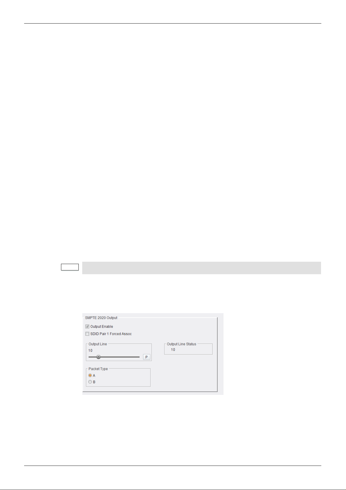
IQUDC30/IQUDC31/IQUDC32/IQUDC33 Operation Using the RollCall Control Panel
Note:
625 Input - HD Output
In applications where the video is upconverted, you can select which lines of WST are
encoded.
1. If RDD08 (OP47) conversion is selected, then up to 15 lines can be encoded in the
RDD-08 packet. A maximum of 3 packets are allowe d on the output, each with
individual line number controls. The number of output RDD-08 packets on the output
is decided by the number of valid WST lines decoded on the input. The first five WST
lines are encoded in the first RDD-08 packet, th e next 5 in the seco nd RDD-08 p acket
and so on.
2. If SMPTE2031 conversion is selected, then the first 5 lines selected on the input are
encoded in the 2031 packet. Each single WST line corresponds to one SMPTE2031
packet on the output. All packets will be placed on the same line selected by the user
control (Output Line All PKTs). The Data Unit ID can be set to Teletext Subtitle,
Teletext Non-Subtitle or Inverted Teletext.
HD Input - HD Output
You can select which input HD WST packet is to be decoded - RDD-08 or SMPTE2031.
Cross-conversion between the packet types is allowed. The option to select individual WST
lines contained in the input packets is still available using the WST origin and status menu
items. This is because both the SMPTE2031 and RDD-08 packet contain within them the
original source SD line number information. The input line selection refers to this line number
and not the ANC packet position line number.
HD Input - 625 Output
You can select which input HD WST packet is to be decoded - RDD-08 or SMPTE2031 . You
can specify which lines of WST to encode on the output using the WST origin and menu item.
The WST lines will be encoded on the line number information encoded within the input HD
packet, unless “Allow WST rema p” is selected in which case you can change the line number
for one WST line on the output (similar to the SD to SD case described previously).
Only one WST origin line may be remapped.
5.13.3 SMPTE 2020 Output
SMPTE 2020 Output: Selects the output line on which to insert a SMPTE 2020 VANC packet
if the output is enabled. The range is from line 8 to line 20 in one-line steps. Preset is line 10.
It is possible to set a forced association in the SMPTE 2020 metadata which sets the
Secondary Data ID (SDID) values used to identify the VANC packets to 45/02 (pair 1).
To use this control, enable “SDID Pair 1 Forced Assoc” from the Dolby menu under the
sub-menu SMPTE 2020 Output. When enabled, the outgoing 2020 data will be labelled
45/02 (pair 1).
Issue 1 Rev 4 Page 84 © 2016 SAM
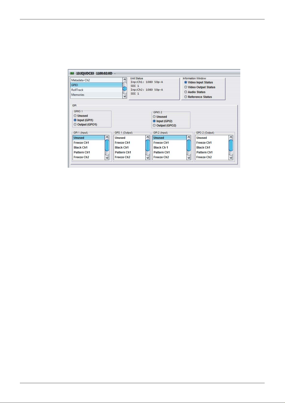
IQUDC30/IQUDC31/IQUDC32/IQUDC33 Operation Using the RollCall Control Panel
5.14 GPIO
The GPIO screen enables you to configure General Purpose Interface Input/Output functi ons.
If a rear panel with GPIO screw terminal connections is fitted, the controls on this screen will
be active. The screw terminal connector provides two GPIOs that can be configured as either
an input or an output.
5.14.1 GPIO 1 and 2
• Unused: GPI is inactive.
• Input: Configures GPI as an input.
• Output: Configures GPI as an output.
5.14.2 GPI 1 and 2 (Input)
When the GPI is configured as an input, a low to high transition will trigger the GPI input
function. Each of the following options is initial-edge triggered. Once this has ta ken place, the
option remains selected until some other process is initiated.
• Freeze Ch1: The output picture will be frozen and the Freeze check box on the
Output screen selected.
• Black Ch1: The output picture will be black and the Test Patterns – Black radio button
on the Output screen selected.
• Pattern Ch1: The output picture will be a ramp and the Test Patterns – Ramp radio
button on the Output screen selected.
• User Memory 1 to 16: Any saved user memories will appear in the GPI Input list. The
default memory name is “User Memory N”, where N is the memory number from 1 to
16.
The name that appears here is the same as that on the Memories screen. Triggering
this input will perform a memory recall exactly as it would on the Memories screen.
Issue 1 Rev 4 Page 85 © 2016 SAM

IQUDC30/IQUDC31/IQUDC32/IQUDC33 Operation Using the RollCall Control Panel
5.14.3 GPI 1 and 2 (Output)
When the GPI is configured as an output, this enables you to choose an action that will
produce an output signal at the GPI connector. The GPI output will be driven to low when the
action is true or high when false.
• Freeze Ch1: GPI output will be driven low when freeze is selected, and will return
high when freeze is deselected.
• Black Ch1: GPI output will be driven low when Test Patterns – Black is selected on
the Output screen, and will return high when Test Patterns – Black is deselected.
• Pattern Ch1: GPI output will be driven low when Test Patterns – Ramp is selected on
the Output screen, and will return high when Test Patterns – Ramp is deselected.
Issue 1 Rev 4 Page 86 © 2016 SAM
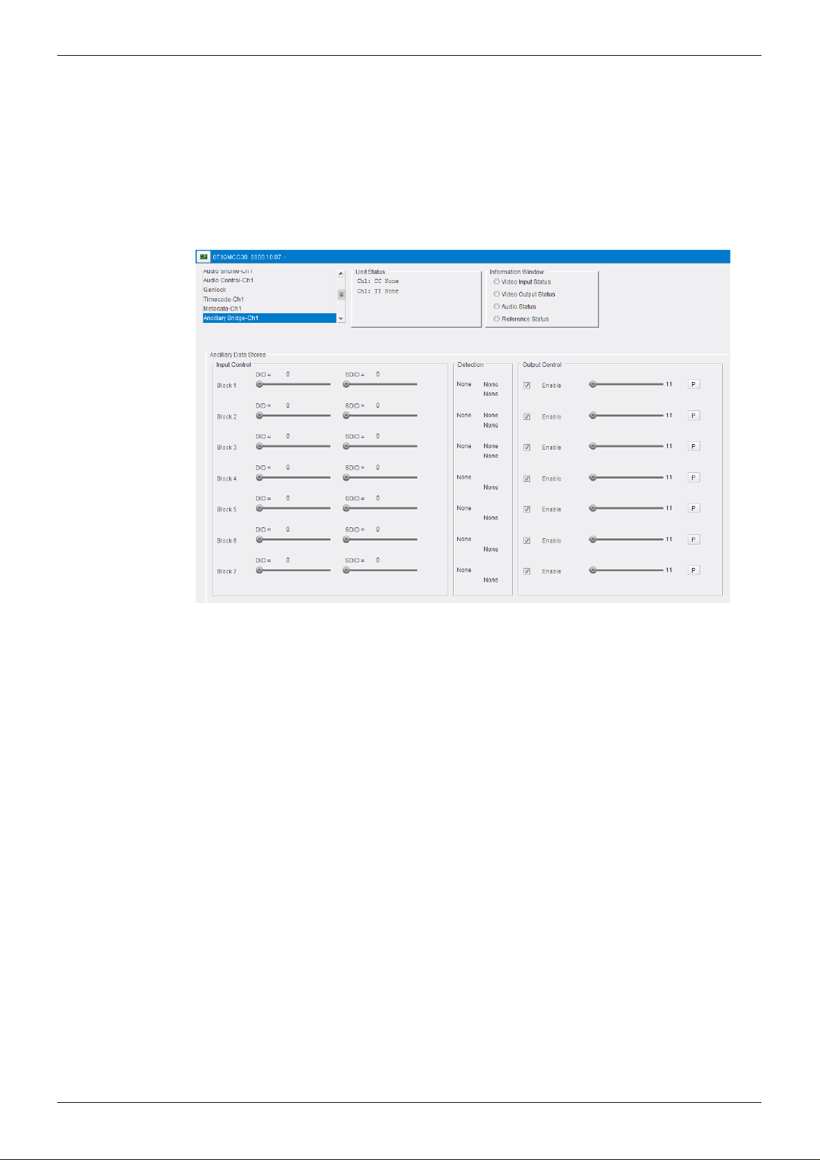
IQUDC30/IQUDC31/IQUDC32/IQUDC33 Operation Using the RollCall Control Panel
5.15 Ancillary Bridge-Ch1,Ch2
The Ancillary Bridge allows detection of packet based ancillary data and re-insertion on the
output (unaltered). This should not be used for packet types alr eady processed (708, RDD08,
SMPTE2016, SMPTE2031, ATC) by the ancillary data block. The exception is in processing
SD-ATC, where you should use the bridge.
You can select the ANC packet type to be transferred and the line number at the output on
which the transferred packet is to appear, then the bridge operates automatically when
enabled.
5.15.1 Operation
1. Select the ANC packet type to be transferred using the DID and SDID Input Controls.
2. Select the output line using the Output Control (default is 11).
3. Check the Enable box in Output Control (default is enabled).
5.15.2 Warnings
• The ANC bridge can only transfer up to seven different ANC packet types.
• For each of the seven ANC types, only one packet can be handled at a time. When a
packet has been read from the input, until its nominated output line occurs and the
packet is read from the store, any other packets of th e same type are ignor ed. No line
number is reported for a packet which has been ignored.
• No changes can be made to the ANC packets; they are forwarded exactly as
received.
• There is no control to reset the stores. When not in use they should left reading DIDs
which never occur such as 0 or 255 so that old packets aren't transmitted when the
output line numbers are programmed.
• There is no check of remaining ancillary space at the start of a packet transmit. ANC
packet length is from 4 to 259 words but the packet lengths are not reported to the
CPU. Errant packets are corrupted by the syncs they try to overwrite.
Issue 1 Rev 4 Page 87 © 2016 SAM

IQUDC30/IQUDC31/IQUDC32/IQUDC33 Operation Using the RollCall Control Panel
5.15.3 Special features
• If more than one of the stores is set to transmit in the same space (HANC or V ANC) of
the same line, the packets will be transmitted in ascending order of store number.
• More than one store can be set to pass the same type of packet. The lowest
numbered empty store is used. Different input fields and output line numbers can be
used.
• The line number on which an input packet occurs and whether it was in HANC or
VANC is reported each store. These registers are cleared after they are read so
subsequent reads will say 0 - valid line numbers are from 1. This is how to tell whether
the nominated ANC packets are occurring or not (a valid output line number must be
set since new packets aren't reported whilst a store is full).
• If the DID for a store is set to 128 or greater, the SDID register is ignored and all
packets with that DID can be passed through that store. (These packets are type 1
and the place of the SDID is taken by a data block number.)
• A range of up to 32 SDIDs can be matched for a gi ven DID by setting the SDID range
bits for a store.
To pass a single SDID, set the range to 0.
For Dolby metadata (SMPTE 2020-1) the SDIDs can be from 1 to 9 so the SDID
would be 1 and the range 8.
Issue 1 Rev 4 Page 88 © 2016 SAM

IQUDC30/IQUDC31/IQUDC32/IQUDC33 Operation Using the RollCall Control Panel
5.16 RollTrack
The RollTrack screen allows information to be sent, via the RollCall™ network, to other
compatible units connected on the same network.
5.16.1 Disable All
The Disable All check box disables all RollTrack functions.
5.16.2 Index
The Index slider enables you to set up five different RollTrack outputs.
5.16.3 Source
The Source list specifies the source of the information that triggers the data transmission.
Unused No RollTracks sent.
Input Present Input is detected and valid.
Input Loss Input is not detected.
Reference OK Selected reference is detected and valid.
Reference Lost Selected reference is not detected.
5.16.4 Address
Address enables you to select the address of the selected destination unit.
The full RollTrack address has four sets of numbers, for example, 0000:10:01*99.
• The first set, 0000 in the example, is the network segment code number.
• The second set, 10 in the example, identifies the enclosure/mainframe unit.
• The third set, 01 in the example, identifies the slot number in the unit.
• The fourth set, 99 in the example, is a user-defined number that identifies the
destination unit in a multi-unit system. This ensures that only the correct unit respon ds
to commands. If left at 00, an incorrectly fitted unit may respond unexpectedly.
Rolltracks can be internally looped back using address FFFF:00:00.
Issue 1 Rev 4 Page 89 © 2016 SAM

IQUDC30/IQUDC31/IQUDC32/IQUDC33 Operation Using the RollCall Control Panel
5.16.5 Command
Command enables a command to be sent to the selected destination unit. Each RollT rack
command comprises two sets of numbers, for example, 33039:3.
• The first set, 33039 in the example, is the RollTrack command number, which
identifies the command.
• The second set, 3 in the example, is the value sent with the command.
5.16.6 RollTrack Sending
Rolltrack Sending shows information when the unit is sending a RollTrack command.
No The command is being sent.
Yes The command is being sent.
5.16.7 RollTrack Status
RollTrack Status shows information about the status of the selected RollTrack Index.
OK RollTrack message sent and received OK.
Unknown RollTrack message has been sent but has not yet completed
Timeout RollTrack message sent, but acknowledgement not received. This
could be because the destination unit is not at the specified location.
Bad RollTrack message has not been acknowledged at the destination
unit. This could be because the destination unit is not of the type
specified.
Disabled RollTrack sending is disabled.
5.16.8 Configuring a RollTrack Action
1. Use the Index slider to select the Index number. This identifies the RollTrack action
being configured. You can create up to five RollTrack actions.
2. From the Source list, select the source that will trigger RollTrack transmission.
3. In the Address field, enter the RollTrack address and click S to set. To return to the
preset value, click P.
4. In the Command field, enter the RollTrack command and click S to set. To return to
the preset value, click P.
5.16.9 Viewing RollTrack Information
See see section 5.16.6 and see section 5.16.7.
Issue 1 Rev 4 Page 90 © 2016 SAM

IQUDC30/IQUDC31/IQUDC32/IQUDC33 Operation Using the RollCall Control Panel
Note:
Note:
5.17 Memories
The Memories screen enables you to save up to 16 memory setups and recall them when
required.
You can change the default memory names to more relevant ones if required.
You can store and recall all control in a user memory exce pt for the follo wing sections: Log
Enable, RollTrack, GPIO, Memories.
5.17.1 Saving Memory Settings
• In the Save Memory column, select a memory location and click Save. The current
settings are saved and the memory appears in the Recall Memory column.
5.17.2 Changing a Memory Name
• In the Save Memory Name field, type the new memory name and click S to set. To
return the memory to its preset value, click P.
5.17.3 Recalling a Memory
The Recall Memory list recalls the settings saved in a memory location. The Last Recalled
Memory box shows the most recently recalled memory.
To recall a memory:
• In the Recall Memory column, select the memory you want to recall. The recalled
settings are applied and the memory name appears under Last Recalled Memory.
Memories do not recall log field states, such as whether a log value is enabled or disabled.
5.17.4 Last Recalled Memory
The Last Recalled Memory box shows the most recently recalled memory.
Issue 1 Rev 4 Page 91 © 2016 SAM

IQUDC30/IQUDC31/IQUDC32/IQUDC33 Operation Using the RollCall Control Panel
5.18 Logging
Logging makes information about various parameters available to a logging device connected
to the RollCall network.
Each logging screen has three columns:
• Log Enable: Use the check boxes to select the parameters for which log information
should be collected.
• Log Field: Shows the name of the logging field.
• Log Value: Shows the current log value.
5.18.1 Misc. Logging
The Misc-Logging screen shows the current log information for the unit’s basic parameters.
Log Field Description
SN= The module’s unique serial number. Note: this cannot be
deselected.
UPTIME= Shows the time since the last restart (format ddd:hh:mm:ss).
POWER USAGE= The power rating for the module. Note: this is not a live power
reading, but a maximum power rating.
BUILD= The factory build number. This number identifies all
parameters of the module.
Issue 1 Rev 4 Page 92 © 2016 SAM

IQUDC30/IQUDC31/IQUDC32/IQUDC33 Operation Using the RollCall Control Panel
Note:
5.18.2 Video Input Logging
The Video Input Logging screen displays the current log information for the video inputs.
Up to five inputs are available. Inputs 1 & 2 are serial SDI and are present on all variants of
rear panel. Input 3 is CVBS (if fitted). Inputs 4 & 5 are SFP inputs (if fitted).
SFP inputs appear if a rear panel with an SFP connection is fitted. The SFP input selections
will appear grayed out if either no SFP module or an unsupported SFP module is inserted in
the rear panel connector.
Inputs are the physical connections to the rear panel and not inputs to the processing
channels.
Log Field Description
INPUT_N_TYPE= The type of input as specified by the module’s configuration:
• HD/SD/3G SDI – SDI BNC serial input connection
INPUT_N_STATE= The current input state:
• OK – Input signal is good
• Fail – Input signal is not detected
INPUT_N_STANDARD= The current input standard. See supported input standards
information.
Issue 1 Rev 4 Page 93 © 2016 SAM

IQUDC30/IQUDC31/IQUDC32/IQUDC33 Operation Using the RollCall Control Panel
Note:
Note:
5.18.3 Ref/Output Logging
The Ref/Output Logging screen displays the current log info rmation for the externa l reference
inputs, and the output of each processing channel.
The Reference field is present if a rear panel with external reference inpu t connection is fitted.
Output 1 is always present on all variants of rear panel. Output 2 is present on dual-channel
product variants.
The outputs are not the physical connections to the rear panel, but the output of the
processing channels.
Log Field Description
OUTPUT_N_TYPE= The type of output as specified by the module’s configuration:
• HD/SD SDI – SDI BNC serial input connection
OUTPUT_N_STATE= The current output state:
• OK – Input signal is good
• Fail – Output signal error
OUTPUT_N_ST ANDARD= The current output standar d. See supported output st andards
information.
Output 2 is only applicable to the IQUDC31 and IQUDC33.
Issue 1 Rev 4 Page 94 © 2016 SAM

IQUDC30/IQUDC31/IQUDC32/IQUDC33 Operation Using the RollCall Control Panel
Note:
Note:
5.18.4 O/P Audio State Ch1 and Ch2 Logging
The O/P Audio State Ch1 and Ch2 Logging screens display the state of the eight audio pairs
from the respective output processing channel. These are the eight audio output pairs
selected on the Audio Shuffle-Ch1 and Ch2 screens.
The outputs are not the physical connections to the rear panel, but the output of the
processing channels.
Log Field Description
OUTPUT_N_EMBEDDED_AUDIO_N_STATE= The audio output state as specified by the
module’s configuration:
• HD/SD SDI – SDI BNC serial input
connection
The Output Audio State Ch2 Logging screen is only applicable to the IQUDC31 and
IQUDC33.
Issue 1 Rev 4 Page 95 © 2016 SAM

IQUDC30/IQUDC31/IQUDC32/IQUDC33 Operation Using the RollCall Control Panel
Note:
Note:
5.18.5 O/P Audio Type Ch1 and Ch2 Logging
The O/P Audio Type Ch1 and Ch2 Logging screens display the state of the eight audio pairs
from the respective output processing channel. These are the eight audio output pairs
selected on the Audio Shuffle-Ch1 and Ch2 screens.
The outputs are not the physical connections to the rear panel, but the output of the
processing channels.
The Output Audio Type Ch2 Logging screen is only applicable to the IQUDC31 and
IQUDC33.
Log Field Description
OUTPUT_N_EMBEDDED_AUDIO_N_TYPE= The audio output type as specified by the
module’s configuration:
•PCM
•Non-PCM
•Tone
• Silence
•Loss
Issue 1 Rev 4 Page 96 © 2016 SAM
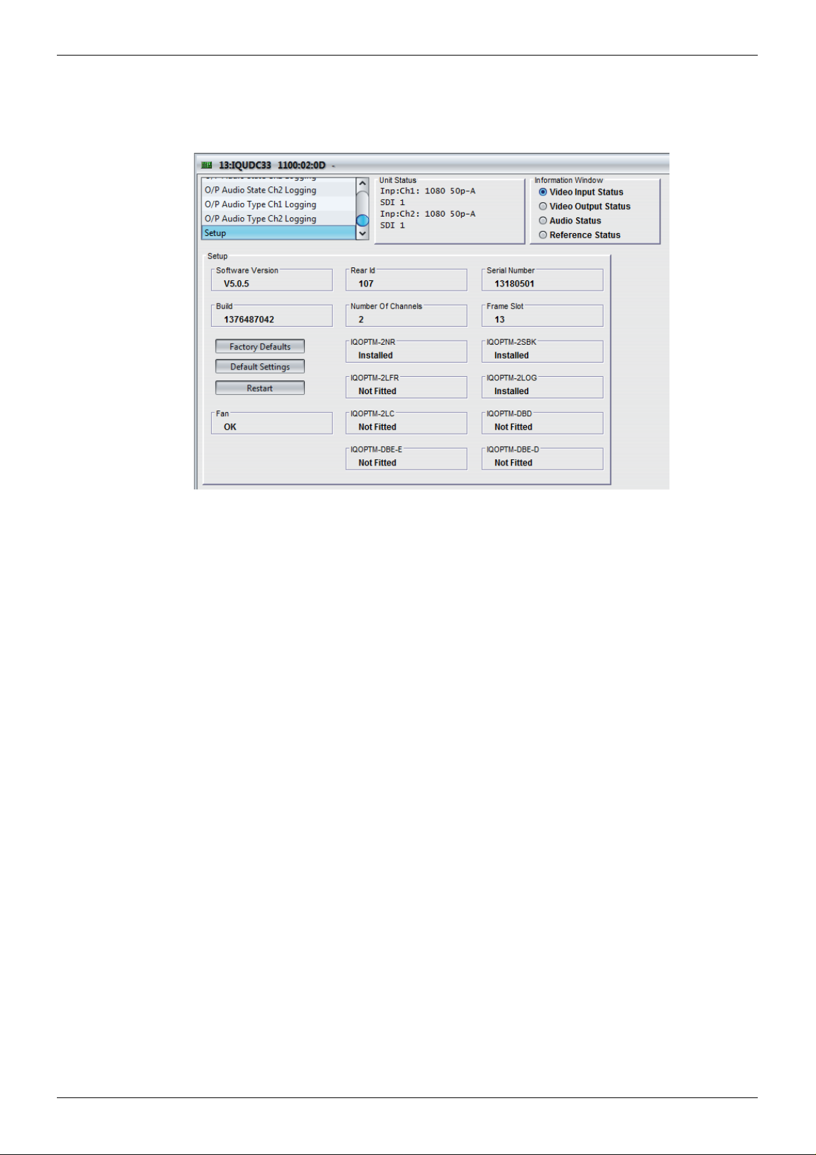
IQUDC30/IQUDC31/IQUDC32/IQUDC33 Operation Using the RollCall Control Panel
5.19 Setup
The Setup screen displays basic information about the unit such as the serial number and
software version.
• Software Version: The currently installed software version.
• Rear ID: The rear panel ID number.
• Serial Number: The module’s serial number.
• Build: The factory build number. This number identifies all parameters of the module.
• Number of Channels: The number of processing channels.
• Frame Slot: The module’s current frame slot.
• Fan: Fan status.
• Licensed Options: (For example, IQOPTM-2NR.) Shows which licensed options are
installed. If a licensed option has not been purchased, its status shows “Not Fitted”.
For more information on licensed options, see “Software Options” on page 11.
5.19.1 Factory Defaults
The Factory Defaults button resets the module setting s to their factory de fault s , and clears all
user memories.
5.19.2 Default Settings
The Default Settings button resets the module settings to their factory defaults, leaving user
memories intact.
5.19.3 Restart
The Restart button reboots the module, simulating a power-up/power-down cycle.
Issue 1 Rev 4 Page 97 © 2016 SAM

IQUDC30/IQUDC31/IQUDC32/IQUDC33 Linear Frame Rate Converter Option
Appendix 1 Linear Frame Rate Converter Option
If the IQOPTM-LC or IQOPTM-2LC option is fitted, the module will of fer one (LC) or two ( 2LC)
channels of linear frame rate conversion.
In this case, additional output frame rates will be available for each input frame rate.
For example, an incoming signal at 1080 50i can be converted to 1080 59i.
Simple conversion set-up: worked example assuming SDI I/O
1. Connect 1080 50i SDI input to Serial In 1.
2. Connect the desired reference signal to either of the two BNCs available on Ref In
(this is optional if free run or input lock are required).
3. Connect monitor to Serial Out 1.
4. Connect required downstream equipment to Serial Out 2.
5. Navigate to the Output page.
6. Select the desired output format and standard e.g. 1080 59i.
7. Navigate to the Genlock page
8. Select the appropriate genlock source (reference, input or free-run).
You are now converting 1080 50i video to 1080 5 9i, the ou tput of wh ich ca n be vi ewed o n the
monitor you have connected in step 3.
You can verify the input, output and reference status using the information window.
To view the required status select from:
• Video Input Status
• Video Output Status
• Reference Status
Figure 1Video Input Status
Figure 2Video Output Status
Figure 3Reference Status
Issue 1 Rev 4 Page 98 © 2016 SAM
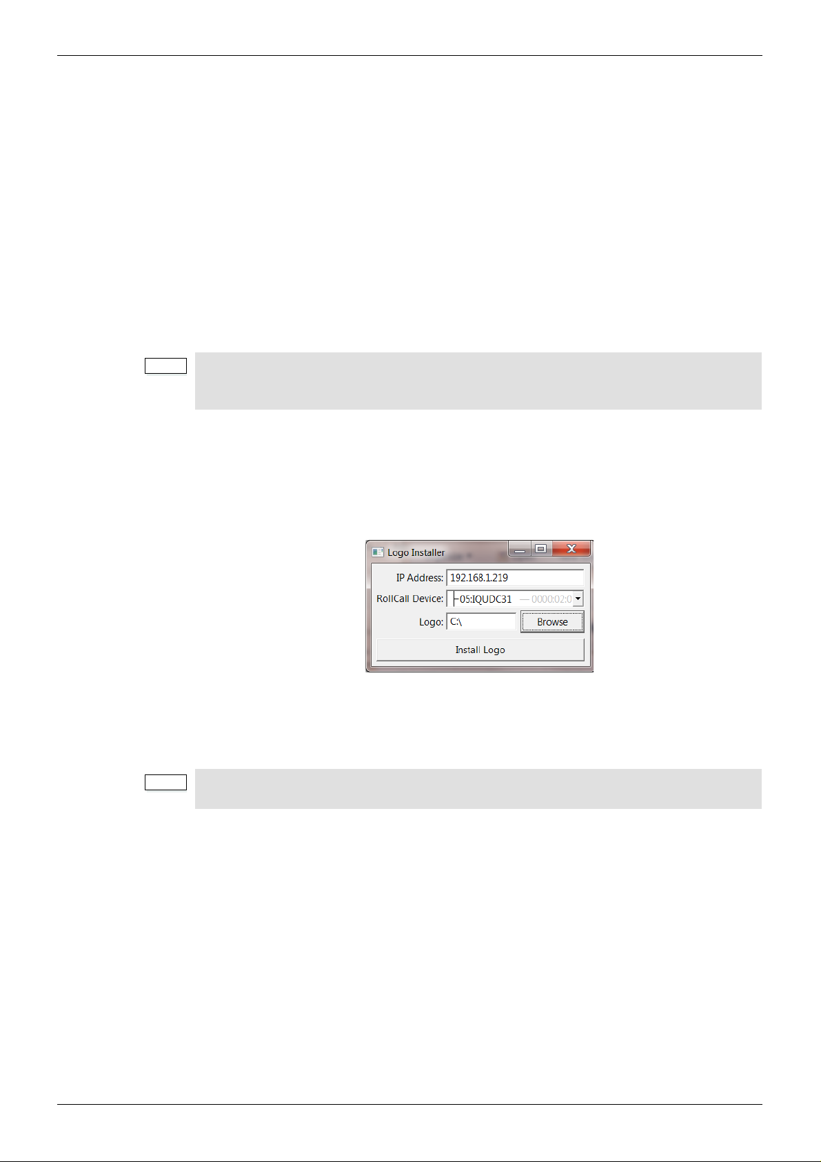
IQUDC30/IQUDC31/IQUDC32/IQUDC33 Logo Insertion
Note:
Note:
Appendix 2 Logo Insertion
2.1 Logo Insertion Introduction
The logo insertion option provides the facility to key an imported static or animated graphics
image onto the video output. The logo inserter accepts most common graphics formats and
will generate video format specific files with the appropriate interlace and color gamut for
keying onto the output video without rescaling.
To use the logo inserter, first upload logos onto the module using the logo uploader
application (see section 2.2). Then, access the logo insertion controls via the Output Co ntrol
(see section 5.3.10).
Logos of size up to 400 pixels by ¼ picture height (maximum 480 lines) can be displayed. The
logo sequence capacity is 10,000,000 pixels (approx 44s for 150x50 @ 60Hz), and the
module can store up to 64 logos.
When using the logo insertion feature with input and output signals of the same frame rate
and format, ensure that Sync Mode (see section 5.6.1) is enabled to preserve output
quality.
2.2 Logo Uploader
To upload logos onto the module, run the logo upload application on your PC. A dialog box
will appear as shown below:
Enter the IP address of your IQ frame and choose the module you wish to load the logo into
Then browse to the folder containing your required logos, and click “Install Logo”. This will
upload the logo to your unit.
This stage can take up to a minute depending on the length of the logo. Short or static
logos will upload in a few seconds.
Issue 1 Rev 4 Page 99 © 2016 SAM

IQUDC30/IQUDC31/IQUDC32/IQUDC33 Logo Insertion
2.3 Filename convention
Logos must be packaged in a directory with the same n ame as the lo go . Logo files must take
the form <logo_name><specifier>.<extension> where <logo_name> equals the directory's
name.
A <specifier> of the form _<standard> indicates that this logo is intended for this specific
standard. If no _<standard> specifier is included, then this logo is the default for any
standards which do not have a standard-specific logo.
Possible values for <standard> are: 525i, 625i, 720p, 1080p and 1080i.
A <specifier> of the form _<index> indicates that this file is part of a multi-file sequence for an
animated logo. Any non-negative decimal value may be used for <index>. The files in a
sequence are sorted in increasing order of their respective <index>es by numerical value.
Leading zeros do not affect the sort order, and it is not required that the <index> values are
contiguous, however all images in a multi-file sequence must have the same width and
height.
If both _<standard> and _<index> specifiers are used, then they should be written as
_<standard>_<index>, not _<index>_<standard>.
The <extension> is not used as the logo option will auto-detect the image format.
Examples of valid logo filenames are:
Logo name Type of logo
C:\logos\brandlogos\brandlogo.jpg Single logo jpeg file
C:\logos\brandlogos\brandlogo_625i.png
C:\logos\brandlogos\brandlogo_1080i.png
C:\logos\brandlogos\brandlogo_001.tiff
C:\logos\brandlogos\brandlogo_002.tiff
....
C:\logos\brandlogos\brandlogo_064.tiff
Two versions of the logo targeting
different output sta ndards
Animated logo of sequence length 64
2.4 Displaying logos
You can access the logo insertion controls via th e Outp ut Co ntrol (see section 5.3.10) . Se lect
the logo from the list and adjust its position and transparency as required.
The logo files should contain a key (there is no “self key” option), but if no key is found then
the entire logo image will be displayed, i.e. a rectangle cut-out of the logo image size.
RGB graphics formats are automatically converted to SD and HD colo r spaces and lev els .
YUV graphics will be presented as is for both HD and SD. The YUV range is assumed to be
16 (black) to 235 (white). Other values are clipped. Key channel levels for all g raphics formats
are 0 (off) to 255 (100% key).
In linear mode “Transp arency” controls both key gain and logo gain; in pre-shaped mode only
key gain is controlled.
Issue 1 Rev 4 Page 100 © 2016 SAM
 Loading...