

Page 1
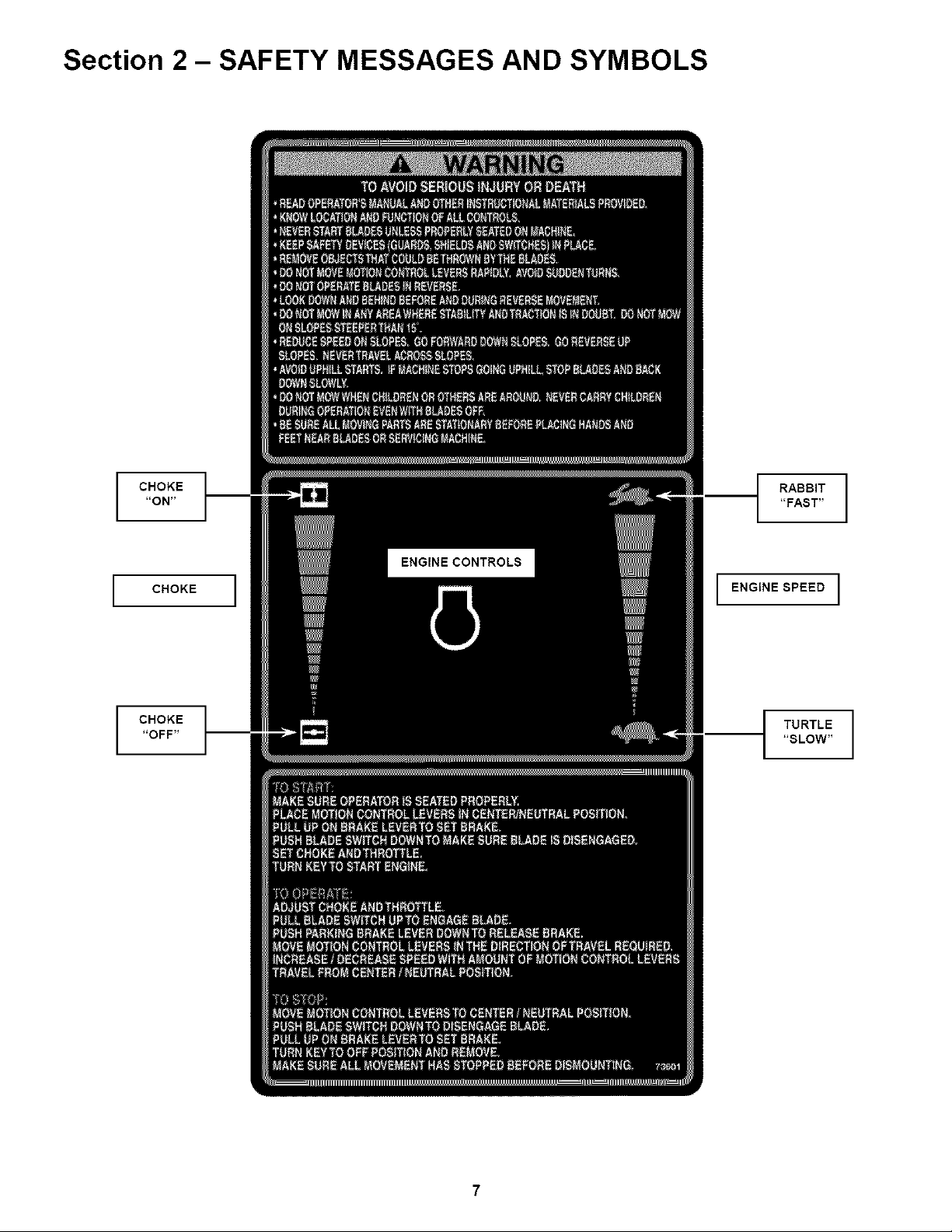
Section 2 - SAFETY MESSAGES AND SYMBOLS
CHOKE
"ON"
"FAST"
RABBIT I
CHOKE ]
CHOKE
"OFF"
I ENGINE SPEED I
TURTLE
"SLOW"
7
Page 2
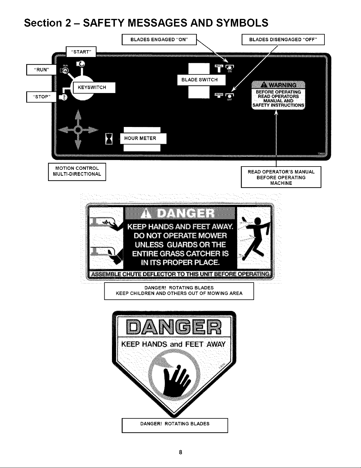
Section 2 - SAFETY MESSAGES AND SYMBOLS
I BLAOBSENGAGBO"ON"I BLAOBSDISENGAGED"OFF"I
"START"
MOTION CONTROL
MULTI-DIRECTIONAL
BEFORE OPERATING
I READ OPERATOR'S MANUAL I
MACHINE
KEEP CHILDREN AND OTHERS OUT OF MOWING AREA
I DANGER! ROTATING BLADES
DANGER! ROTATING BLADES
8
Page 3

Section 5 - ADJUSTMENTS & REPAIR
5.2 MOWER DECK & COMPONENT ADJUSTMENTS
DANGER _1
Exercise EXTREME CAUTION when making this I
adjustment, due to close proximity of moving parts, I
5.1 NEUTRAL POSITION ADJUSTMENTS
The joystick controls the movement and stopping of
the machine. Move the joystick to the center or
neutral position to stop machine. IMPORTANT:
Always return the joystick with hand assistance
to the neutral position. If machine does not come
to a complete stop or has any movement when
joystick is moved to the neutral position,
adjustment must be made.
1. Turn keyto "OFF' position.
2. Raise both wheels off the ground. Wheels should
be high enough to rotate freely. Secure with safety
blocks.
3. Disconnect parking brake rod from parking brake.
See Figure 4.3.
4. Engage parking brake lever. NOTE: Engaging
parking brake without brake rod connected will lock
joystick in center or neutral position.
5. Turn key to start position and start unit.
6. Both wheels should not have any movement, not
rotating.
7. If wheel(s) are rotating, disconnect transmission
control rods from cross shaft and turn adjusting bolts
located on pump(s) clockwise, or counter-clockwise,
until wheel(s) stop rotating. See Figure 5.1
8. With wheels in neutral, (not rotating) stop engine
and readjust control rods until they fit into the cross
shaft arms with no wheel creep.
9. Reconnect park brake red.
The following mower deck and component
adjustments and repairs can be made by the owner.
However, if there is difficulty in making these
adjustments and repairs, it is recommended that
these repairs be made by an authorized SNAPPER
dealer.
5.2.1. MOWER DECK ADJUSTMENT (LEVELNESS
SIDE to SIDE and FRONT to REAR
Before making deck leveling adjustments
check tires and add or release air as needed to
bring pressure to 12 psi in drive tires, Pressure
in front caster wheels should be 25 psi.
If tires are properly inflated and mowing is still
uneven, adjust deck levelness as follows:
SIDE to SIDE LEVEL
1. Place machine on a smooth level surface.
2. Check blade tips by rotating blades until tips
are pointing to the sides of the deck. Check the
measurement of outside blade tips to the
ground on both blades. The measure-ment of
each of the outside blade tips should be within
1/8" of each other. If measurement of the blade
tips is not within 1/8", adjustment should be
made to the higher side of the deck to lower it
to within the correct measurement.
3. Move deck lift lever and set the mower deck
to the highest cutting position.
4, Place a wooden block under the front and
rear edge of the mower deck.
5. Move deck lift lever and set the mower deck
to a lower cutting position until deck rests on
wooden blocks.
ADJUSTING BOLTS
FIGURE 5.1
18
(Continued on Next Page)
CONTROL ROD
\ TRANSMISSION
FIGURE 5.1A
Page 4

Section 5 - ADJUSTMENTS & REPAIR
5.8
MOWER SPINDLES (Field Serviceable Spindles)
BEARING REPLACEMENT
In the event that a spindle bearing requires
replacement, the SNAPPER Field Serviceable
Spindles have been designed so that no special
tools or presses are required.
1. Remove belt. Loosen blade nut and remove.
Allow blade bolt, washer, blade and four spacers to
drop down out of the spindle housing. See Figure
5.10.
5. Thoroughly clean all parts removing all otd
contaminated grease.
6. Install new bottom bearing first.
NOTE: The bearing is sealedlshielded on one
side only. The bottom bearing must be installed
with the sealedtshielded side DOWN.
7. Insert spindle shaft up through the bottom
bearing. Slide spacer down over spindle shaft.
8. Install new top bearing. Install the top
bearing with the seal/shield UP.
9. Slide circular retaining ring down spindle
shaft until it fully locks into groove on shaft.
10. Place spindle pulley and spacer on top of
spindle shaft.
11. Reinstall blade bolt, washer, blade and four
spacers.
12. Torque blade bolt and nut to 60 to 75 ft. Ibs.
IMPORTANT: Spindle housing must be filled
with grease before operating mower. Failure
to fill housing will cause premature bearing
failure.
FIGURE 5.10
2. Remove spindle pulley from spindle shaft.
3. Locate circular retaining ring on spindle shaft at
top bearing. Remove retaining ring. Allow spindle
shaft to drop out of housing.
4. Top and bottom bearings are now removable.
Pull out on inner race to slide bearing from
housing. See Figure 5.11.
÷
........,,,,,,,,,,.....
BEARING
SEAL UP
;,,,,,,,,,,,,,,,,,,,,,,,#
HOUSING
SPACER ------O _
BEARING _ ¢
PULLEY
RING
,,,,,,,........,,,,,,,,,,......
BEARING SEAL
DOWN
13. Pump grease into spindle housing until
grease purges from vent on housing.
14. After the first 5 hours of operation, grease
spindle housing to insure it is fuji, then every 25
hours.
FIGURE 5.11
24
Page 5

Safety Instructions & Operator's Manual for
MID MOUNT Z-RIDER
ZERO TURNING
HYDRO DRIVE
SERIES 0
IMPORTANT
Snapper products are built using engines that meet or exceed all applicable emissions requirements on the
date manufactured. The labels on those engines contain very important emissions information and critical
safety warnings. Read, Understand, and Follow all warnings and instructions in this manual, the engine
manual, and on the machine, engine and attachments. If you have any questions about your Snapper product,
contact your local authorized Snapper dealer or contact Snapper Customer Service at Snapper, McDonough,
GA. 30253. Phone: (1-800-935-2967).
_l_ WARNING
BATTERY POSTS, TERMINALS AND RELATED ACCESSORIES CONTAIN LEAD AND LEAD COMPOUNDS,
CHEMICALS KNOWN TO THE STATE OF CALIFORNIA TO CAUSE CANCER AND BIRTH DEFECTS OR OTHER
REPRODUCTIVE HARM. WASH HANDS AFTER HANDLING.
WARNING
ENGINE EXHAUST, SOME OF ITS CONSTITUENTS, AND CERTAIN VEHICLE COMPONENTS CONTAIN OR
EMIT CHEMICALS KNOWN TO THE STATE OF CALIFORNIA TO CAUSE CANCER OR OTHER
REPRODUCTIVE HARM.
SNAPPERMcDonough,GA. 30253 U.S.A.
COPYRIGHT © 200/
SNAPPER INC
ALL RIGHTS RESERVED
MANUAL No. 7-4483 (Rev 1, 8/29/01)
36
 Loading...