

Page 1
DEALER SET-UP INSTRUCTIONS for EUROPEAN SNAPPER
WHEEL DRIVE
ROD
BOTTOM OF
CATCHER
SLIDE FRAME ALL
EDGE STRIPS:
UPPER
LOWER
CURVED HEAD
ENGINE
21" CAST ALUMINUM REAR DISCHARGE WALK BEHIND MOWERS
This SNAPPER Walk Behind M ower u ses a handle engine control bai l syste m to kill t he engine for th e SAFET Y
of the operator. These mowers are designed for quick set-up. The checklist on Page 3 should be filled out by
the dealer as the items are checked off and/or performed and the Consumer/Operator Product Registration card
filled out and sent to the Customer Service department at SNAPPER when completed. CAUTION: Cutting blades
are extremely sharp. Wear heavy leather gloves when handling or working with blades. Be careful to avoid
cutting yourself on sharp edges of blade.
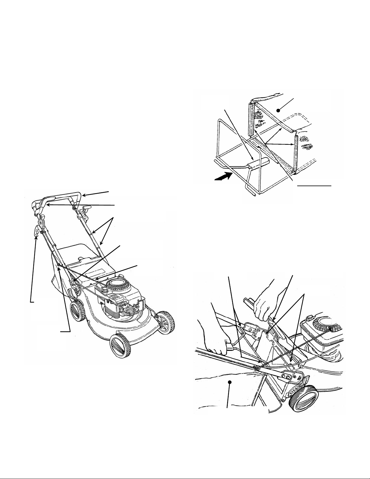
STEP 1: Remove unit from carton and unfold han dle. Do
this carefully to prevent cables from hanging up or
becoming kinked. It will be necessary to remove
cardboard isolators between the handles and knobs.
Tighten Handle Knobs securely. See Figure 1.
STEP 2: Hold bla de control bail down and at t he same
time, pull engine r ope ha ndle and wrap pull c or d into rope
guides that are located on handles. See Figure 1.
STEP 3: Tip mower back agains t the upper h andle to gain
access to cutting blade. Remove foam shipping block
from cutting blade. T his must be removed bef ore starting
the engine.
BLADE CONTROL
CABLE CLIPS
BOLTS
ROPE
HANDLE
THE WAY INTO
GRASS CATCHER
FIGURE 2
STEP 5: Install grass catcher to mower as follows: Lift
discharge door, then grasp handle and hold grass
catcher/fram e up while plac ing rod ends over tabs at rear
of mower deck. Release discharge door. See Figure 3.
ENDS
GRASS
CATCHER
ATTACH STRIPS TO
FRAME.
DISCHARGE DOOR
ROPE
GUIDE
ROPE
GUIDE
FIGURE 1
IMPORTANT: This mower is shipped with the recycling plug
installed. The plug must be removed if the mower is operated
with grass catcher. DO NOT start or operate this mower
without the plug or the entire grass catcher in place.
STEP 4: With grass catcher and catcher frame assembly
upside down (plastic bottom turned up), insert bag frame
assembly into catcher as shown in Figure 2. Fasten "C"
shaped plastic edge strip located on front of bag around
frame assembly on all four sides. Make sure edge strip is
fastened securely.
TABS
GRASS CATCHER
FIGURE 3
INSTRUCTION No. 7-3088 (REV. 1, 8/24/01)
Page 2
2
WARNING
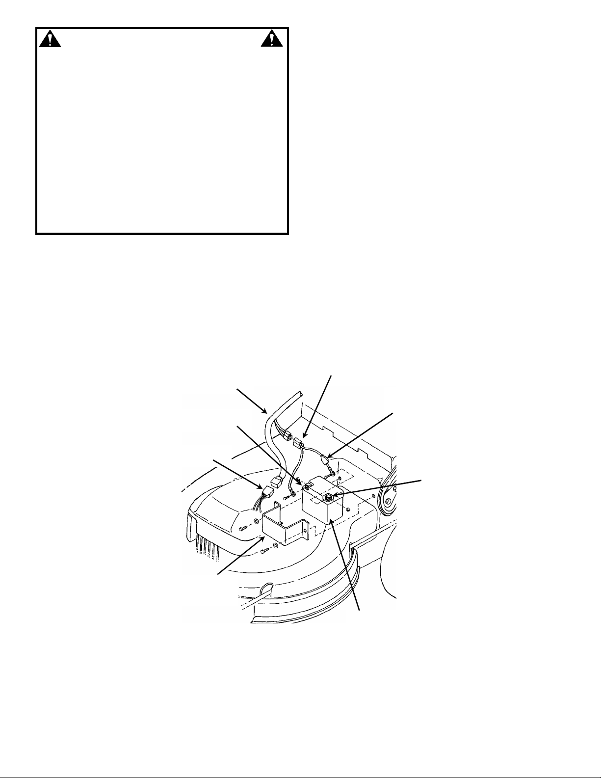
BATTERY
POSITIVE
TERMINAL
BATTERY
DO NOT over fill battery with electrolyte. Shield the
positive terminal with terminal cover located on
battery harness. This prevents metal from touching
the positive terminal which could cause sparks. The
electrolyte (acid) produces a highly explosive gas.
Keep all spa rks, flame and fire awa y from area when
charging battery or when handling electrolyte or
battery. Electrolyte (acid) is a highly cor rosive liquid.
Wear eye pro t e cti o n. Wash affec t ed a r ea s immediatel y
after having e ye or skin c onta ct with el ectro lyte (a cid ).
Battery acid i s corro sive. Rinse emp ty aci d cont aine rs
with water and mutilate before discarding. If acid is
spilled on battery, bench, or clothing, etc., Flush with
clear water and neut ralize with baking soda. DO NOT
attempt to charge battery while installed on the walk
behind. DO NOT use “BOOST” chargers on the
battery.
STEP 6: ACTIVATING AND CHARGING BATTERY
Electric st art models are s hipped wit h a Battery Ki t. The
kit includes a dry charged battery, hardware, harness,
battery charger, electrolyte (acid) and instructions.
The battery requires activation and charging prior to
being installed on the mower. The electrolyte is a very
dangerous, corrosive and poisonous liquid. Follow very
carefully, all instructions and warnings provided with the
kit.
ENGINE HARNESS
MAIN HARNESS
NEGATIVE TERMIN AL
BRACKET
FIGURE 4
IMPORTANT: Only use battery charger provided with the
kit to charge battery.
1. Remove battery from carton .
2. Place batter y in a well ven tilate d area o n a leve l non-
concrete surface.
3. Remove sealing tape from top of battery, exposing
cells.
4. Prepare e lectrol yte and fi ll cells , followi ng instr uctions
provided with the electrolyte.
5. Install strip of battery plugs making sure that each
plug is fully seated and each cell is sealed.
6. Slow charge batt er y for a m in imum of 18 hours us ing
charger provided with kit, being careful to observe
correct charger and battery polarity.
7. Loosen bolts that secure battery bracket to deck.
Slide batt ery into battery bracket. T ighten bracket bo lts
securely. See Figure 4.
8. Connect battery harness to main harness. See
Figure 4.
HARNESS
COVER
TERMINAL
BATTERY
Page 3

3
DEALER PRE-SALE CHECKLIST for SNAPPER 21" CAST ALUMINUM
REAR DISCHARGE WALK BEHIND MOWERS
The following must b e accomplished prior to sale. Refer to the previo us pages in this instruction fo r detailed
set-up instructions. Revi ew this checklist with purchaser. Ch eck (
checklist.
SET-UP CHECKLIST
_____ FOAM SHIPPING BLOCK removed from cutting blade.
_____ UPPER HANDLE & LOWER HANDLE secured in place and hardware tightened securely.
_____ SIDE CHUTE, RECYCLING PLUG or GRASS CATCHER installed on mower.
_____ BLADE retaining bolt(s) checked and tighten securely.
_____ BATTERY, electrolyte added to proper level, charged and installed. All cables connected (Electric Start Models).
LUBRICATION
_____ ENGINE OIL added to bring level up to full mark on 4-cycle engines (Refer to Engine Manual).
_____ OIL mixed with FUEL in specified ratio (2 Cycle Engines Only).
OPERATIONAL TEST
_____ ENGINE started, engine control settings checked and adjusted as needed.
_____ WHEEL DRIVE checked for proper operation and adjusted as needed (Self-Propelled Models).
_____ GROUND SPEED control checked (Self-Propelled Models).
CPSC (Consumer Product Safety Commission) COMPLIANCE TEST
_____ BLADE CONTROL stops engine when released.
DEALER’S RECORDS & FINAL CHECK
_____ PERSONALLY HANDED Operator’s Manual & Mower Safety Booklet to purchaser.
_____ INSTRUCTED purchaser to read and follow instructions in Operator’s Manual.
_____ DEMONSTRATED proper starting procedure and operation of mower to purchaser.
_____ INSTRUCTED purchaser how to service air cleaner, maintain oil level (4-cycle), or mix oil (2-cycle).
_____ ASSISTED purchaser in completing Product Registration Card.
CONSUMER/OPERATOR PRODUCT REGISTRATION CARD
Purchase Date ___________________ Model ________________________ Serial No._________________________
Retailers Name ___________________________________ Signature ______________________________________
Address _____________________________________ City _____________________State ________ Zip ________
MOWER WILL BE USED COMMERCIALLY? _______YES______ NO
Purchaser’s Name _________________________________ Signature _____________________________________
Address ____________________________________ City ______________________State ________Zip ________
IMPORTANT: This form is to be retained by the Dealer for future reference regarding Warranty, proof of
purchase, traceability for product recall or service, etc. Complete the Product Registration Card and Mail to
Customer Service Department at SNAPPER, P.O. BOX 1379, McDonough, Georgia, 30253.
✓) items actually performed and signed on
INSTRUCTION No. 7-3088 (I.R. 9/17/99)
 Loading...