

Page 1
DEALER SET-UP INSTRUCTIONS for EUROPEAN SNAPPER
MOWER SHOWN AS REMOVED FROM SHIPPING
MODEL SHOWN)
UPPER
UPPER
LOWER
LOWER
LOWER
UPPER HANDLE &
LOWER
21” STEEL DECK “M” MODEL WALK BEHIND MOWERS
This SNAPPER Walk Behind Mower uses a handle engine control bail s ystem to kill th e engine for the SAFETY of
the operator. These mowers are designed for quick set-up. T he checklist on Page 4 should be filled out by the
dealer as the items are checked off and/or performed and the Consumer/Operator Product Regist rati on card filled
out and sent to the Customer Serv ice department at SNAPPER when completed . CAUTION: Cutting blades are
extremely sharp. We ar heavy leather gloves when handling or working with blades. Be careful to avoid cutting
yourself on sharp edges of blade.
PUSH MODELS
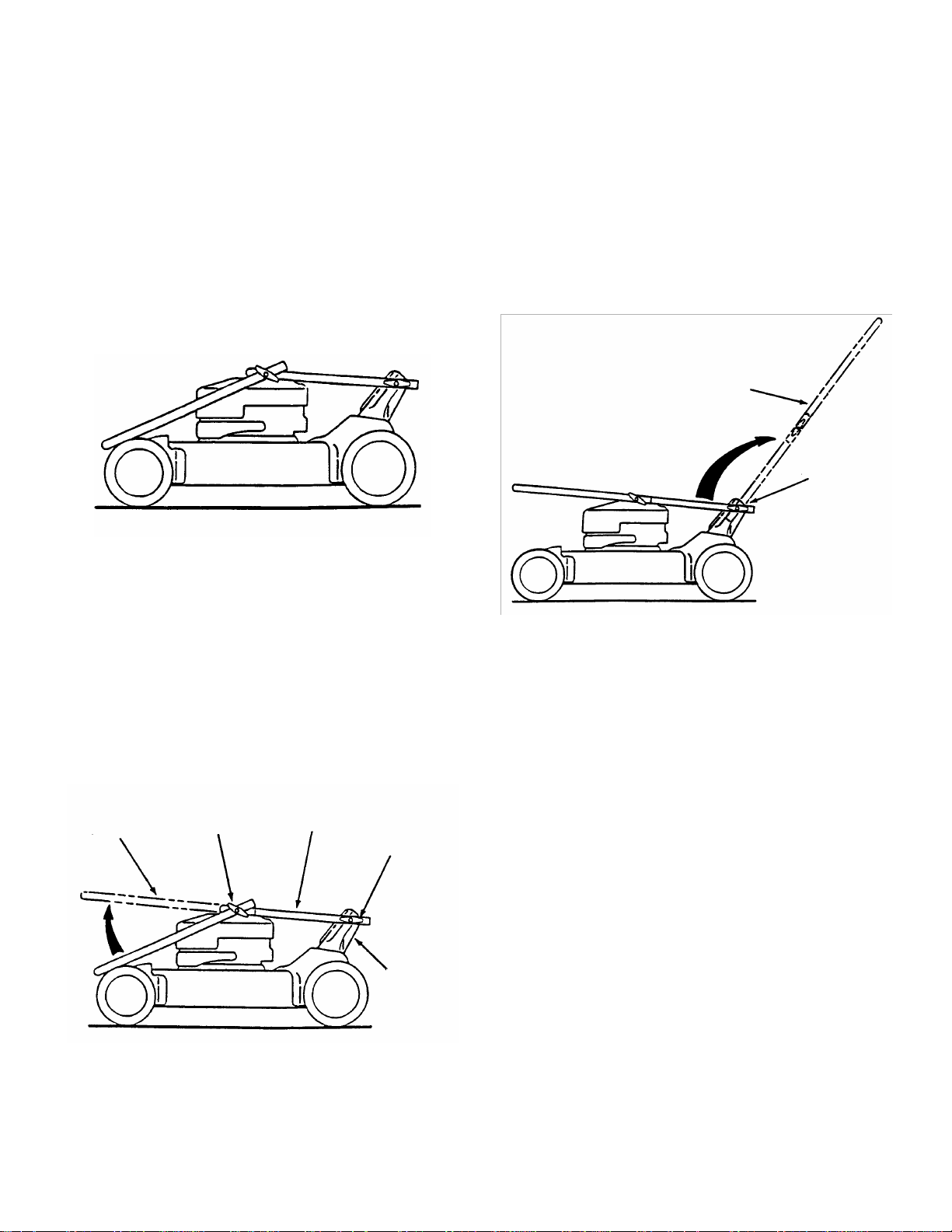
STEP 1: Remove mower from shipping carton. Mower
shown as removed from shipping carton with handles
folded in Figure 1.
STEP 3: Raise upper an d lower handle until i t seats into
position in the lower handle brackets. Securely tighten
lower handle T-Knobs on both sides. See Figure 3.
LOWER HANDLE
SHOWN IN POSITION
HANDLE
T-KNOB
CARTON WITH HANDLES FOLDED (PUSH
FIGURE 1
STEP 2: Remove and dis c ard c ardboard from between all
handles. Raise upper handle until it is in line and seats
into lower handle. Securel y tighten upper handle T -Knobs
on both sides. See Figure 2.
HANDLE
HANDLE
T-KNOB
HANDLE
HANDLE
T-KNOB
HANDLE
BRACKET
FIGURE 2
FIGURE 3
IMPORTANT: DO NOT tip machine with carburetor or
spark plug down. Oil fr om crankcase will saturate the air
filter and cause the engi ne to be hard to start or not start
at all. If contaminatio n does oc c ur , the air filter will have to
be replaced.
IMPORTANT: DO NOT tip machine with carburetor or
spark plug down. Oil fr om crankcase will saturate the air
filter and cause the engi ne to be hard to start or not start
at all. If contaminatio n does oc c ur , the air filter will have to
be replaced.
STEP 4: Tip mower back against the upper handle to gain
access to cutting blade. Remove foam shipping block
from cutting blade. T his must be removed before star ting
the engine.
INSTRUCTION No. 7-3133 (REV 1, 2/12/01)
Page 2
2
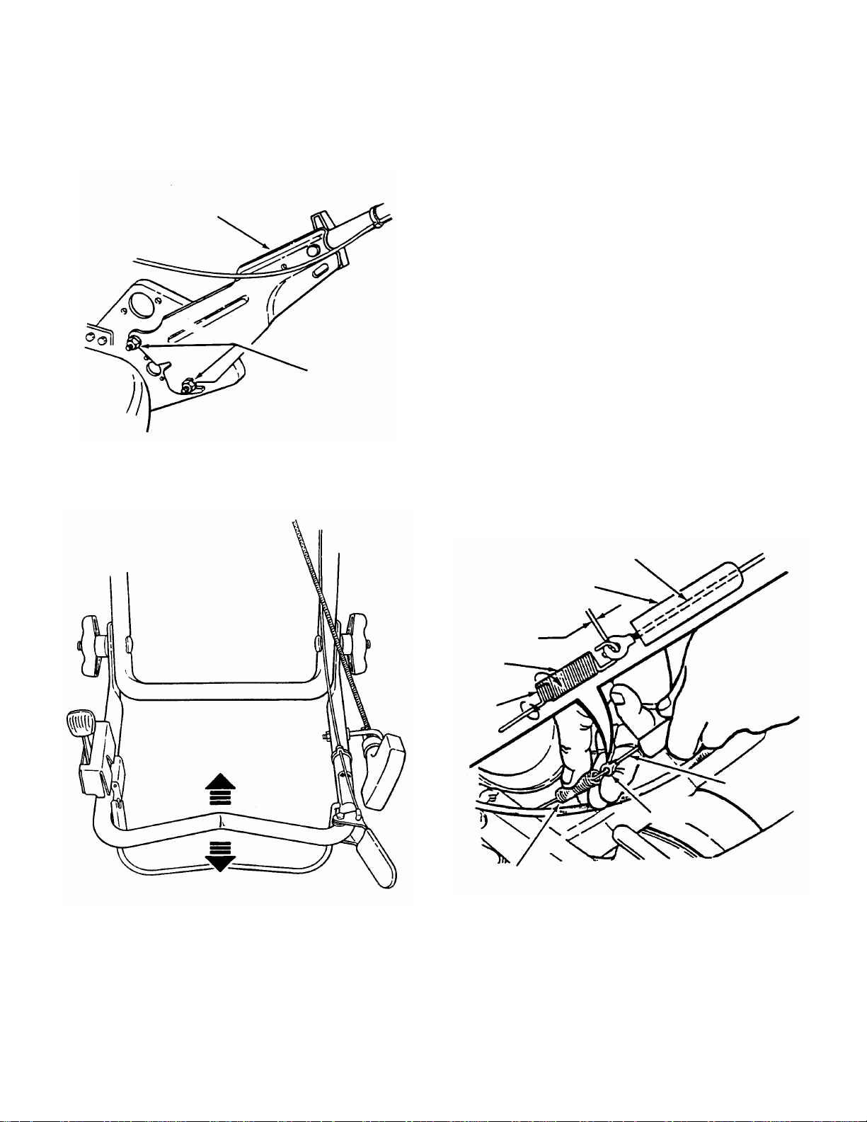
STEP 5: Handle hei ght is adjus table f or dif ferent hei ght of
LOWER HANDLE
LOOSEN
MOVE UPPER HANDLE
1/16”
-
1/8”
CLEARANCE
OUTER
INNER
SPRING
CLUTCH
operators. Loosen the two nuts on the inside of each of
the lower handles. S ee Figure 4. Move the hand le up or
down to the desired height. See Figure 5. Retighten all
nuts securely after adjus tment. Pull blade control agains t
upper handle, pull rope start handle and loop into rope
guide. See Figure 5.
BRACKET
TWO NUTS
FIGURE 4
STEP 6: Set-up is now complete for push models
without self-propelled drive system. For self-propelled
models continue to the “Self-Propelle d Models” Sectio n.
Proceed to the pre-s ale ch ecklist page of this i nstruction
to prepare the mower for use.
SELF-PROPELLED MODELS
NOTE: The set-up procedure for self-propelled models is
basically the same as the Push Models. Follow the exact
procedure as described in Steps 1 thru 6 from the Push
Models section.
STEP 7: Check the cleara nce between the clutch cable
and clutch spring. NOTE: Clearanc e betwee n spring and
cable is very im portant. Excessive clearance will c ause
drive system NOT to oper ate when wheel drive control
handle is depressed. No clearance at all will cause
mower to continue to propel itself when wheel drive
control handle is released to stop mower movement.
Slide vinyl spring cover (located at the end of clutch
cable) up clutch cable to gain access to the end of spring
and cable loop. With wheel drive control handle
released, clearanc e bet ween spri ng hook and cab le loop
should be 1/16” to 1/8”. If cleara nce is m ore or less than
specified, unhook spring from clutch cable eye, then
adjust by rotating outer spring clockwise or counter
clockwise to achieve the proper clearance. Rehook
spring to clutch cable eye. Slide vinyl cover over the
spring when correct clearance is reached. See Figure 6.
CLUTCH CABLE
VINYL SPRING COVER
SPRING
UP OR DOWN FOR
PROPER HEIGHT
CABLE
CABLE EYE
SPRINGS
FIGURE 5
FIGURE 6
Page 3

3
STEP 8: Driven d isc to driv e disc adjustment is set up at
MOVE GROUND SPEED
SIXTH SPEED
FIRST SPEED
DRIVEN DISC
DRIVEN
TRANSFER
CONNECTOR HEX
1/8” MEASUREMENT
SLIDE DRIVEN
TRANSFER
CONNECTOR
OUTSIDE
DRIVE
the factory. In case driven disc may need adjustment,
proceed as follows:
A. Place s peed control rod in the num ber six speed
position. See Figure 7.
POSITION
CONTROL TO SIX SPEED
POSITION
SIXTH
POSITION
C. Slide driven disc assembly over until 1/8” from
outside edge of drive disc. Maintaining the 1/8”
measurement, remove any looseness from the linkage.
This can be done by holding the transfer rod and
applying pressure to the left (as viewed from operators
position), then retighten the connector hex nut
securel y. See Figure 9. Move shift ro d to the number
one speed pos i ti o n, t h en ba c k to the number s ix s p ee d
position. Recheck the 1/8” measurement described
previously. Reinstall driven disc spring to driven disc
assembly.
TO OUTSIDE EDGE
DISC ASSEMBLY
TOWARD
OUTSIDE EDGE
OF DRIVE DISC
DISC
FIRST
FIGURE 7
B. Remove driven disc spring from driven disc
assembly as shown. Lo osen c onnector hex- nut. See
Figure 8.
ASSEMBLY
DRIVE DISC
DISC
SPRING
ROD
NUT
CONNECTOR
FIGURE 8
CONNECTOR
ROD
HEX NUT
FIGURE 9
STEP 9: Make sure all nuts and bolts are tight. Set-up is
now complete for self-propelled models Proceed to t he
pre-sale checklist page of this instruction to prepare
mower for use.
EDGE
Page 4

4
DEALER PRE SALE CHECKLIST for SNAPPER
21” STEEL DECK “M” MODEL WALK BEHIND MOWERS
The following must b e accomplished prior to sale. Refer to the previo us pages in this instruction fo r detailed
set-up instructions. Revi ew this checklist with purchaser. Ch eck (
checklist.
SET-UP CHECKLIST
_____ FOAM SHIPPING BLOCK removed from cutting blade.
_____ UPPER HANDLE & LOWER HANDLE secured in place and hardware tightened securely.
_____ SIDE CHUTE, RECYCLING COVER or GRASS BAG installed on mower.
_____ BLADE retaining bolt(s) checked and tighten securely.
LUBRICATION
_____ ENGINE OIL added to bring level up to full mark on 4-cycle engines (Refer to Engine Manual).
_____ DIFFERENTIAL grease checked and added if needed.
OPERATIONAL TEST
_____ ENGINE started, engine control settings checked and adjusted as needed.
_____ WHEEL DRIVE checked for proper operation and adjusted as needed (Self-Propelled Models).
_____ DRIVE DISC adjustment checked and made (Self-Propelled Models).
_____ GROUND SPEED control checked (Self-Propelled Models).
CPSC (Consumer Product Safety Commission) COMPLIANCE TEST
_____ BLADE CONTROL stops engine when released.
DEALER’S RECORDS & FINAL CHECK
_____ PERSONALLY HANDED Operator’s Manual & Mower Safety Booklet to purchaser.
_____ INSTRUCTED purchaser to read and follow instructions in Operator’s Manual.
_____ DEMONSTRATED proper starting procedure and operation of mower to purchaser.
_____ INSTRUCTED purchaser how to service air cleaner, maintain oil level (4-cycle).
_____ ASSISTED purchaser in completing Product Registration Card.
CONSUMER/OPERATOR PRODUCT REGISTRATION CARD
Purchase Date ___________________ Model _______________________ Serial No.________________________
Retailers Name ___________________________________ Signature _____________________________________
Address _____________________________________ City ____________________ State _______ Zip _______
MOWER WILL BE USED COMMERCIALLY? _______ YES _____ NO
Purchaser’s Name _________________________________ Signature ____________________________________
Address ____________________________________ City _____________________ State _______ Zip _______
IMPORTANT: This form is to be retained by the Dealer for future reference regarding Warranty, proof of
purchase, traceability for product recall or service, etc. Complete the Product Registration Card and Mail to
Customer Service Department at SNAPPER, P.O. BOX 1379, McDonough, Georgia, 30253.
✓) items actually performed and signed on
INSTRUCTION No. 7-3133 (REV 1, 2/12/01)
 Loading...