

Snapper W48120, W48120K, W48140S, W36120, W36120K Assembly Instructions Operator's Manual
...Assembly Instructions & Operator's Manual for

MODEL NUMBERS: W32080 W32120 W32120K
W36120 W36120K
W48120 W48120K W48140S

32", 36", & 48" COMMERCIAL MOWERS

(12/87) Manual # 05119
IMPORTANT SAFETY INSTRUCTIONS
WARNING: Failure to comply with the following instructions may result in serious injury to the operator or other persons. The owner of the mower must understand these instructions and, furthermore, must allow only persons who understand these instructions to operate the mower. Each person operating the mower must be of sound mind and body and must not be under the influence of any substance which might impair vision, dexterity, or judgment. If you have any questions pertaining to your mower which your dealer cannot answer to your satisfaction, call or write the Customer Service Department at SNAPPER POWER EQUIPMENT, McDonough Georgia, 30253 (Phone 404-957-9141).
TRAINING
- 1. Read this Manual carefully and question your dealer if something is not clear. Should the dealer be unavailable or unable to answer to your satisfaction, write or call our Customer Service Department at the factory. Be thoroughy familiar with the controls and proper use of the equipment.
- 2. DO NOT allow children in yard when mower is operated.
- 3. DO NOT allow pre-teenage children to operate mower.
- 4. Allow only responsible teenagers with mature judgment to operate mower and only under close supervision.
- 5. Keep the area clear of all persons, particularly small children, and pets.
PREPARATION
- 1. Never operate mower without proper guards, plates, safety switches, or other safety protective devices in place and properly connected. Inspect to determine that these safety devices are installed properly, are in good repair, and operate properly. If the condition or operation of these devices are questionable, they must be repaired or replaced before using the mower.
- 2. Thoroughly inspect the area where the mower is to be used and remove all stones, sticks, wire, bones and other foreign objects. Also note the location of holes, stumps, and other possible hazards.
- 3. Do not operate mower when barefoot or wearing open sandals. Always wear substantial footwear and long pants.
- 4. Fill gasoline tank before starting engine. Use approved gasoline container. Do not smoke near open gasoline container. Do not fill gasoline tank indoors or when engine is running. Allow engine to cool for at least ten minutes before refilling. Wipe off any spilled gasoline before starting engine. Do not run engine indoors.
- 5. Lock both drive levers into NEUTRAL LOCK position before starting engine.
- 6. Never attempt to make a wheel height adjustment while engine is running.
- 7. When mowing over rough ground or in tall grass, mower must be set in highest cutting position.
- 8. Mow only in daylight or in good artificial light.
- 9. Never operate mower in wet grass. Always be sure of your footing; keep a firm hold on the handle and walk, never run.
OPERATION
- 1. Do not change engine governor settings or overspeed engine.
- 2. Do not put hands or feet near or under rotating parts. Keep clear of discharge area while engine is running.
- 3. Disengage blade drive when crossing gravel drives, walks, or roads, and under any conditions where thrown objects might be a hazard.
- 4. After striking a foreign object or if mower vibrates abnormally, stop the engine, disconnect and secure spark plug wire. Inspect the mower for any damage and repair the damage.
- 5. Stop engine whenever you leave the operating position behind the handle for any reason, including emptying grass catcher and making any adjustments, repairs, or inspections.
- 6. Before cleaning, repairing or inspecting, make certain blade and all moving parts have stopped. Disconnect and secure spark plug wire away from plug to prevent accidental starting.
- Stop engine and wait until the blade comes to complete stop before removing grass catcher and/ or unclogging adapter.
- 8. Mow across slopes, never up-and-down. Exercise caution when changing directions on slopes. Do not mow steep slopes.
- 9. When parking mower, stop engine and leave drive levers in DRIVE position.
- 10. Do not use sulky on slopes.
MAINTENANCE AND STORAGE
- 1. Keep all nuts, bolts, and screws tight to be sure mower is in safe operating condition.
- 2. Never store mower with gasoline in the tank inside of a building where fumes may reach an open flame or spark. Allow engine to cool before storing in any enclosure.
- 3. To reduce fire hazard, keep mower free of grass, leaves, or excessive grease.
- 4. Check grass catcher assembly frequently for wear or deterioration. Replace with new bag if loose seams or tears are evident.
- 5. Have your mower inspected and serviced each year by an authorized Snapper dealer. Determine if any additional devices are available which might upgrade the safety of your mower.
- 6. Factory specified Snapper replacement parts must be used to assure adequate protection against injury.
Symbols like the one shown at left are used to call your attention to specific safety information in the text. This information deserves your careful attention and understanding. Failure to understand or comply with safety related information may result in injury to you or others.
.
CONTENTS
| ower Assembly | 8 |
|---|---|
| eration | 0 |
| justments | 9 |
| Belts | 5 |
|
A. Belt Kouting1
B. Belt Tension 1 |
5
0 |
| C. Guides and Snubbers |
0
9 |
| Brake/Propel Mechanism 1 | 4 |
| Brake Tension | 5 |
| Î |
| Cutting Height |
|
11 |
|---|---|---|
| Drivewheel Scrapers |
|
19 |
| Interlock Switches |
|
15 |
| ervice |
|
20 |
| Cutting Blades |
|
20 |
| Worm Gear Reduction Box |
|
20 |
| Maintenance Chart |
|
23 |
| Hardware Torque Specifications |
|
23 |
| Troubleshooting |
|
22 |
Warning or operating decals that become damaged or illegible should be replaced immediately.
| Decal Kits: | ||||
|---|---|---|---|---|
| 32" m | iowers . |
|
|
Part No. 771 |
| 36" m | lowers . |
|
|
Part No. 772 |
| 48" | mowers | . Part No. 77367 |
|---|---|---|
| 48" | mower (14 H.P.) | Part No. 77375 |
MOWER ASSEMBLY
This section describes recommended assembly procedures for mowers as shipped from the factory. Once initial assembly is complete, refer to pages 11-19 for final adjustments.
Note: If your mower has already been assembled and adjusted by your authorized Snapper Dealer, move directly to "Pre-operation Service" (Pg. 7).
Inspect mower mainframe and all loose parts for signs of damage before proceeding with assembly. Contact your Snapper dealer if damage is noted.
Mowers already removed from the shipping pallet must be propped up from the floor to allow clearance for front wheel attachment. Use the 2" x 4" x 7" blocks attached to the pallet for this purpose.
Refer to the Torque Specifications on Page 23 for correct hardware installation figures.
Note: Use of a pneumatic wrench is not recommended for Nyloc nuts. High speed installation can damage locking capability.
Step #1 Front Wheel Attachment
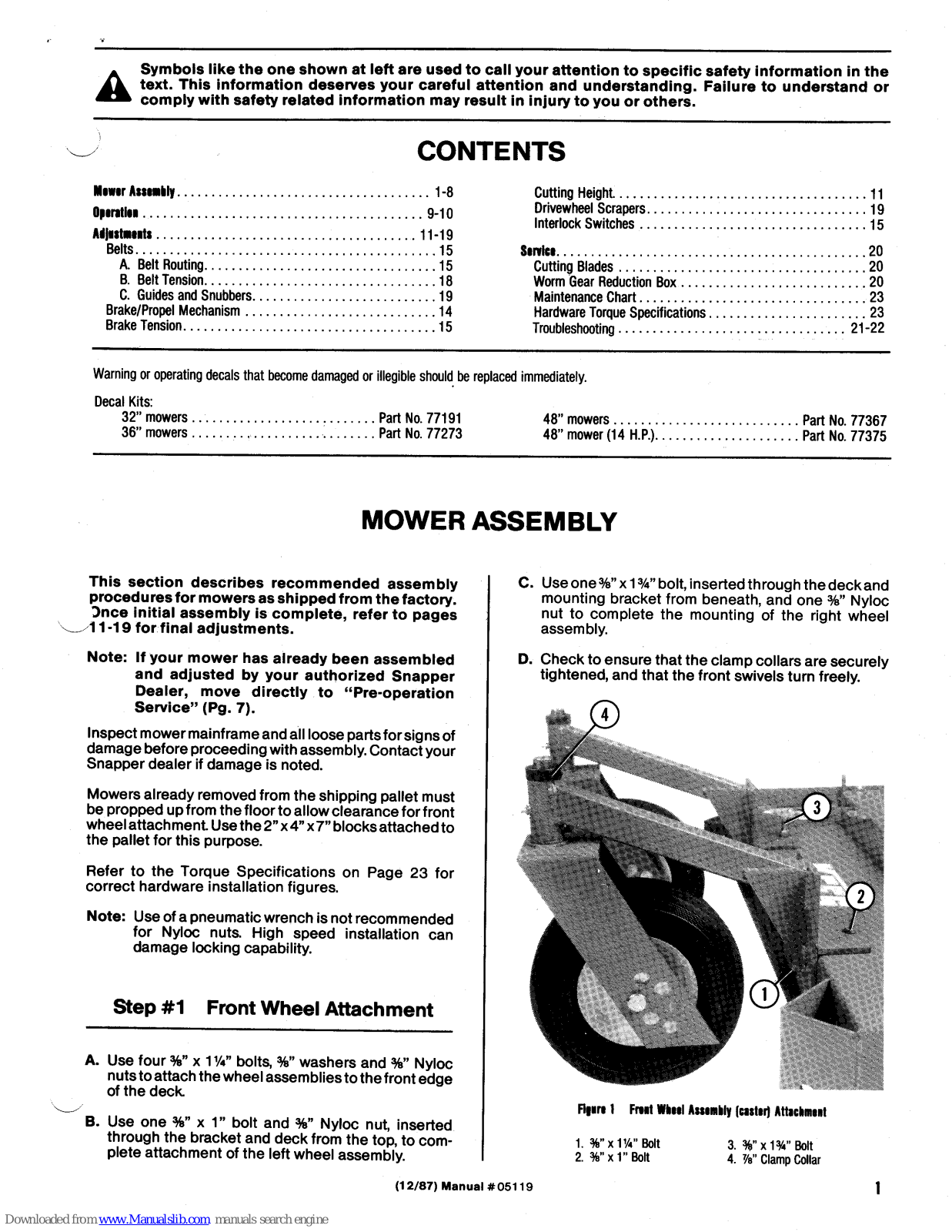
- A. Use four %" x 1¼" bolts, %" washers and %" Nyloc nuts to attach the wheel assemblies to the front edge of the deck.
- B. Use one %" x 1" bolt and %" Nyloc nut, inserted through the bracket and deck from the top, to complete attachment of the left wheel assembly.
- C. Use one %" x 1 %" bolt, inserted through the deck and mounting bracket from beneath, and one %" Nyloc nut to complete the mounting of the right wheel assembly.
- D. Check to ensure that the clamp collars are securely tightened, and that the front swivels turn freely.

Figure 1 Front Wheel Assembly (caster) Attachment
| %" | x 1¼" Bolt | 3. | 3%)" | x 1¾" | Bolt |
|---|---|---|---|---|---|
| %" | x 1" Bolt | 4. | 7⁄8" | Clamp | Colla |
2
- A. Position tank onto mounting bracket.
- B. Position the short tank band across the rear of the tank, over the tank pads at the level of the mounting slots. Thread the end of the band through both slots until the end can be inserted into the screw portion of the band, centered at the back of the tank. Snug the band down, but do not tighten it until the other band has been attached.
Note: For Model W48140S. omit Step C.
- C. Position the long tank band across the top of the tank, over the tank pads. Run it through both mounting slots and insert the end into the screw portion of the band, centered on top of the tank. Tighten both bands to secure the tank.
- Note: Do not overtighten. Excessive tightening may distort tank.

Figure 2 Fuel Tank Attachment
1. Short Tank Band 2. Long Tank Band 3. Gas Tank Pads

A. Route fuel line from gas tank through nylon tie on lower handle and connect it to fuel filter, using gas line hose clamp provided. Tighten nylon tie to prevent gas line from contacting worm gear reduction box.
Note: A fuel shut-off is provided at the tank outlet and at the carburetor inlet. Check to be sure both are open for operation.

Figure 3 Fuel Line
| 1. | Nylon Tie | 3. | Tank Shut-off |
|---|---|---|---|
| 2. | Fuel Filter | 4. | Worm Gear Reduction Box |
Step #4 Muffler Installation
Note: For Model W48140S, omit all of Step #4.
- Briggs & Stratton 12 h.p. Engines:
- A. Loosely preassemble the bracket and clamp to the muffler as shown in Figure 4. The bracket should move freely on the muffler.

2. Clamp
3. ¼" x %" Bolt and ¼' Lockwasher
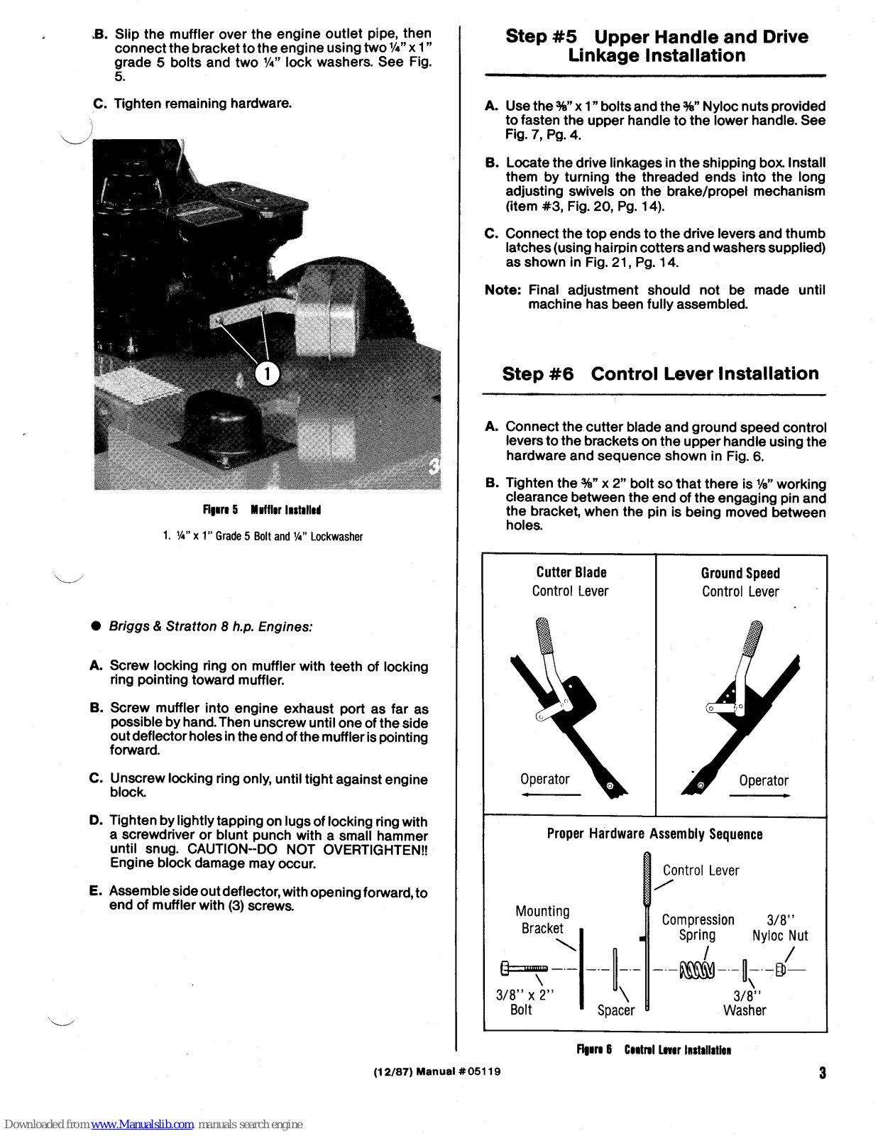
- .B. Slip the muffler over the engine outlet pipe, then connect the bracket to the engine using two ¼" x 1" grade 5 bolts and two ¼" lock washers. See Fig. 5
- C. Tighten remaining hardware.

Figure 5 Muffler Installed
1. ¼" x 1" Grade 5 Bolt and ¼" Lockwasher
- Briggs & Stratton 8 h.p. Engines:
- A. Screw locking ring on muffler with teeth of locking ring pointing toward muffler.
- B. Screw muffler into engine exhaust port as far as possible by hand. Then unscrew until one of the side out deflector holes in the end of the muffler is pointing forward.
- C. Unscrew locking ring only, until tight against engine block.
- D. Tighten by lightly tapping on lugs of locking ring with a screwdriver or blunt punch with a small hammer until snug. CAUTION--DO NOT OVERTIGHTEN!! Engine block damage may occur.
- E. Assemble side out deflector, with opening forward, to end of muffler with (3) screws.
Step #5 Upper Handle and Drive Linkage Installation
- A. Use the %" x 1" bolts and the %" Nyloc nuts provided to fasten the upper handle to the lower handle. See Fig. 7, Pg. 4.
- B. Locate the drive linkages in the shipping box. Install them by turning the threaded ends into the long adjusting swivels on the brake/propel mechanism (item #3, Fig. 20, Pg. 14).
- C. Connect the top ends to the drive levers and thumb latches (using hairpin cotters and washers supplied) as shown in Fig. 21, Pg. 14.
- Note: Final adjustment should not be made until machine has been fully assembled.
Step #6 Control Lever Installation
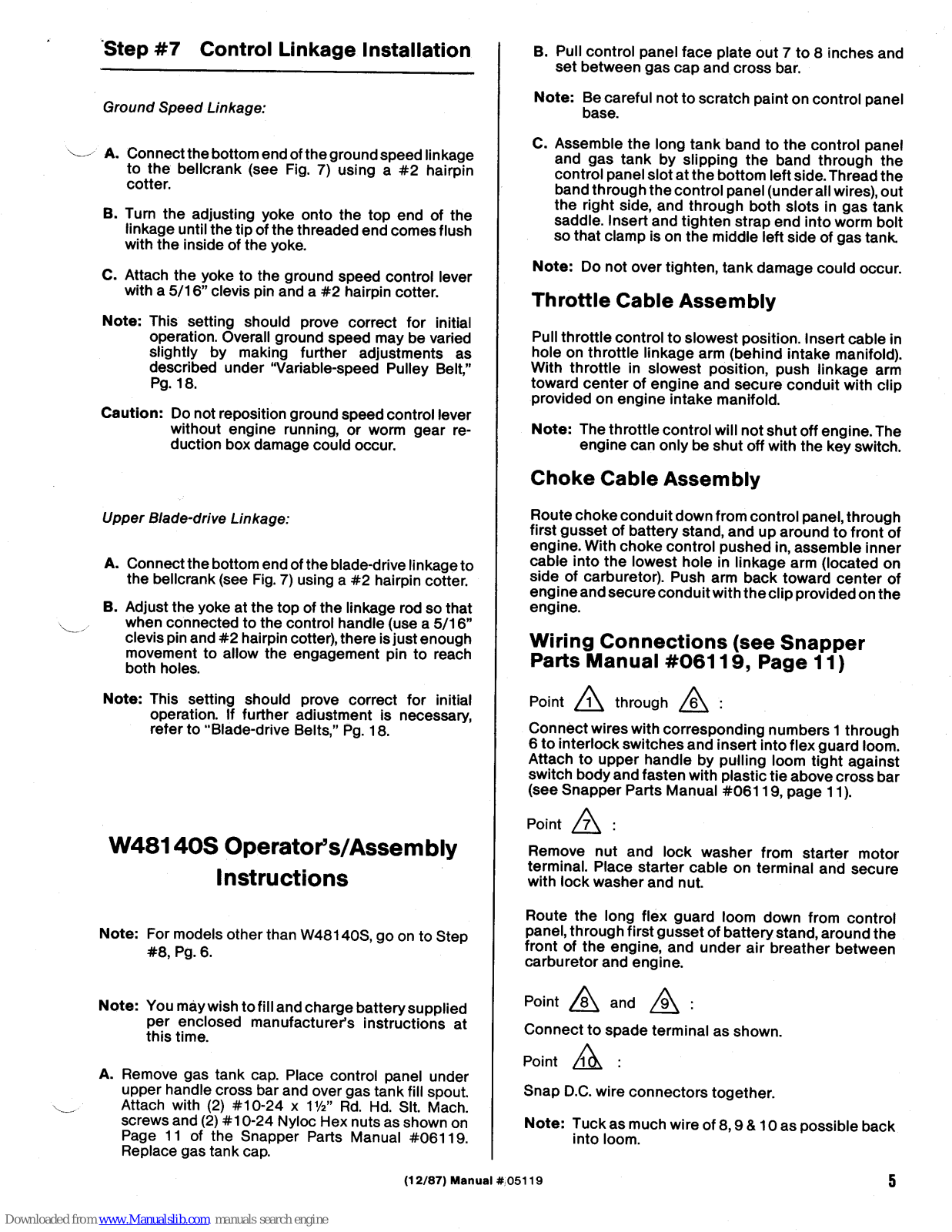
- A. Connect the cutter blade and ground speed control levers to the brackets on the upper handle using the hardware and sequence shown in Fig. 6.
- B. Tighten the %" x 2" bolt so that there is %" working clearance between the end of the engaging pin and the bracket, when the pin is being moved between holes.

Proper Hardware Assembly Sequence

Figure 6 Control Lover Installation
(12/87) Manual #05119

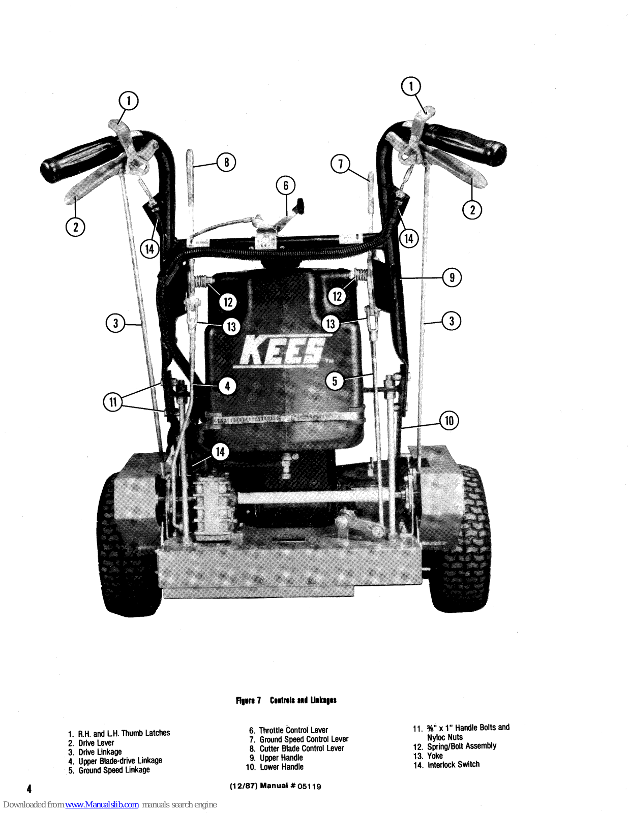
Figure 7 Controls and Linkages
- 1. R.H. and L.H. Thumb Latches
- 2. Drive Lever 3. Drive Linkage 4. Upper Blade-drive Linkage 5. Ground Speed Linkage
- 6. Throttle Control Lever 7. Ground Speed Control Lever 8. Cutter Blade Control Lever
- Upper Handle
- 10. Lower Handle
- (12/87) Manual # 05119
-
11. %" x 1" Handle Bolts and Nyloc Nuts
- 12. Spring/Bolt Assembly 13. Yoke 14. Interlock Switch
4
Step #7 Control Linkage Installation
Ground Speed Linkage:
-
A. Connect the bottom end of the ground speed linkage to the bellcrank (see Fig. 7) using a #2 hairpin cotter.
- B. Turn the adjusting yoke onto the top end of the linkage until the tip of the threaded end comes flush with the inside of the voke.
- C. Attach the yoke to the ground speed control lever with a 5/16" clevis pin and a #2 hairpin cotter.
- Note: This setting should prove correct for initial operation. Overall ground speed may be varied slightly by making further adjustments as described under "Variable-speed Pulley Belt," Pg. 18.
- Caution: Do not reposition ground speed control lever without engine running, or worm gear reduction box damage could occur.
Upper Blade-drive Linkage:
- A. Connect the bottom end of the blade-drive linkage to the bellcrank (see Fig. 7) using a #2 hairpin cotter.
- B. Adjust the yoke at the top of the linkage rod so that when connected to the control handle (use a 5/16" clevis pin and #2 hairpin cotter), there is just enough movement to allow the engagement pin to reach both holes.
- Note: This setting should prove correct for initial operation. If further adjustment is necessary, refer to "Blade-drive Belts," Pg. 18.
W48140S Operator's/Assembly Instructions
- Note: For models other than W48140S, go on to Step #8, Pg. 6.
- Note: You may wish to fill and charge battery supplied per enclosed manufacturer's instructions at this time.
- A. Remove gas tank cap. Place control panel under upper handle cross bar and over gas tank fill spout. Attach with (2) #10-24 x 1½" Rd. Hd. Slt. Mach. screws and (2) #10-24 Nyloc Hex nuts as shown on Page 11 of the Snapper Parts Manual #06119. Replace gas tank cap.
- B. Pull control panel face plate out 7 to 8 inches and set between gas cap and cross bar.
- Note: Be careful not to scratch paint on control panel base.
- C. Assemble the long tank band to the control panel and gas tank by slipping the band through the control panel slot at the bottom left side. Thread the band through the control panel (under all wires), out the right side, and through both slots in gas tank saddle. Insert and tighten strap end into worm bolt so that clamp is on the middle left side of gas tank.
Note: Do not over tighten, tank damage could occur.
Throttle Cable Assembly
Pull throttle control to slowest position. Insert cable in hole on throttle linkage arm (behind intake manifold). With throttle in slowest position, push linkage arm toward center of engine and secure conduit with clip provided on engine intake manifold.
Note: The throttle control will not shut off engine. The engine can only be shut off with the key switch.
Choke Cable Assembly
Route choke conduit down from control panel, through first gusset of battery stand, and up around to front of engine. With choke control pushed in, assemble inner cable into the lowest hole in linkage arm (located on side of carburetor). Push arm back toward center of engine and secure conduit with the clip provided on the engine.
Wiring Connections (see Snapper Parts Manual #06119, Page 11)
Point 1 through 6
Connect wires with corresponding numbers 1 through 6 to interlock switches and insert into flex guard loom. Attach to upper handle by pulling loom tight against switch body and fasten with plastic tie above cross bar (see Snapper Parts Manual #06119, page 11).
Point A :
Remove nut and lock washer from starter motor terminal. Place starter cable on terminal and secure with lock washer and nut.
Route the long flex guard loom down from control panel, through first gusset of battery stand, around the front of the engine, and under air breather between carburetor and engine.
Point 8 and 9
Connect to spade terminal as shown.
Point 10 :
Snap D.C. wire connectors together.
Note: Tuck as much wire of 8, 9 & 10 as possible back into loom.
Point AL & A
Connect battery ground cable to negative post on battery with (1) 5/16"-18x3/4" bolt and 5/16"-18 Nyloc Hex nut lise similar hardware for positive cable connection
Continue through Operator's Manual starting with Step #9. excluding Step #11.
Control Identification
Choke Control:
Key Switch:
Positions: "OFF"
- Shuts engine off
- Activates afterfire solenoid (prevents engine backfire)
- Turns off hour meter "RUN"
- Deactivates afterfire colonoid
- Activates hour meter "OTADT"
- (Spring loaded back to run)
- Starts engine
Note: Always turn to off position when not in use.
Hour Meter: Shows amount of time engine has been running
Note: If key is left in the run position when engine is not running, hour meter will continue to run.
Ammeter: Shows amount of current being supplied by the engine to the battery. At full throttle, maximum reading should be approximately 3 amps.
Fuse: Protects engine charging system and instrumentation from possible electrical malfunction.
Trouble Shooting:
Engine won't start
- Weak or dead battery
- Battery not grounded properly
- Choking may be required
- Battery cable disconnected.
- Note: Disconnect positive battery cable from battery post before any service is done within the control panel.
(12/87) Manual #05119
Note: Continue with Step #9, Page 7.
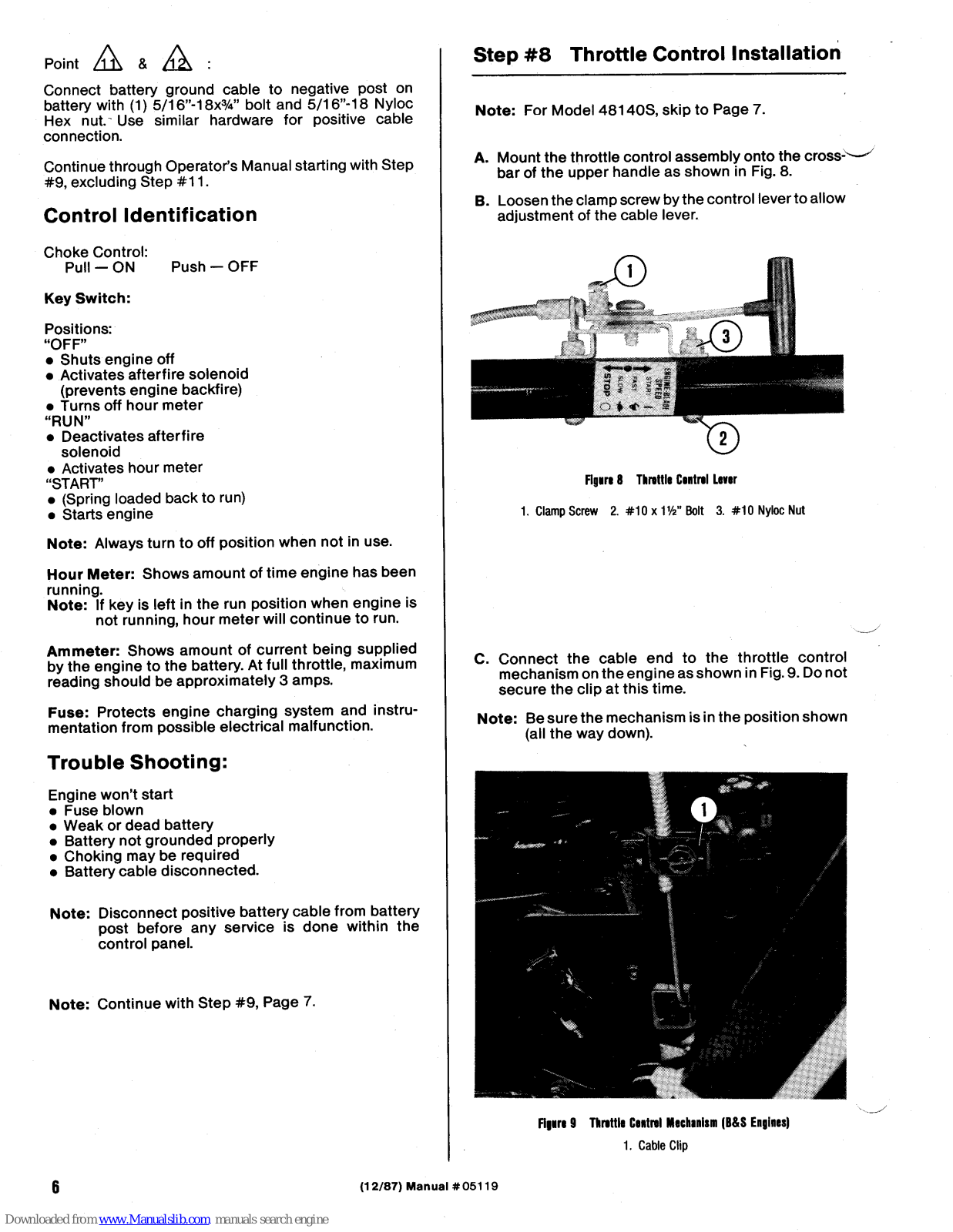
Step #8 Throttle Control Installation
Note: For Model 48140S skip to Page 7.
- A. Mount the throttle control assembly onto the crossbar of the upper handle as shown in Fig. 8.
- B Loosen the clamp screw by the control lever to allow adjustment of the cable lever

Figure 8 Throttle Control Lever
1 Clamp Screw 2 #10 x 116" Bolt 3 #10 Nyloc Nut
- C. Connect the cable end to the throttle control mechanism on the engine as shown in Fig. 9. Do not secure the clip at this time.
- Note: Be sure the mechanism is in the position shown (all the way down)

Figure 9 Throttle Control Mechanism (B&S Engines) 1. Cable Clip
- D. Once connection is made, move the throttle control lever to "Stop" position (B&S), "Slow" position (Kawasaki) and tighten the cable clip and clampscrew.
- E. Move the control back and forth a few times, observing the engine throttle mechanism to insure proper action. Adjust if necessary.
- F. When operation is satisfactory, trim off excess cable wire (at throttle control end) if desired.
Step #9 Belt Shield and Shaft Guard Installation
A. Install and secure belt shield with three 5/16" washers and Nyloc nuts.
Shaft guards are designed to swing away, allowing convenient access to shafts. Nyloc nuts should be left loose enough to allow easy cover movement when hairpin cotter is removed from its retaining pin.
- B. Attach guards with a 5/16" washer and Nyloc nut on threaded stud. Secure in place with a #2 hairpin cotter.
- Note: Position guards with open sides toward operator unless that position will allow exhaust discharge to enter the guard.
Step #10 Discharge Chute Installation
- Note: If Snapper grass catcher is to be used, refer to the instructions supplied with the catcher and install catcher back plate and braces at this time.
- A. Attach discharge chute with two 5/16" x 1" bolts and Nyloc nuts.

Safety Warning: Never operate the mower unless discharge chute or grass catcher is securely in place.
Note: For Model W48140S, skip to Step #12.
Step #11 Interlock Switch Connection
- A. Join the interlock switch wires at the bullet connectors provided (see Fig. 10, Pg. 8, for connector locations). Connect one of the wires from the upper handle with one wire from the interlock switch which is mounted on the lower handle and the other with the male connector from the interlock module (the wires cannot be hooked up wrong, since you are merely completing a circuit).
- B. Connect the remaining wire from the interlock switch on the lower handle to the remaining wire on the interlock module.
- C. Insert the connection into the flex guard loom and reattach the flex guard outlet to the loom.
- D. Hook the activating springs between the interlock switches and the drive levers, as shown in Fig. 21, Pg. 14.
Step #12 Pre-operation Service
- A. Refer to "Adjustments," pages 11-19, for final linkage and cutting height adjustments.
- B. Inspect all mower hardware and fasteners to insure they are properly secured.
- C. Once all final adjustments are made and final cutting height has been set, fill engine crankcase with oil per manufacturer's instructions.
- D. Check rear tire pressures. Fill to 14 PSI.
- Note: Pressure in both tires must be equal to insure straight travel.
- E. Fill fuel tank with fresh gasoline. Consult engine owner's manual for recommended grade.
- Note: Do not use gasoline with ethanol or methanol additives.
- F. Grease fittings on cutter housings, front and rear wheels, front castors, and sulky wheels if applicable.

Safety Warning: Handle gasoline with extreme care. Never allow sparks or flame nearby.

Figure 10 Interlock Switch Wiring
OPERATION

Safety Warning: Be certain you know and understand all control locations and functions Review Safety Instructions in the front of this manual before beginning mower operation.
Control Identification
Throttle Control (Fig. 8)
Move lever as directed to vary engine speed, shut off engine, or prepare engine for starting.
Note: On Kawasaki engines "Start" position auto-matically engages choke. Briggs & Stratton engines must be choked manually
Drive Levers (Fig. 11)

Figure 11 Drive Leve
1. Drive Lever (shown in 2. Handle Grip "Neutral Lock" position) 3 Thumb Latch
The drive levers serve four important functions:
- 1. Stopping forward motion Pull both levers toward the handle grips and hold tightly in place.
- 2. Beginning forward motion Release both levers simultaneously to engage drivewheels.
- 3. Selecting "neutral" position Pull levers partially toward handle grips (drive-
wheels and brakes both disengaged).
To lock drive levers in neutral position, pull back on the thumb latches, then release the levers so they catch as shown in Fig. 11.
4. Steering the mower See "To steer mower," under Operating Procedures (Pg. 10).
Cutter Blade Control (Fig. 12)
Move to start or stop blade rotation

1. Disengage (stop blade rotation) 2. Engage (start blade rotation)
Ground Speed Control (Fig. 17)
Move as desired to change ground speed.
Caution: Change speed only while engine is running to avoid damage to components

1 Slowest 2. Fastest
Operating Procedures
To Begin Operation:
Step #1
- A. Set cutter blade control in the "Stop" position.
- B. Lock both drive levers into "Neutral Lock" position.
- C. Move throttle control to "Start" position.
- Note: Ground speed control should not be repositioned until engine is running. System damage may occur.
- Note: Units with Kawasaki engine, turn "shut-off" switch to "on" position at this time.
Step #2
- A. Pull the recoil handle and start the engine (may require choking).
- B. Once engine has started, move the throttle control to "Slow" position.
- C. Move ground speed control to slowest setting.
Step #3
- A. Engage blades by moving cutter blade control to "Rotate" position.
- B. Move throttle control as necessary to provide desired blade speed.
Step #4
- A. Unlock the drive levers, then slowly release them to begin forward motion.
- B. Move ground speed control to desired setting.
To Steer Mower:
If drive levers are correctly adjusted, mower will travel in a straight line when both levers are released.
To turn, simply squeeze the drive lever on the same side as the direction you wish to turn. This locks the wheel brake on that side and causes the machine to turn.
Continue holding the drive lever until the mower is headed in the desired direction. Release the drive lever and the mower will resume straight-ahead travel.
To Stop Operation:
Emergency Stop
Pull both drive levers firmly toward the handle grips and hold them securely in place.
Use the thumb latches to lock the drive levers in "Neutral Lock" position (see Fig. 11), then move throttle control lever to "Stop" position. Units with Kawasaki engine turn "shut-off" switch to "off" position.
Normal Operating Stop
- A. Pull both drive levers firmly toward the handle grips to stop forward motion.
- B. Use thumb latches to lock the drive levers into "Neutral Lock" position (see Fig. 11).
- C. Move throttle control to "Slow" position.
- D. Move cutter blade control to "Stop" position.
- E. Move ground speed control to slowest setting.
- F. Move throttle control to "Stop" position (B& S only). Units with Kawasaki engine, turn "shut-off" switch to "off" position.
- Note: Close shut-off valve at base of tank following operation.
ADJUSTMENTS

Safety Warning: Shut off engine and disconnect spark plug wire before making any adjustments.
Cutting Height
Your Snapper mower may be set to any of 10 different cutting heights, ranging from 1½" to 5".
It will be necessary to alter the deck height (distance from the bottom edge of the mower deck to the ground)
in order to achieve the desired final cut. This will involve relocation of the rear axle and the front wheels or front wheel assemblies.
Note: Whenever the rear axle has been relocated, you must adjust the brake/propel mechanism and the drivewheel scrapers.
It may also be necessary to relocate the drivewheel scrapers and/or the brake plate swivel.
All of these operations are described following the chart below.
To Change Cutting Height:
| Т ́ | ||||||
|---|---|---|---|---|---|---|
| STE | EP #1 | STEP #2 | ||||
|
Select desired ground clearance and
cutting height |
Position front and rear axles as noted below to correspond to cutting height selection. | |||||
|
Front Axle
(Fig. 18) and |
Check listings below to see which
mounting positions correspond to cutting height selection. Reposition if Necessary. |
|||||
|
Cutting
Height |
Ground
Clearance |
Hear Axle
(Fig. 16) Setting |
Drivewheel Scraper
(Fig. 16) |
Brake Plate Swivel
(Fig. 17) |
||
| 11⁄2" | 1" | #1 | А | A | ||
| 2" | 1½" | #2 | А | Α | ||
| * 2½" | 2" | #3 | А | Α | ||
| 3" | 21/2" | #4 | А | В | ||
| 31⁄2" | 3" | #5 | В | с | ||
| 4" | 31⁄2" | #6 | В | С | ||
*Shipped from factory in this position
Note: 4¼"-5" cutting height, see Fig. 19, Pg. 13.
Figure 14 Cutting Height Adjustments
Repositioning the Rear Axle
- A. Use the chart in Fig. 14 to select the correct rear axle position.
- B. Secure the drive levers in "Neutral Lock" position and raise the rear of the mower to allow access to the axle assembly.

Safety Warning: Secure the mower in place to prevent it from falling. Disconnect the spark plug wire.
- C. Loosen the axle retaining bolts on both sides of the frame. See Fig. 15.
- D. Remove the axle adjusting bolts (Fig. 15) and reposition them as directed on the chart in Fig. 14, and shown in Fig. 16.

Flaure 15 Rear Axle Adjustments
1. Axle Retaining Bolt 2. Axle Adjusting Bolt
- Note: It may be necessary to disconnect the forward motion linkages (see Fig. 20) and reposition the rear wheel fenders to allow axle relocation. Linkages need not be reconnected until brake/ propel mechanism is adjusted later in the procedure.
- E. Securely tighten axle retaining and adjusting bolts.
- F. If the chart in Fig. 14 indicates that repositioning the drivewheel scrapers is necessary, move to item G below. If not, make the correct adjustments as shown in Fig. 32, Pg. 19.
- G. Remove and relocate drivewheel scrapers to the position directed in the chart (Fig. 14) and shown in Fig. 16.
H. Adjust the drivewheel scrapers and belt guides as shown in Fig. 32, Pg. 19.


Repositioning the Brake Plate Swivel
A. Refer to the chart in Fig. 14 to see if repositioning is necessary. If repositioning is not needed, disregard steps B and C.


1. Brake Adjustment Plate 2. Swivel
- B. Disconnect the swivel from the brake adjustment plate and position it as directed in Fig. 14 and shown in Fig. 17.
- C. Reconnect the brake plate swivel using the hairpin cotter and washers previously removed.
Positioning the Front Wheels
- A. Use the chart in Fig. 14 to find the correct front axle setting for the rear axle setting you have selected.
- Note: Rear axle and front axle positions must correspond to ensure level cutting.
- B. Remove the linchpin from each of the front axles and reposition the axles as required. See Fig. 18.
- C. Replace the linchpins to secure the axles.

Figure 18 Front Wheel Positions
Changing Blade Position
To achieve cutting heights of 41/4" to 5", move the spacers from under the cutter housing to above the cutter pulley. Move one additional spacer for each additional 1/4" of cutting height.

Flaure 19 Seacer Placement
Brake/Propel Mechanism
This mechanism allows a single lever (drive lever) to control braking, forward motion, and the selection of a "neutral" position (for each drivewheel)
Mechanism actions are interdependent: that is movement of any one portion affects all other parts of the system For example: when you pull the drive lover to activate the wheel brake, the mechanism first lifts the tension idler from the wheel-drive belt. Then as you continue to null the lever, it causes activation of the hrako
The Brake/Propel mechanism must be readjusted The brake/ Proper mechanism must whenever the rear axle is relocated
Note: This procedure also serves as adjustment for correct brake tension


- 1. Forward Motion Linkage
- 5. Extension Spring 6 Washer
-
2. Short Adjusting Swivel 3. Long Adjusting Swiver
- 4. Drive Linkage
To Adjust the mechanism:
- A. Release the drive lever from the "Neutral Lock" position (lever should appear as in Fig. 21).
- Note: It is important to keep the thumb latch retaining bolts tight enough to prevent latch movement unless they are pushed or pulled by the operator.
- B. Check to see if the correct 1/4" gap exists where shown in Fig. 21 (item #3). If not, proceed to item C. If spacing is correct, move to item E.

-
- Annrox 1/4" snace
- Thumh Latch Retaining Bolt
- Adjustment Nut. Interlock Switch
-
5/16" Washer
- 8. Activating Spring, Interlock Switch
- C. Disconnect the drive linkage from the drive lever by removing the hairpin cotter (and washer)
- D. Turn the drive linkage rod as necessary to establish the proper ¼" gap, then reconnect
- E. Place the drive lever in "Neutral Lock" position (Fig. 11. Pa. 9).
- F. Locate the forward motion linkage (Fig. 20). Push on the threaded end until you feel resistance when the break begins to tighten inside the drivewheel
- G. Inspect the slotted end of the forward motion linkage for proper gap as shown in Fig. 22. If there is considerably more or less than the desired 1/16" space, move on to item H


7. #2 Hairoin Cotter
- H. Remove the hairpin cotter (and washer) that retains the forward motion linkage to the long adjusting swivel (see Fig. 20).
- I. Turn the linkage as necessary to establish the proper 1/16" gap (checked while holding tension on the linkage).
- J. Reconnect the linkage to the long adjusting swivel.
Brake Tension
Adjustment of the brake/propel mechanism includes correct brake tension adjustment. To adjust brake tension, follow the complete sequence (A thru J) under "Brake/Propel Mechanism." Po. 14.
Note: Do not change location of the short swivel in the brake adjustment plate to adjust brake tension. Short swivel position is dictated by rear axle location only.
Interlock Switch
Three interlock switches prevent the engine from starting if the drive levers are not in the neutral position or if the cutting-blade drive system is engaged.
Drive-lever Interlock Switches
The drive-lever interlock switches should be mounted so that the stem begins to retract as the drive linkage in the drive lever falls below its "Neutral" position. The stem should be at its full extension when the drive lever is actually in neutral.
Blade-drive Interlock Switch
The blade-drive interlock switch must be mounted so that the stem retracts before the drive belt becomes fully engaged. The stem must be fully extended when the lever is in the "Stop" position, to enable the engine to start.
If these interlock switches require adjustment, reposition them as needed (see Fig. 21 for adjustment nut location):
- A. Loosen the nut on one side of the hole in which the switch is mounted,
- B. Turn the nut on the other side far enough to bring the switch into the required position, and
- C. Tighten the first nut again to secure the switch.
Blade and Wheel-Drive Belts
Proper Belt Routing
Figures 23 through 26 show correct belt routing for all models.
32" and 36" Models

Figure 23 32" & 36" Belt Routing (Beneath frame)

Figure 24 32" & 36" Beit Routing
1. Lower Blade-drive Linkage 3. Belt Snubber
2. Tightening Arm

Figure 25 48" Belt Routing
1. Lower Blade-drive Linkage 4. Blade-drive Belt
- 2. Tightening Arm
- 3. Belt Snubber
Blade-drive Belt Auxiliary Blade-drive Belt Adjusting Nut

Figure 26 48" Belt Reuting (Beneath frame)

*The Tangent Line is a line from the center of the shaft through the point at which the outside of the belt enters or exits the pulley.
Figure 27 Belt Guide Adjustment
The 48" mower comes with five adjustable belt guides. Correct location of these guides is essential for proper blade disengagement. The blades should come to a stop from maximum speed within 7 seconds after disengaging. If they do not, please adjust each belt guide as shown.
Relt Tension Adjustment
Belt tension should be set so that belt vibration is minimized or eliminated when belts are moving during normal operation (6-9 lbs, tension at center of belt span between pullevs)
Blade-drive Belts
Minor adjustments (see Fig. 28)
- A Disconnect the voke from the cutter blade control lovor
- B. Adjust the position of the voke on the upper bladedrive linkage.
- C. Reconnect the voke

Maior Adjustments (see Fig. 29)
- A. Disconnect the lower blade-drive linkage from the tightening arm.
- B. Reposition the rod end in the tightening arm.
- C. Secure with hairpin cotter.

Figure 29 Blade-drive Relt Adjustment
- 1. Lower Blade-drive Linkage
- 2. Tightening Arm
- 3. Belt Snubber
4. Approximately 1/8" space with
-
belt under tension 5. More Tension
- 6. Less Tension
Auvilian Blada-drive Belt (48° models only)
Turn the adjusting nut shown in Fig. 25 to provide nroner helt tension
Variable-speed Pulley Belt
Although these adjustments affect belt tension. their primary effect will be to increase or decrease overall ground speed
Caution: Do not reposition ground speed control lever without engine running or worm gear reduction box damage could occur
Upper Adjustments (see Fig. 30)
- A. Remove the voke from the ground speed control
- B. Adjust the position of the voke on the ground speed linkage as desired
Clockwise rotation of the voke will result in less overall ground speed. Counter-clockwise rotation of the voke will result in greater overall ground speed.
C. Reconnect the voke to the control lever

Figure 30 Honer Adjustment
- 1 Disconnect here 2 Yoke
- 3. Ground Speed Linkage 4. Ground Speed Control Lever.
Lower Adjustments (see Fig. 31)
- A. Disconnect the variable adjustment rod from the bellcrank (beneath mower).
- B. Reposition the adjusting swivel.
- C. Reconnect to bellcrank.

Figure 31 Lower Adjustment
1. Variable Adjustment Rod 3. Bellcrank
2. Adjusting Swivel
Wheel-drive Belt:
The wheel-drive belts are held under spring tension during forward drive. If belt slippage occurs, simply reconnect the extension spring in the next forward hole (see Fig. 20, Pg. 14).
Belt Guides and Snubbers:
Belt guide pins or snubbers are located at various places on the mower. They should be adjusted so that they do not contact belts while under tension.
Contact is necessary, however, when belts are slack, to aid in belt disengagement.
A setting of 1/6" clearance usually provides the desired effect. Exceptions are the belt guide pins noted in Fig. 23 and 26. They should be adjusted to 1/4".
Note: All guide pins and snubbers should be adjusted while belts are ur der tension.
Drivewheel Scrapers
- A. Loosen and position so that there is approximately 1/16" clearance between the center of the drivewheel pulley and the tip of the scraper.
- B. Secure in place.

Figure 32 Drivewheel Scraper
1, 1/16" clearance to pulley center
2. 1/8" clearance to belt (under tension)
Note: This adjustment can affect belt guide position. Be sure to position guide correctly before securing the scraper.

Safety Warning: Shut off engine, allow it to cool, and disconnect spark plug wire before performing any service. If mower is raised, be sure to secure it in place to prevent falling
Cutting Blades
Blade Removal:
A. Raise the front of the mower to allow access to cutter shaft bolts.

Safety Warning: Secure mower in place to prevent falling.
B. Use two 15/16" box-end wrenches to remove the blade bolts and blades.
Blade Replacement:
A. With mower secured in position, replace blade and blade bolt. Refer to Fig. 19 for correct replacement sequence.

Safety Warning: Be certain cutter shaft bolts are installed from beneath and that none of the 1/4" spacers is installed below the blade.
- Note: Curved edges of blades (air lifts) must be facing upward (toward deck). See Fig. 19.
- B. Tighten the blade bolts to 100-120 ft. lbs.
Blade Sharpening:
File or grind blades only along the area previously sharpened by the factory.

Safety Warning: Wear eye protection when filing or grinding.
Blade Balancing:
- A. Check for blade balance by clamping a metal straightedge in a vise and laying the blade across it with the mounting hole centered.
- B. Remove metal from the heavy end as necessary until the blade balances on the straightedge.

Safety Warning: Wear eye protection when filing or grinding.
Worm Gear Reduction Box
To Check Oil Level:
- A. Park mower on level ground.
- B. Remove upper pipe plug. Correct fluid level is obtained when the fluid is level with the bottom of the upper pipe plug hole.
- C. Replace plug securely.
- Note: Oil level should be checked while the gear box is "cold."
To Add Oil:
- A. Park mower on level ground.
- B. Remove vent plug.
- C. Remove upper pipe plug.
- D. Add oil (EP90W) through vent hole until oil is level with the bottom of the upper pipe plug hole.
- E. Replace plug securely.
To Drain Oil:
- Note: To aid in complete oil drainage park mower on a slight slope, with the right side lower than the left.
- A. Remove the lower pipe plug.
- B. Allow fluid to drain thoroughly. Replace the plug securely.
- C. Refill to the correct level with EP90W oil.


TROUBLESHOOTING
| Symptom | Possible Problem | - Remedy | ||
|---|---|---|---|---|
|
Engine
Won't Start |
Fuel tank empty |
Fill with fresh regular grade
gasoline |
||
|
Fuel tank shut-off
valve closed |
Open shut-off valve | |||
|
Carburetor inlet
shut-off closed (B&S engines only) |
Open shut-off valve | |||
|
Spark plug wire
disconnected |
Reconnect wire | |||
|
Throttle control
not in START position |
Move control to correct
position (close manual choke on Briggs & Stratton engines) |
|||
|
Keyswitch "OFF"
(Kawasaki) |
Turn Keyswitch
to "ON" |
|||
|
Air cleaner
clogged |
Remove and service per
engine manufacturer's instructions |
|||
|
Throttle cable broken
or needs adjustment |
Visually inspect. Repair
or adjust (see Pgs. 6-7). |
|||
|
Drive levers not in
NEUTRAL position |
Move drive levers to NEUTRA
position |
|||
|
Cutting-blade drive
system engaged |
Disengage system | |||
|
Interlock switches need
adjustment or replacement |
Check switches. Adjust or replace. | |||
| Interlock switches corroded. |
Spray penetrating oil on
plunger of switch, work in and out several times. |
|||
|
Interlock switch wiring
connections loose or disconnected. |
Check and secure connections. | |||
|
Uneven cutting
or poor discharge of clippings |
Blades dull |
Visually inspect. Sharpen
per instructions on Pg. 20. |
||
|
Blades installed
improperly (upside-down) |
Visually inspect. Install
per instructions on Pg. 20. |
|||
|
Blade spacers not
positioned uniformly on all blade shafts |
Visually inspect. Reposition
spacers as necessary. See Fig. 19, Pg. 13. |
|||
|
Blade-drive belts
slipping |
Visually inspect. Replace
or adjust as necessary. See Pg. 15. |
|||
|
Front wheel casters
not in correct relationship with rear axle location |
Adjust as necessary. See chart on Pg. 11. | |||
| Tire pressure uneven |
Adjust to correct pressure
(14 P.S.I.) Rear (30 P.S.I.) Front |
|||
TROUBLESHOOTING Cont.
| Symptom | Possible Problem | Remedy |
|---|---|---|
|
Mower will not
self-propel correctly |
Drive levers need
adjustment |
Visually inspect. Adjust per instructions on Pg. 14. |
|
Drive belts worn
or improperly adjusted |
Visually inspect. Replace
or adjust as necessary. See Pg. 19. |
|
|
Debris in
drivewheel pulleys |
Visually inspect. Clean
and adjust scrapers. See Pg. 19. |
|
| Worm gear reduction box worn or damaged |
Remove, disassemble and
inspect. Repair or replace if necessary. |
|
| Belt idler loose |
See "Wheel-drive Belt,"
Pg. 19. |
|
| Drive tire pressure uneven | Adjust to correct pressure (14 P.S.I.) | |
|
Blades spin more
than 7 seconds after power is disengaged |
Blade belt snubber
and/or guide(s) need adjustment |
Adjust correctly
See Pg. 17 or Pg. 19. |
|
Upper and/or lower
Blade-drive linkage(s) need(s) adjustment |
Adjust correctly.
See Pg. 18. |
|
| Blade belt worn | Replace with new part. | |
|
Blade will
not rotate |
Upper and/or lower
blade-drive linkage(s) need(s) adjustment |
Adjust correctly.
See Pg. 18. |
|
Belt off of drive
(engine) pulley |
Replace on pulley | |
|
Excessive
Vibration |
Blade(s) out of
balance |
See Pg. 20. |
|
Blade assembly
incorrect |
Reassemble correctly.
See Fig. 19, Pg. 13. |
|
|
Belt tension incorrect
(too loose) |
See Pg. 18. | |
|
Engine crankshaft
damaged |
See your Authorized
Snapper Service Dealer. |
|
|
Mower will not
drive straight |
Tire pressure
uneven |
Adjust to correct pressure
(14 P.S.I.) Rear (30 P.S.I.) Front |
|
Brake/propel
mechanism needs adjustment |
Adjust correctly.
See Pg. 14. |
MAINTENANCE CHART
| ltem | Frequency | Procedure |
|---|---|---|
|
Pulleys: Blade
Blade Drive Variable Speed Worm Gear Reduction Box |
Whenever
removed |
Apply Loctite #RC609
to shaft before re-assembly |
|
Linkages & Adjustments:
Brake Drive Forward Motion Blade |
100 hrs. |
Inspect for worn
or broken linkages or hairpin cotters. Re-adjust per specifications in "Adjustments" section. |
| Interlock Switches | 100 hrs. |
Apply light penetrating
oil to plunger. Work in and out several times |
|
Point between neutral
lock and drive slot on thumb latch |
Check every 250 hrs.
Replace before each mowing season |
Check if point is worn round. If so replace. |
|
Underside
of mowing deck and above rear safety shield |
After each
mowing period |
Remove matted grass
and debris |
|
Engine
Crankcase |
Before each
mowing period |
Fill per engine manufacturer's specifications |
| End of mowing season | Drain and refill per engine manufacturer's specs. | |
|
Worm Gear
Reduction Box |
After initial 10-15 hour
break-in |
Drain and refill with EP90W oil |
| 40 hrs. |
Check oil level (see
"Worm Gear Reduction Box" Pg. 20) |
|
| 200 hrs. | Drain and refill with EP90W oil | |
|
Front & Rear
Wheels |
100 hrs. | Lubricate with "Moly" EP grease |
|
Wheel
Casters |
100 hrs. | Lubricate with "Moly" EP grease |
|
Rear Tires
Front Tires Units equipped with dual rear wheels: Inside Outside |
Before each
mowing period |
Inflate to 14 P.S.I.*
Inflate to 30 P.S.I.* Inflate to 14 P.S.I. Inflate to 13 P.S.I. |
|
Cutter
Shaft Spindles |
100 hrs. | Lubricate with "Moly" EP grease |
*It is important that tire pressures be equal to insure straight travel.
NOTE: Service more frequently under extreme conditions (heat, dust, etc.)
HARDWARE TORQUE SPECIFICATIONS
| Bolt Size | #10 | 1/4 | 5/16 | 3/8 | 7/16 | 1/2 | 5/8 |
|---|---|---|---|---|---|---|---|
| Torque (FtLbs.) | 4-6 | 7-9 | 10-15 | 20-25 | 30-40 | 50-60 | 100-120 |
IT IS THE POLICY OF SNAPPER POWER EQUIPMENT TO IMPROVE ITS PRODUCTS WHENEVER IT IS POSSIBLE AND PRACTICAL TO DO SO. WE RESERVE THE RIGHT TO MAKE CHANGES OR ADD IMPROVEMENTS AT ANY TIME WITHOUT INCURRING ANY OBLIGATION TO MAKE SUCH CHANGES ON PRODUCTS MANUFACTURED PREVIOUSLY.


 Loading...