

Page 1
IMPORTANT SAFETY INSTRUCTIONS
WARNING: This powerful cutting machine is capable of amputating hands and feet and can throw objects that
can cause injury and damage! Failure to comply with the following SAFETY instructions could result in serious
injury or death to the operator or other persons. The owner of the machine must understand these instructions
and must allow only persons who understand these instructions to operate machine. Each person operating the
machine must be of sound mind and body and must not be under the influence of any substance, which might
impair vision, dexterity or judgment. If you have any questions pertaining to your machine which your dealer
cannot answer to your satisfaction, call or write the Customer Service Department at SNAPPER, McDonough,
Georgia 30253. Phone: (1-800-935-2967).
PROTECTION FOR CHILDREN
Tragic accidents can occur if the operator is not alert
to the presence of children. Children are often
attracted to the machine and the mowing activity.
Never assume that children will remain where you last
saw them.
1. KEEP children out of the mowing area and under
the watchful care of a responsible adult.
2. DO NOT allow children in yard when machine is
operated (even with the blade OFF).
3. DO NOT allow children or others to ride on
machine or on attachments (even with the blades
OFF). They may fall and be seriously injured.
4. DO NOT allow pre-teenage children to operate
machine.
5. ALLOW only responsible adults & teenagers with
mature judgment under close adult supervision to
operate machine.
6. DO NOT operate blades in reverse. STOP BLADES.
LOOK and SEE behind and down for children, pets
and hazards before and while backing.
7. USE EXTRA CARE when approaching blind
corners, shrubs, trees, or other objects that may
obscure vision.
PROTECTION AGAINST TIPOVERS
Slopes are a major factor related to loss-of-control
and tip-over accidents, which can result in severe
injury or death. All slopes require extra CAUTION. If
you cannot back up the slope or if you feel uneasy on
the slope, DO NOT mow it. Use extra care with grass
catchers or other attachments; these affect the
handling and the stability of the machine.
1. DO NOT operate machine on slopes exceeding 15
degrees (27% grade).
2. Exercise EXTREME CAUTION on slopes above 10
degrees (18% grade). Turn blades OFF when
traveling uphill. Use a slow speed and avoid
sudden or sharp turns.
3. DO NOT operate machine back and forth across
face of slopes. Operate up and down. Practice on
slopes with blades off.
4. AVOID uphill starts. If machine stops going uphill
or tires lose traction, turn blades OFF and back
slowly down the slope.
PROTECTION AGAINST TIPOVERS
(Continued From Previous Column)
5. STAY ALERT for holes and other hidden hazards.
Tall grass can hide obstacles. Keep away from
ditches, washouts, culverts, fences and
protruding objects.
6. KEEP A SAFE DISTANCE (at least 3 feet) away
from edge of ditches and other drop offs. The
machine could turn over if an edge caves in.
7. Always begin forward motion slowly and with
caution.
8. Use weights or a weighted load carrier in accordance
with instructions supplied with a grass catcher. DO
NOT operate machine on slopes exceeding 10
degrees (18% grade) when equipped with grass
catcher.
9. DO NOT put your foot on the ground to try to
stabilize the machine.
10. DO NOT operate machine on wet grass. Reduced
traction could cause sliding.
11. DO NOT operate machine under any condition
where traction, steering or stability is doubtful.
PREPARATION
1. Read, understand, and follow instructions and
warnings in this manual and on the machine,
engine and attachments. Know the controls and
the proper use of the machine before starting.
2. Only mature, responsible persons shall operate
the machine and only after proper instruction.
3. Data indicates that operators age 60 and above,
are involved in a large percentage of mower-
related injuries. These operators should evaluate
their ability to operate the mower safely enough to
protect themselves and others from serious injury.
4. Handle fuel with extra care. Fuels are flammable
and vapors are explosive. Use only an approved
fuel container. DO NOT remove fuel cap or add
fuel with engine running. Add fuel outdoors only
with engine stopped and cool. Clean spilled fuel
from machine. DO NOT smoke.
5. Practice operation of machine with BLADES OFF
to learn controls and develop skills.
6. Check the area to be mowed and remove all
objects such as toys, wire, rocks, limbs and other
objects that could cause injury if thrown by blade
or interfere with mowing.
Page 2
IMPORTANT SAFETY INSTRUCTIONS
PREPARATION
(Continued From Previous Page)
7. Keep people and pets out of mowing
Immediately STOP blades, STOP engine, and
STOP machine if anyone enters the area.
8. Check shields, deflectors, switches, blade
controls and other safety devices frequently for
proper operation and location.
9. Make sure all safety decals are clearly legible.
Replace if damaged.
10. Protect yourself when mowing and wear safety
glasses, long pants and substantial footwear.
11. Know how to STOP blades and engine quickly
in preparation for emergencies.
12. Use extra care when loading or unloading the
machine into a trailer or truck.
13. Check grass catcher components frequently for
signs of wear or deterioration and replace as
needed to prevent injury from thrown objects
going through weak or worn spots.
area.
OPERATION
1. Mount and dismount machine from left side.
2. Start engine from operator's seat, if possible.
Make sure blades are OFF and parking brake is
set.
3. DO NOT leave machine with engine running.
STOP engine, STOP blades, SET brake, and
Remove key before leaving operators position
of any reason.
4. DO NOT operate machine unless properly
seated with feet on feet rests or pedal(s).
5. STOP BLADES and ENGINE and make sure
blades have stopped before removing grass
catcher or unclogging mower to prevent loss of
fingers or hand.
6. Blades must be OFF except when cutting grass.
Set blades in highest position when mowing
over rough ground.
7. Keep hands and feet away from rotating blades
underneath deck. DO NOT place foot on ground
while BLADES are ON or machine is in motion.
8. DO NOT operate machine without entire grass
catcher or guards in place. DO NOT point
discharge at people, passing cars, windows or
doors.
9. Slow down before turning.
10. Watch out for traffic when near or crossing
roadways.
11. STOP engine immediately after striking an
obstruction. Inspect machine and repair
damage before resuming operation.
12. Operate machine only in daylight or with good
artificial light.
13. Move joystick (if equipped) SLOWLY to
maintain control during speed and directional
changes.
OPERATION
(Continued From Previous Column)
14. Exercise CAUTION when pulling loads. Limit
loads to those you can safely control and attach
loads to hitch plate as specified with SNAPPER
attachment instructions.
15. DO NOT operate engine in enclosed areas.
Engine exhaust gases contain carbon
monoxide, a deadly poison.
MAINTENANCE
1. DO NOT store machine or fuel container inside
where fumes may reach an open flame, spark or
pilot light such as in a water heater, furnace,
clothes dryer or other gas appliance. Allow
engine to cool before storing machine in an
enclosure. Store fuel container out of the reach
of children in a well ventilated, unoccupied
building.
2. Keep engine free of grass, leaves or excess
grease to reduce fire hazard and engine
overheating.
3. When draining fuel tank, drain fuel into an
approved container outdoors and away from
open flame.
4. Check brakes frequently; adjust, repair or
replace as needed.
5. Keep all bolts, nuts and screws properly tight.
Check that all cotter pins are in proper position.
6. Always provide adequate ventilation when
running engine. Exhaust gases contain carbon
monoxide, an odorless and deadly poison.
7. Disconnect negative (black) cable from battery
before performing maintenance or service.
Cranking engine could cause injury.
8. DO NOT work under machine without safety
blocks.
9. Service engine and make adjustments only
when engine is stopped. Remove spark plug
wire(s) from spark plug(s) and secure wire(s)
away from spark plug(s).
10. DO NOT change engine governor speed
settings or overspeed engine.
11. Lubricate machine at intervals specified in
manual to prevent controls from binding.
12. Mower blades are sharp and can cut. Wrap the
blades or wear heavy leather gloves and use
CAUTION when handling them.
13. DO NOT test for spark by grounding spark plug
next to spark plug hole; spark plug could ignite
gas exiting engine.
14. Have machine serviced by an authorized
SNAPPER dealer at least once a year and have
the dealer install any new safety devices.
15. Use only genuine SNAPPER replacement parts
to assure that original standards are
maintained.
16. If battery is removed, DO NOT operate engine
without insulating Positive + battery cable
terminal with electrical tape, or sparking from
battery cables can result.
Page 3
Section 2 - OPERATING INSTRUCTIONS
WARNING
DO NOT leave machine with the engine running.
Stop engine. Stop blade. Shift to neutral. Engage
parking brake. Remove key.
2.4
STOPPING - ENGINE, WHEEL DRIVE, BLADE
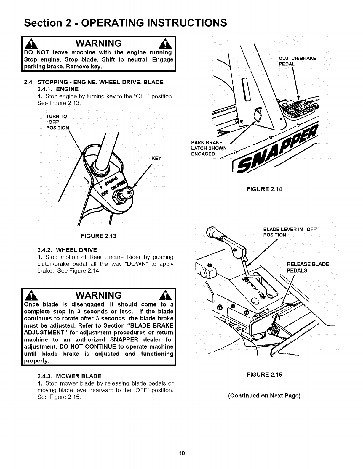
2.4.1. ENGINE
1. Stop engine by turning key to the "OFF" position.
See Figure 2.13.
PARK BRAKE
LATCH SHOWN
ENGAGED
CLUTCH/BRAKE
PEDAL
FIGURE 2.14
FIGURE 2.13
2.4.2. WHEEL DRIVE
1. Stop motion of Rear Engine Rider by pushing
clutch/brake pedal all the way "DOWN" to apply
brake. See Figure 2.14.
WARNING
Once blade is disengaged, it should come to a
complete stop in 3 seconds or less. If the blade
continues to rotate after 3 seconds, the blade brake
must be adjusted. Refer to Section "BLADE BRAKE
ADJUSTMENT" for adjustment procedures or return
machine to an authorized SNAPPER dealer for
adjustment. DO NOT CONTINUE to operate machine
until blade brake is adjusted and functioning
properly.
2.4.3. MOWER BLADE
1. Stop mower blade by releasing blade pedals or
moving blade lever rearward to the "OFF" position.
See Figure 2.15.
BLADE LEVER IN "OFF"
POSITION
RELEASE BLADE
PEDALS
FIGURE 2.15
(Continued on Next Page)
10
Page 4
Section 2 - OPERATING INSTRUCTIONS
2.4
STOPPING - ENGINE, WHEEL DRIVE, BLADE
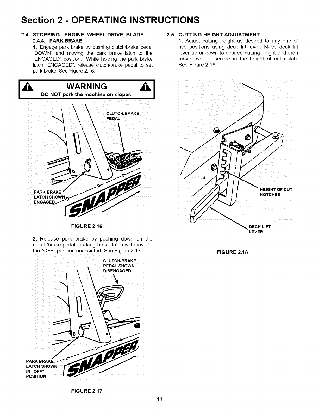
2.4.4. PARK BRAKE
1. Engage park brake by pushing clutch/brake pedal
"DOWN" and moving the park brake latch to the
"ENGAGED" position. While holding the park brake
latch "ENGAGED", release clutch/brake pedal to set
park brake. See Figure 2.16.
I,_ WARNING _I
DO NOT park the machine on slopes.
CLUTCH/BRAKE
PEDAL
2.5. CUTTING HEIGHT ADJUSTMENT
1. Adjust cutting height as desired to any one of
five positions using deck lift lever. Move deck lift
lever up or down to desired cutting height and then
move over to secure in the height of cut notch.
See Figure 2.18.
/
/
PARK BRAKE
LATCH SHOWN
FIGURE 2.16
2. Release park brake by pushing down on the
clutch/brake pedal, parking brake latch will move to
the "OFF" position unassisted. See Figure 2.17.
CLUTCH/BRAKE
PEDAL SHOWN
\ DISENGAGED
HEIGHT OF CUT
DECK LIFT
LEVER
FIGURE 2.18
PARK BRAKE
LATCH SHOWN
IN "OFF"
POSITION
FIGURE 2.17
11
Page 5

Section 2 - OPERATING INSTRUCTIONS
2.6 REVERSE LOCKOUT MECHANISM
Data indicates that tragic back-over accidents occur
each year. These accidents usually involve
unsupervised children. Many times these children have
been given rides on the machine and have been trained
to view this potentially dangerous piece of machinery as
fun rather than being taught how to avoid danger.
This riding mower has a Reverse Lockout Mechanism.
This mechanism prevents the mower from being shifted
into reverse with the blade running. To shift into reverse
you must first stop the blade by releasing the blade
pedals and then shift to reverse. It is our
recommendation that this mechanism remain functional
and the operator of this equipment develop the habit of
never backing up with the blade running. As the Safety
Instructions Indicate, DO NOT operate blades in
reverse. STOP BLADES, LOOK AND SEE BEHIND
AND DOWN for children, pets and hazards before
and while backing.
We realize that this could cause a change to your
previous mowing method but we encourage you to
adjust to this new system. Do not defeat the Reverse
Lockout Mechanism.
2.6.1. Reverse Lockout Mechanism Override
1. Stop machine. Stop blade.
2. Depress and hold Override Lever.
3. Depress and hold Blade Pedals. Release
Override Lever.
4. Move blade lever forward to "ON" position.
LOOK and SEE behind and down for children,
and hazards before and while backing.
IMPORTANT: DO NOT use the Reverse Lockout
Mechanism Override as the normal operating mode. To
return to the Reverse Lockout Mechanism mode,
release blade pedals to turn blade off. The Override will
reset to Reverse Lockout. Check the Reverse Lockout
Mechanism frequently for proper function. With the
blade pedals depressed, the shift lever must not go into
reverse. DO NOT operate machine if Reverse Lockout
Mechanism is not functioning properly. Contact your
local Snapper dealer for assistance.
If you operate your mower near roadways or use
attachments that require quicker shifting to reverse,
there is an override lever provided. This lever can be
pushed and held before starting the blade and wilt allow
reverse operation until the blade pedals are released, at
which time the system will return to its Reverse Lockout
mode. This feature should never be selected unless you
are absolutely sure that no children or others are
present in the mowing area and that all children are
away and supervised by a responsible adult.
DANGER
LOOK and SEE behind and down for children, pets
and hazards before and while backing.
BLADES must be turned off before backing
machine.
DO NOT allow children on machine (even with
blades off) or in yard when mowing.
12
Page 6

Section 3 - MAINTENANCE
WARNING
DO NOT attempt any adjustments, maintenance,
service or repairs with the engine running. STOP
engine. STOP blade. Engage parking brake. Remove
key. Remove spark plug wire from spark plug and
secure away from plug. Engine and components are
HOT. Avoid serious burns, allow all parts to cool
before working on machine. Fuel Filler Cap and vent
must be closed securely to prevent fuel spillage.
3.1
INTRODUCTION
To retain the quality of the Rear Engine Rider, use
genuine SNAPPER replacement parts only. Contact a
local SNAPPER dealer for parts and service
assistance. For the correct part or information for a
particular Rear Engine Riding Mower, always mention
the model and serial number. SNAPPER recommends
returning the Rear Engine Rider to an authorized
SNAPPER dealer annually for inspection and addition
of any new devices which might upgrade the safety of
the Rear Engine Rider. For the nearest SNAPPER
dealer in your area, check the yellow pages under the
heading LAWN MOWERS. For engine parts and
service, look for the engine manufacturer's dealers
under the heading, ENGINES - gasoline.
3.2
SERVICE - AFTER FIRST 5 HOURS
Routine maintenance is important to the performance
and life of your Rear Engine Rider. Service performed
properly and at the recommended interval is essential.
Refer to Section "MAINTENANCE SCHEDULE" in this
manual and in the Engine Owner's Manual. Carefully
complete all of the recommended service procedures.
3.2.1. CHANGE ENGINE OIL
1. Place bricks or wooden blocks under the front
wheels to lower rear of engine.
2. Loosen or remove oil fill cap on engine.
3. Loosen oil drain plug.
4. Place a 2 quart minimum capacity container
under the end of the oil drain. Open oi drain. See
Figure 3.1 for oil drains used on the Rear Engine
Riders.
5. After all the oil has drained, close the drain and
wipe up any oil that may have spilled. See Figure 3.1.
Dispose of used oil properly.
6. Fill engine crankcase with new oil. Refer to your
engine owner's manual for oil specifications.
3.2.2. SERVICE ENGINE AIR CLEANER
The engine is equipped with a dual element air
cleaner. Both the foam pre-cleaner and cartridge
require service. Refer to Engine Owner's Manual for
recommended service procedures.
3.2.3. CHECK MOWER BLADE
1. Follow WARNING statement found on this page.
2. Check fuel level in tank. If over 3/4 full, remove
tank. Refer to Section "REMOVING FUEL TANK". If
3/4 or less, proceed to next step.
3. Carefully stand Rear Engine Rider on rear bumper.
WARNING
Remove the battery if the Rear Engine Rider will be
left standing on the rear bumper for longer than 2
hours. See Section on BATTERY REMOVAL. DO
NOT use a cutting blade that shows signs of
excessive wear or damage on the Rear Engine Rider.
Refer to Section on MOWER BLADE REPLACEMENT
for proper blade inspection and service procedures.
4. Check torque of blade mounting bolts. As
necessary, torque to 30 to 40 ft. Ibs. See Figure 3.2.
5. Check blade for sharpness, wear and damage.
See Section on BLADE WEAR LIMITS.
REMOVE OIL
PLUG TO ALLOW
OIL TO DRAIN
BOLTS TO 30 TO
40 FT, LB8,
\
FIGURE 3.2
6. Check blade for straightness.
"ADJUSTING MOWER BLADE".
FIGURE 3.1
13
Refer to Section
Page 7

Section 3 - MAINTENANCE
WARNING
DO NOT attempt any adjust_nents,maintenance, service or
repairswith the engine running. STOP engine. STOP blade.
Engage parking brake. Remove key. Remove spark plug
wire from spark plug and secure away from plug. Engine
and components are HOT. Avoid serious bums, allow all
partsto cool beforeworking on machine. FuelFillerCap and
vent must be closedsecurelyto prevent fuel spillage.
3.2 SERVICE - AFTER FIRST 5 HOURS
3.2.4. CHECK BLADE DRIVE BELT
The blade drive consists of a single belt from the
engine to the deck. Inspect for signs of deterioration
and proper tension.
1. Lower deck to lowest setting.
2. Remove four self-tapping screws, two on each
side of mower drive belt cover. See Figure 3.3.
3. Slide cover back and rotate out.
REMOVE FOUR (4)
SELF-TAPPING ......
REMOVE
3.2.5. BLADE BRAKE
1. Check blade brake for proper function. Blade should
stop rotating in 3 seconds or less after moving the blade
control lever to the "OFF" position or after releasing the
blade pedals.
I Blades must stop rotating in 3 seconds or less after I
the blade has been turned off. DO NOT operate l
machine until blade brake has been adjusted and l
functioning properly. I
2. If the blade continues to rotate longer than 3
seconds do not operate machine. Refer to Section
"BLADE BRAKE ADJUSTMENT" or contact your
SNAPPER dealer for assistance.
3.2.6. SERVICE BRAKE / PARK BRAKE
1. Check machine brake for proper function. Engage
park brake. Push machine. Rear tires should skid. Drive
machine forward and apply brake. Machine should come
to a complete stop in less than 5 ft.
2. If brakes are not functioning properly brake
adjustment must be completed before operating
machine. Refer to Section "SERVICE BRAKE - PARK
BRAKE ADJUSTMENT".
FIGURE 3.3
4. With engine "OFF" and deck in 3rd height of cut
position, move blade lever back to the "ON" position
and depress blade pedals.
5. Measure the belt spacing at idler pulley. See
Figure 3.4. The belt spacing should be 1 1/4" but
no less 1". If the measurement is less than 1", the belt
tension should be adjusted. Refer to Section "MOWER
DRIVE BELT ADJUSTMENT".
ENGINE
._t PULLEY
BELT SPACING -_
SHOULD BE
1-1/4"
IDLER
PULLEY
3.2.7. INTERLOCK SYSTEM
Check interlock controls for proper function:
The engine MUST NOT start if:
1. Blade Control is "ON" and/or clutch/brake pedal is
released.
The engine and blades MUST STOP if:
2. The operator leaves the operator position with Blade
Control "ON" and/or clutch/brake pedal is released.
DO NOT operate machine if interlock system t
functioning properly. Contact your SNAPPER r
WARNING I
immediately for assistance,
3.2.8. REVERSE LOCKOUT MECHANISM
Check function of Reverse Lockout Mechanism with
engine off.
1. Depress and hold blade pedals.
2. Depress and hold clutch/brake pedal.
3. Shift lever must not go into reverse.
WARNING
DO NOT operate machine if Reverse LockoutI
Mechanism is not functioning properly. Contact your l
SNAPPER dealer immediately for assistance. I
FIGURE 3.4
MOWER
DECK
PULLEY
14
Page 8

Section 4 - ADJUSTMENTS & REPAIR
Once blade is disengaged it should come to a stop
in 3 seconds or less. If the blade continues to rotate
after 3 seconds the blade brake must be adjusted.
DO NOT continue to operate the machine if the blade
brake is not operating properly.
4.2.2. BLADE BRAKE ADJUSTMENT
The automatic Blade Brake should stop the blades
within seconds anytime the blades are
disengaged by moving blade lever to the "OFF"
position or by releasing the Blade Pedals. When
the Blade Brake is properly adjusted there should
be 1/16" to 1/8" clearance between the Blade
Engagement Lever and the back of the Latch
Plate. Check this by disengaging the Blade Lever
and depressing the Blade Pedals as shown in
Figure 4.2. If clearance is greater than 1/4"
perform the following adjustment.
1. Remove Belt Cover. Refer to Section "BLADE
BELT COVER REMOVAL".
2. With the blade engagement lever disengaged,
hold the blade pedals down and measure the
distance between the front of the blade lever and the
rear of the latch plate. The dimension should be 1/16"
to 1/8" clearance between lever and plate. See Figure
4.5. If the dimension is incorrect go to step 3.
3. If dimension is greater than 1/8", rotate nut
clockwise to increase brake tension. If dimension is
less than 1/16", rotate nut counter-clockwise to
decrease brake tension. See Figure 4.4.
4. Reinstall spindle cover.
engag_ it shoL
ss. lft :bladec
WARNING i
he blaq , blake
toope tethern
ting pr )erly.
E BRA "A)JU_
c Blad_ _rat:e sh, :te,_
3
WARNING
DO NOT operate machine until blade brake is
adjusted and functioning properly. If blade stop time
can not be achieved with the adjustment procedure
described above, take machine immediately to an
authorized Snapper dealer.
FIGURE 4.5
DO NOT attempt any adjustments, maintenance, service
or repairs with the engine running. Stop engine. Stop
blade. Engage parking brake. Remove key. Remove
spark plug wire from spark plug and secure away from
plug. Engine and components are HOT. Avoid serious
burns, allow all parts to cool before working on machine.
Fuel Filler Cap and Vent must be closed securely to
prevent fuel spillage.
4.2.3. MOWER DECK ADJUSTMENT
(Side-To-Side Levelness)
Before making deck leveling adjustments, check the tire
pressure. Front tires 12 psi, rear tires 12 psi. If tires are
properly inflated and mowing is still uneven, adjust side-
to-side deck levelness.
1. Place Rider on a smooth level surface.
2. Follow WARNING statement found on this page.
3. Place a piece of angle iron, pipe, or similar object
under center of deck at the rear.
4. Remove rear hanger chains and allow center, rear of
deck to rest on angle iron.
5. Measure the distance from blade tips to floor. If the
measurement is within 1/8" from side-to-side, the deck
attitude is satisfactory. If difference from side-to-side is
greater than 1/8",continue with adjustment.
6. Loosen the carriage bolt and nut retaining the left
side of the front lift arm and adjuster. Only loosen the
bolt and nut to the point where some tension remains
but liftarm can be moved.
ROTATE NUT CLOCKWISE TO
INCREASE BRAKE TENSION
ROTATE NUT COUNTER CLOCKWISE TO
DECREASE BRAKE TENSION
FIGURE 4.4
BLADE PEDAL
FRONT LIFT ARM
FIGURE 4.6
19
Page 9

Section 4 - ADJUSTMENTS & REPAIR
WARNING
DO NOT attempt any adjustments, maintenance,
service or repairs with the engine running. Stop
engine. Stop blade. Engage parking brake. Remove
key. Remove spark plug wire from spark plug and
secure away from plug. Engine and components are
HOT. Avoid serious burns, allow all parts to cool
before working on machine. Fuel Filler Cap and
Vent must be closed securely to prevent fuel
spillage.
4.3 REAR ENGINE RIDER DRIVE COMPONENTS
Your Snapper rider is equipped with a patented
smooth start clutch. The clutch should operate
smoothly and provide ample traction. If problems are
experienced, contact your Snapper dealer for repair.
4.3.1. SERVICE BRAKE/PARK BRAKE
ADJUSTMENT
Test the wheel brake on a dry concrete surface.
When properly adjusted, the Rear Engine Rider will
stop within 5 feet from fastest speed. If stopping
distance is more than 5 feet, the wheel brake should
be adjusted as follows:
1. Follow WARNING statement found on this page.
2. Check fuel level in tank. If over 3/4 full, remove
tank. Refer to Section "REMOVING FUEL TANK". If
3/4 or less, proceed to next step.
3. Carefully stand Rear Engine Rider on rear
bumper.
4. Depress clutch/brake pedal all the way down.
Move and hold the park brake latch in the
"ENGAGED" position and release the clutch/brake
pedal to set the park brake. See Figure 4.8.
CABLE
HOUSING
CABLE END
COTTER
PIN
7. Adjust cable up or down using the jam-nuts to
obtain a distance 3/4" between end of clutch/brake
cable (adjustment shown in inset of Figure 4.9) and
bottom of housing. See Figure 4.9.
8. After adjustment is complete, securely tighten
cable jam-nuts.
9. Retest wheel brake function.
CHAIN
CASE I t I
COTTER PIN
FIGURE 4.9
CLUTCH/BRAKE
FIGURE 4.8
5. Measure the distance between end of
clutch/brake cable and bottom of housing.
Measurement should be 3/4". See inset of Figure
4.9.
6. If measurement is less than 314", loosen the two
jam-nuts. See Figure 4.10. Hold the clutch/brake
cable to the chain case bracket.
\
BRAKE CABLE
CHAIN CASE
FIGURE 4.10
21
Page 10

Section 4 - ADJUSTMENTS & REPAIR
WARNING
DO NOT attempt any adjustments, maintenance,
service or repairs with the engine running. STOP
engine. STOP blade. Engage parking brake. Remove
key. Remove spark plug wire from spark plug and
secure away from plug. Engine and components are
HOT. Avoid serious burns, allow all parts to cool
before working on machine. Fuel Filler Cap and vent
must be closed securely to prevent fuel spillage.
DO NOT use a cutting blade that shows signs of
excessive wear or damage on the Rear Engine Rider.
On Rear Engine Riders equipped with a grass
catcher attachment, the air lifts should be replaced
when the blade is replaced.
MOWER BLADE REPLACEMENT '___' /
4.4
4.4.1. BLADE WEAR LIMITS
1. Inspect blade frequently for signs of excessive
wear or damage See Figure 4.11.
5. Inspect condition of blade. See Figure 4.11.
6. If blade is in good condition, sharpen at 22 to 28
degrees. DO NOT sharpen beyond existing cutting
edge. See Figure 4.13.
7. Check blade balance after sharpening. If
necessary, correct blade balance by grinding the
heavy end of blade.
8. Reinstall blade. See Figure 4.12. Torque blade
mounting bolts to recommended range of 30 to 40
ft. Ibs.
NUT LOCKWASHER
DANGEROUS CONDITION!
NOT USE ON MOWER! .....................................
REPLACE WITH NEW BLADE, DO NOT SHARPEN
Do
FIGURE 4.11
WARNING AI
Blades are extremely sharp and can cause severe I
injuries. Wear heavy leather gloves when working on or I
handling blades. DO NOT use blades that show signs I
of wear or damage. I
4.4.2. BLADE SHARPENING
1. Follow WARNING statement found on this page.
2. Check fuel level in tank. If over 3/4 full, remove
tank. Refer to Section "REMOVING FUEL TANK". If
3/4 or less, proceed to next step.
3. Carefully stand Rear Engine Rider on rear bumper.
4. Remove blade. See Figure 4.12.
FIGURE 4.12
ORIGINALBEYOND 028o__ "--" _. \
22 T --
.....................................
/
ORIGINAL CUTTING EDGE
FIGURE 4.13
22
Page 11

MAINTENANCE SCHEDULE
SUBJECT
Engine
Engine
Engine
AirPre-Cleaner
AirCleaner
SparkPlug
FuelFilter
EngineCooling
System
Battery
Battery
Tires
DriveBelts
MowerBlades
MowerDeck
LubricationPoints
SERVICE
TO BE PERFORMED
Check Oil Level
Initial Oil Change
Periodic Oil Change
Service Sponge Pre-
Cleaner Element
Replace Element
Replace Plugs
Replace Filter
Clean Shrouds & Fins
Check Electrolyte
Charge Battery
Check Pressures
Check For Wear And
Tension
Check For Wear And
Damage
Clean Debris
Accumulation
Grease or Oil
REFERENCE
PAGES
Page 6
Page 13
Page 13
Engine Manual
Engine Manual
Engine Manual
Page 17
Engine Manual
Page 25
Page 24 & 25
Page 6
Pages 14,18,23
Pages 22
Page 15 X
Pages 15 & 16
EACH
USE
6
HOURS
X
X
X
26
HOURS
X
X
X
X
X
60
HOURS
X*
100
HOURS
X
X
X**
EACH
SEASON
X
X
X
X
X
LubricateChainCase
Check Grease Level
Pages 16
&Transmission
BladeBrake
StoppingTime
Clutch/BrakeSystem
ReverseLockout
Check blade stopping
for proper operation
Check Clutch/Brake for
proper operation
Check function
Pages 14 & 19 X
Page 14 & 21 X
Page 6 & 14 X X
Mechanism
InterlockSystem
*Change oil every 25 hours when operating under heavy load or high temperatures.
**Clean more often under dusty conditions or when air debris is present
Check function
Page 14 X
X
X
X
X
29
Page 12

Generally, wash foam-type filters
In a dlshwashlng detergent and
water solution. Rinse and wring
dry, then saturate with oil and
squeeze out excess. Failure to
re-oil this type filter will ruin the
engine.
Clean paper elements by tapping
lightly. Blowing with air will
rupture paper elements.
Use a flashlight to detect clogged
or torn paper elements - replace If
damaged in any way.
PRIMARY MAINTENANCE
Air Is also needed to keep
your engine cool. Dirt, dust
& debris build up to restrict
and clog cooling air Intake
screens and fins. Clean
screens and fins at frequent
Intervals. The engine blower
housing and shrouds should
be removed at least once
each season or more often
under dry, dusty conditions
for a thorough cleaning of
fins.
Failure to keep external
surfaces clean not only
presents fire hazards, but
"causes overheating and
resulting engine damages
such as:
1. distorted valve guides
2. sticking valves
t_°o. 3. scuffed, scored
.,,_. walls
4. overspeedlng
5. loss of power
6. complete failure of
engine.
Dirt can also be introduced
Into an engine In dirty fuel
from a contaminated
container. Always use clean
fresh fuel from a clean
container to guard against
dirt, sludge and water
contamination.
Be aware that fuel breaks
down in storage and forms
gummy compounds which
will block carburetor pass-
ages. Never use fuel more
than 3 months old. Drain
tank then run the engine out
of fuel before storing during
the off-season.
An engine must also have proper lubrication.
All engines use some oil. On 4-cycle engines,
CHECK OIL LEVEL BEFORE EACH START-UP.
Wipe area clean around the oll check plug or
dipstick opening to keep dirt from falling Into
the engine when checking the oil Always
check with the machine on a level surface.
On engines with dipstick, keep the level up to,
but not over, the FULL mark. When adding o11,
allow time for all of the oll to flow down the fill
tube to prevent a false full reading when the
level could actually be low and result In engine
damage.
34
Page 13

PRIMARY MAINTENANCE
On 4-cyle engines with an oil level plug,
don't be fooled into thinking the engine has
sufficient lubricating oii if you can see "some"
oil in the opening - the level should always be
brought up to the point of lg at the
top of the fill hole,
I
Change oil at regular Intervals using a a high
quality oil such as Snapper's small engine
formulated 4-cycle engine oil Refer to the
engine owner's manual for oil details.
On 2-cycle engines, lubrication must be
provided by an exact mixture of gasoline
and 2-cycle air-cooled engine oil A 2-cycle
engine that Is mistakenly run on straight
gasoline will be ruined in less than 5
minutesl If you keep straight gasoline In
addition to pre-mixed 2-cycle engine fuel,
be sure the containers are clearly marked
to avoid mix-up.
Snapper 2-cycle engines require a 32 to 1
mixture of gasoline and BIA certified TC-W
oil such as Snapper's 2-cycle engine oil
Many of the 2-cycle engine oils on the
market today make fantastic claims, but for
the best performance and long engine life,
always use Snapper 2-cycle oil Pre-mix
the fuel and always shake the container
before filling the tank.
STARTING CHECK LIST
1. Engine 011
2. Air Cleaner
3. Fuel Tank
4. Choke
5. Primer (on
some engines)
6, Safety Inter-
lock Switches
7. Switch &
Blade Control
8. Spark plug
g. Throttle
control
10. Blade
11. Muffler
• To full level (4-cycle)
• Properly mixed with gas
• Clean and properly serviced
• Full fresh clean gasoline
• Fuel valve open
• Cap vent open
• Inline filter clean
• Operating properly
• Used properly
• In proper position
• All wires properly connected
• Switch On
• Blade control properly
• Wire connected
• Good connecUon
• Start position
• Sharpened
• Good condition
• Not clogged
• Grass & leaves cleaned away
(2 cycle)
positioned on walk mower
ProperlyInstalled and
torqued
Read and follow all safety "_
Instructions in safety book-
lets and manuals.
Keep in mind that dirt Is your engine's enemy
#1 both Internally and externallyl Internally,
dirt will quickly ruin an engine and externally
It will cause overheating and resulting Internal
Damage caused by Improper lubri-
poor air cleaner service or overheating
due to dirt cannot be covered under warranty.
It only takes a few moments to service the
engine (and equipment) on a routine baals
but the rewards will be a quick starUng, re-
sponsive engine that will provide long
astisfactory service with minimum maintananca
cost. The prestart checklist In the next column
and Instructions In your Snapper Operator's
Manual are designated to help you keep your
Snapper In top operating condition with
minimum effortl
J
35
 Loading...