

Page 1
Parts
p
Manual
SW20 Series
Walk-Behind Mower
Models:
5900702 SW20KAV1336, 36" 13HP Kawasaki Walk Behind Mower
5900700 SW20KAV1748, 48" 17HP Kawasaki Walk Behind Mower
Briggs and Stratton Yard Power Products Group
5375 North Main Street
Munnsville, NY 13409 USA
800-933-6175
Descri
tion:
5101265
Rev. Date:
TP 400-7338-IR-WD-SP
1/2008
IRRevision
Page 2

Page 3

Table Of Content
s
.
.
g
g
.
.
y
.
.
.
y
.
g
.
MODEL COMPONENTS PAGE
Front Frame Group ............................................................................................................................................................
Handle Bar & Instrument Control Group ............................................................................................................................
Fuel Tank & Mount Group ..................................................................................................................................................
En
ine Deck Group ............................................................................................................................................................
En
ine & PTO Group - 13 HP & 17 HP Kawasaki .............................................................................................................
Pump Drive Group .......................... ...................................................................................................................................
Motion Control Group - Upper ............................................................................................................................................
Motion Control Group - Lower ............................................................................................................................................
H
draulic Group .................................................................................................................................................................
Parking Brake Group .........................................................................................................................................................
Deck Lift Group ..................................................................................................................................................................
Transmission SERVICE PARTS ........................................................................................................................................
Tire & Wheel Group ..................... ......................................................................................................................................
Decal Group - Safety & Operation .....................................................................................................................................
Decal Group - Brand & Model ............................................................................................................................................
36" & 48" Mower Deck - Spindle Service Parts ..................................................................................................................
48" Mower Deck - Rollers Group ........................................................................................................................................
36" Mower Deck - Housing, Covers, Spindles & Blades ....................................................................................................
36" Mower Deck - Pulle
48" Mower Deck - Housin
48" Mower Deck - Belts, Pulleys & Idler Arm .....................................................................................................................
Electrical Schematic - 13 HP & 17 HP Kawasaki Models ...................................................................................................
s, Belts & Idler Arm .....................................................................................................................
, Covers, Spindles & Blades ....................................................................................................
Torque Specification Chart ............................................................................................. Inside Back Cover
10
12
14
16
18
20
22
24
26
28
30
32
34
36
38
40
42
44
46
4
6
8
Page 4
Front Frame Group
NOTE: Unless noted otherwise, use
the standard hardware torque
specification chart.
The above parts group applies to the following Mfg. Nos.:
5900702
5900700
© Copyright Briggs and Stratton. All Rights Reserved.
2008
4
TP 400-7338-IR-WD-SP
Page 5

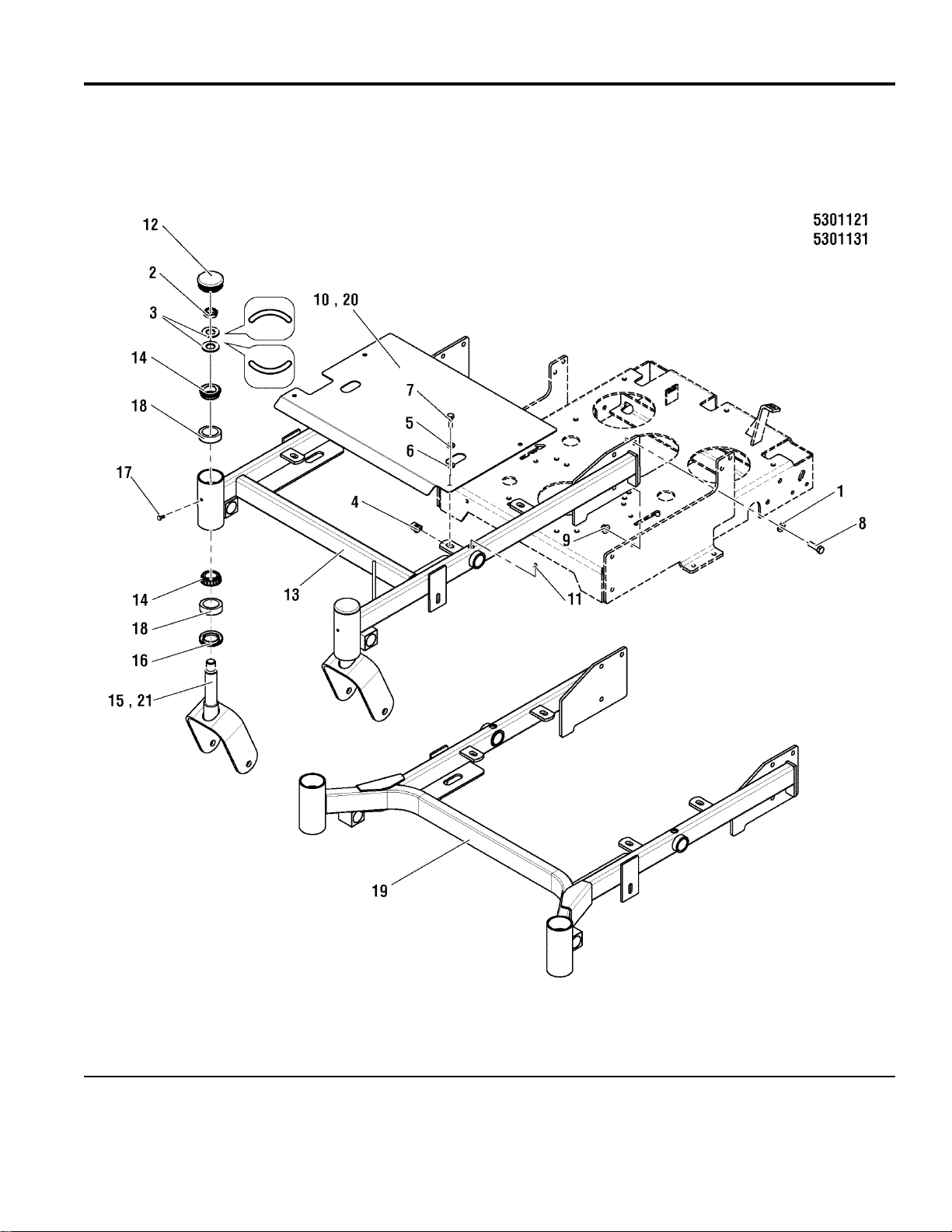
Front Frame Group
PART NO. DESCRIPTIONREF NO. QTY.
1 5025158 6 WASHER, 1/2 SAE
2 5025448 2 NUT, 3/4-16, HEX JAM NYLON LOCK
3 5025449 4 WASHER, BELLEVILLE - 1.500 X .755
4 5025452 4 BODY CLIP, 5/16-18 -1/4 MATERIAL
5 5025170 4 WASHER, 5/16 LOCK YZ
6 5025155 4 WASHER, 5/16 SAE
7 5025011X8 4 BOLT, 5/16-18 X 1 GD5 YZ
8 5025017X10 6 BOLT, 1/2-13 X 1-1/4 GD5
9 5025396 6 NUT, 1/2-13 HEX NYLOCK FLANGE
10 5403338D 1 PLATE, DECK GUARD - SNP PRO WB 36 (13 HP MODELS ONLY)
11 5021637 2 GREASE FITTING, PRESS, SHORT
12 5100882 2 CAP, CASTER SPINDLE, LOW PROFILE
13 5403289D 1 WELD,FRONT FRAME, 36 SNP PRO WB - RED (13 HP MODELS ONLY)
14 5020884 4 BEARING, TAPERED ROLLER, 1"
15 5402240D 2 WELD, CASTER YOKE, SW20 - 36" RED (13 HP MODELS ONLY)
16 5021072 2 SEAL GREASE
17 5025457 2 BOLT, 1/4-28 X 1/2, GD5 YZ
18 5020883 4 CUP, BEARING (SV)
19 5403626D 1 WELD, FRONT FRAME, 48 WB - RED (17 HP MODELS ONLY)
20 5403429D 1 GUARD, DECK LIFT (17 HP MODELS ONLY)
21 5403627D 2 WELD, CASTER YOKE, SW20 - 48" RED (17 HP MODELS ONLY)
Footnotes
The above parts group applies to the following Mfg. Nos.:
5900702
5900700
© Copyright Briggs and Stratton. All Rights Reserved.
2008
5
TP 400-7338-IR-WD-SP
Page 6
Handle Bar & Instrument Control Group
NOTE: Unless noted otherwise, use
the standard hardware torque
specification chart.
The above parts group applies to the following Mfg. Nos.:
5900702
5900700
© Copyright Briggs and Stratton. All Rights Reserved.
2008
6
TP 400-7338-IR-WD-SP
Page 7

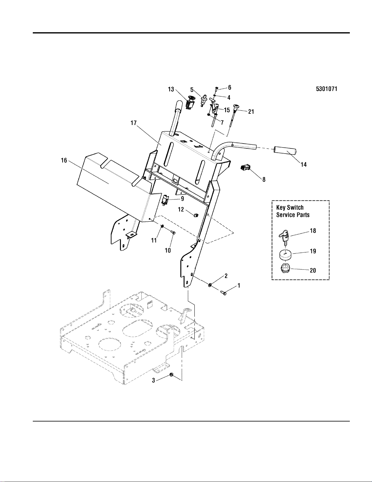
Handle Bar & Instrument Control Group
PART NO. DESCRIPTIONREF NO. QTY.
1 5025013X8 6 BOLT, 3/8-16 X 1 GD5 YZ
2 5025293 6 WASHER, 3/8 GD.9 FLAT
3 5025394 6 NUT, 3/8-16 HEX NYLOCK FLANGE
4 5025154 2 WASHER, 1/4 SAE
5 5021842 1 SWITCH, IGNITION, 2 POST (Includes Ref Nos 18 - 20)
6 5025010X6 2 BOLT, 1/4-20 X 3/4 GD5 YZ
7 5025391 2 NUT, 1/4-20 HEX NYLOCK FLANGE
8 5101280 1 SWITCH, PLUNGER, NO/NC SNAP-IN, LOW PROFILE
9 5101216 1 SWITCH, PLUNGER, NC, SINGLE POLE SNAP-IN
10 5025011X6 4 BOLT, 5/16-18 X 3/4 GD5
11 5025155 4 WASHER, 5/16 SAE
12 5022308 4 BODY CLIP, 5/16-18 X 1/2 DEEP
13 5022180 1 SWITCH, BLADE ENGAGEMENT
14 5021841 2 GRIP, FOAM, .940" X 5" X .187"
15 5101213 1 CABLE, THROTTLE, 54"
16 5403605D 1 COVER, FRONT HANDLEBAR - RED
17 5403094D 1 WELD, HANDLE BAR - RED
18 5022789 1 KEY, IGNITION, MOLDED SET (SV)
19 5022790 1 COVER (SV)
20 5022791 1 PLASTIC NUT (SV)
21 5047912 1 CABLE, CHOKE CONTROL, 56"
Footnotes
The above parts group applies to the following Mfg. Nos.:
5900702
5900700
© Copyright Briggs and Stratton. All Rights Reserved.
2008
7
TP 400-7338-IR-WD-SP
Page 8
Fuel Tank & Mount Group
NOTE: Unless noted otherwise, use
the standard hardware torque
specification chart.
The above parts group applies to the following Mfg. Nos.:
5900702
5900700
© Copyright Briggs and Stratton. All Rights Reserved.
2008
8
TP 400-7338-IR-WD-SP
Page 9

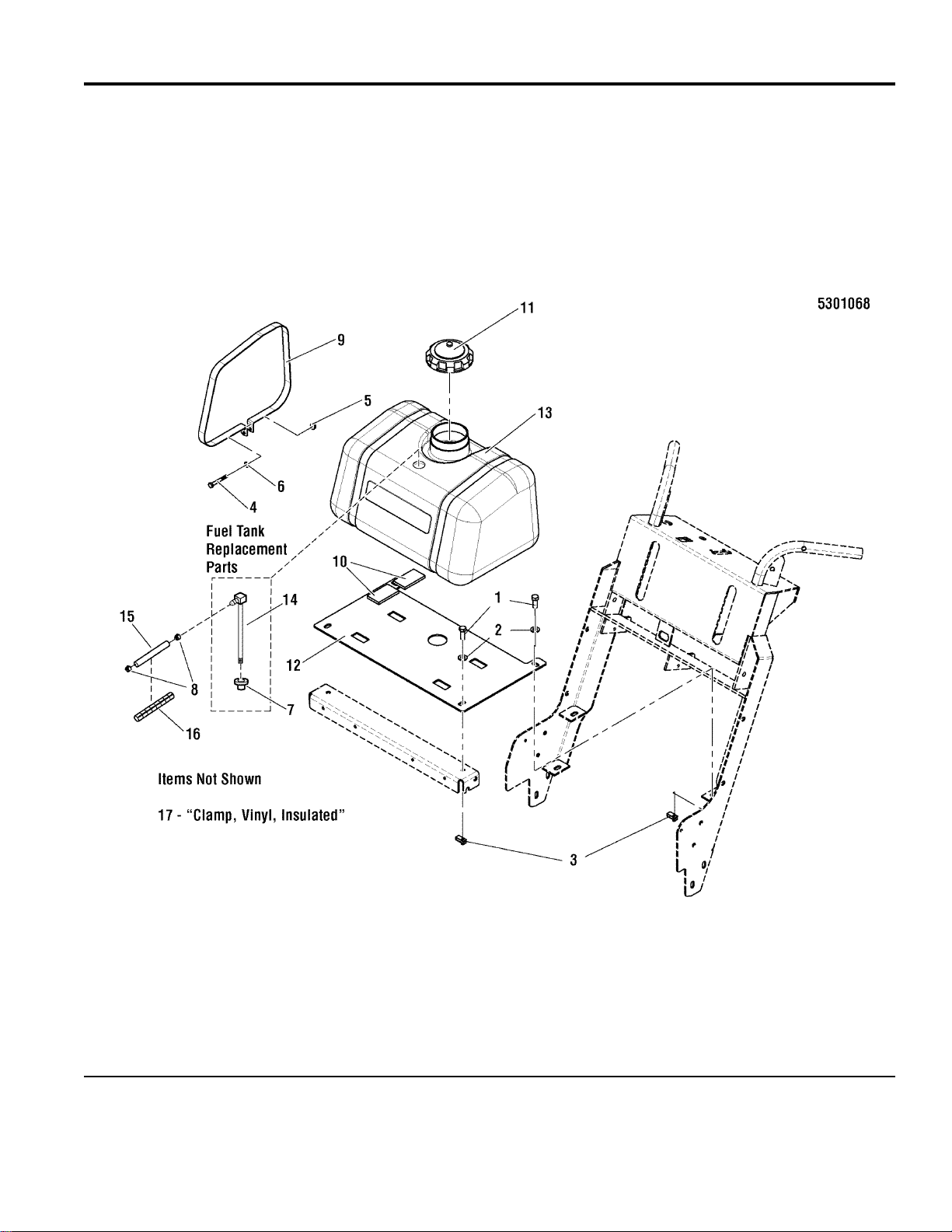
Fuel Tank & Mount Group
PART NO. DESCRIPTIONREF NO. QTY.
1 5025013X8 4 BOLT, 3/8-16 X 1 GD5 YZ
2 5025156 4 WASHER, 3/8 SAE
3 5022649 4 BODY CLIP, 3/8-16 X .688" DEEP
4 5025010X16 2 BOLT, 1/4-20 X 2", GD5
5 5025391 2 NUT, 1/4-20 HEX NYLOCK FLANGE
6 5025154 2 WASHER, 1/4 SAE
7 5600050 1 KIT, BUSHING (SV)
8 5020835 2 CLAMP, HOSE, EXTERNAL, 1/2 - RED
9 5403445A 2 STRAP, FUEL TANK - SNP PRO DDS - BLK
10 5101270 4 PAD, RUBBER MOUNT, 1/4 MAT
11 5101272 1 FUEL CAP, 3.5", VENTED
12 5403229D 1 PLATE, FUEL TANK MOUNT - RED
13 5101231 1 TANK, FUEL, SNAPPER PRO WALK BEHIND (Includes Ref Nos 7 & 14)
14 5101261 1 PICKUP TUBE ASM, FUEL TANK, 8.0" (SV)
15 5050831X19 1 HOSE, 1/4" FUEL, 19.00"
16 5050833X18 1 WIRE LOOM, 1/2" ID, 18" LONG
17 5021500 1 CLAMP, VINYL INSULATED (NOT SHOWN - ATTACHES TO ENGINE)
Footnotes
The above parts group applies to the following Mfg. Nos.:
5900702
5900700
© Copyright Briggs and Stratton. All Rights Reserved.
2008
9
TP 400-7338-IR-WD-SP
Page 10
Engine Deck Group
NOTE: Unless noted otherwise, use
the standard hardware torque
specification chart.
The above parts group applies to the following Mfg. Nos.:
5900702
5900700
© Copyright Briggs and Stratton. All Rights Reserved.
2008
10
TP 400-7338-IR-WD-SP
Page 11

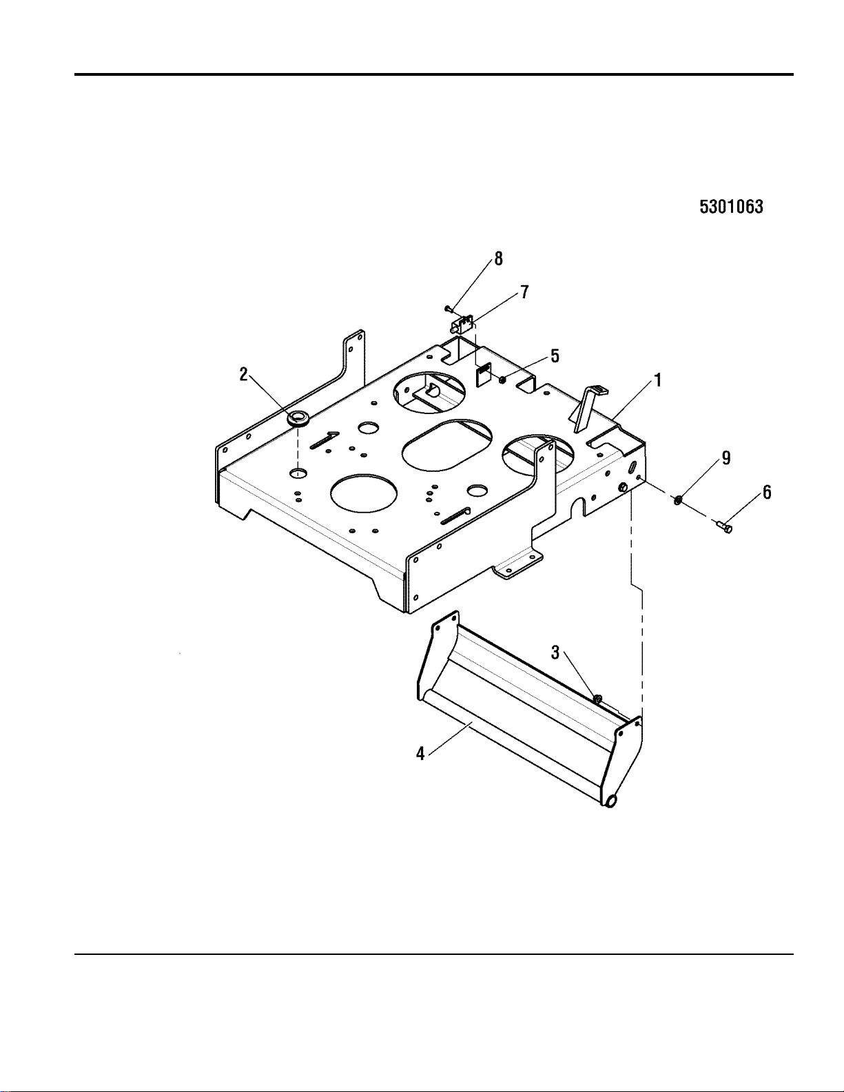
Engine Deck Group
PART NO. DESCRIPTIONREF NO. QTY.
1 5403082D 1 WELD, ENGINE DECK, SNP PRO WB - RED
2 5021379 1 GROMMET, 7/8
3 5025392 4 NUT, 5/16-18 HEX NYLOCK FLANGE
4 5403441D 1 WELD, BUMPER - SNP PRO DDS - RED
5 5025029 2 NUT, #10-24 HEX
6 5025011X8 4 BOLT, 5/16-18 X 1 GD5 YZ
7 5021769 1 SWITCH, PLUNGER, N.C.
8 5025179X4 2 SCREW, #10-24 X 1/2 ROUND PHILLIPS
9 5025155 4 WASHER, 5/16 SAE
Footnotes
The above parts group applies to the following Mfg. Nos.:
5900702
5900700
© Copyright Briggs and Stratton. All Rights Reserved.
2008
11
TP 400-7338-IR-WD-SP
Page 12
Engine & PTO Group - 13 HP & 17 HP Kawasaki
NOTE: Unless noted otherwise, use
the standard hardware torque
specification chart.
The above parts group applies to the following Mfg. Nos.:
5900702
5900700
© Copyright Briggs and Stratton. All Rights Reserved.
2008
12
TP 400-7338-IR-WD-SP
Page 13

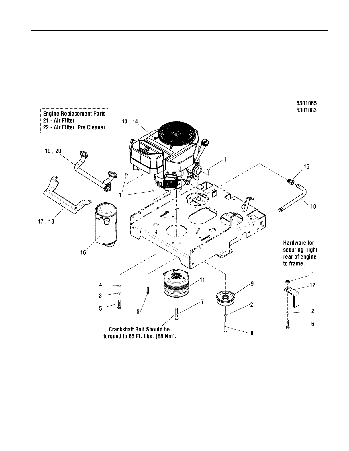
Engine & PTO Group - 13 HP & 17 HP Kawasaki
PART NO. DESCRIPTIONREF NO. QTY.
1 5025057 4 NUT, 5/16-18 HEX NYLON LOCK
2 5025292 1 WASHER, 5/16 GD.9 FLAT
3 5025155 1 WASHER, 5/16 SAE
4 5025188 1 WASHER, 5/16" INT. TOOTH LOCK
5 5025011X12 2 BOLT, 5/16-18 X 1-1/2" GD5 YZ
6 5025011X14 1 BOLT, 5/16-18 X 1-3/4 GD5 YZ
7 5047632 1 BOLT, CRANKSHAFT, 7/16X2-3/4, PATCH YZ
8 5025011X20 1 BOLT, 5/16-18 X 2-1/2" GD5 YZ
9 5022621 1 PULLEY, IDLER, SINGLE FLANGE
10 5048681 1 HOSE, OIL DRAIN
11 5101175 1 CLUTCH, WARNER, SNAPPER PRO WALK
12 5403009D 1 ANCHOR, CLUTCH - RED
13 - 1 ENGINE, 13HP KAW, FH381V-AS21 (13 HP MODELS ONLY)
14 - 1 ENGINE, 17HP KAW, FH541V-AS21 (17 HP MODELS ONLY)
15 5022234 1 ADAPTER, OIL DRAIN
16 7075551X3 1 MUFFLER (SV)
17 7075434X2 1 HEAT SHIELD, EXHAUST MANIFOLD (SV) (13 HP MODELS ONLY)
18 7075551X5 1 HEAT SHIELD, EXHAUST MANIFOLD (SV) (17 HP MODELS ONLY)
19 7075434X1 1 MANIFOLD. EXHAUST (SV) (13 HP MODELS ONLY)
20 7075551X4 1 MANIFOLD. EXHAUST (SV) (17 HP MODELS ONLY)
21 7075551X1 1 AIR FILTER (SV)
22 7075551X2 1 PRE AIR FILTER (SV)
Footnotes
The above parts group applies to the following Mfg. Nos.:
5900702
5900700
© Copyright Briggs and Stratton. All Rights Reserved.
2008
13
TP 400-7338-IR-WD-SP
Page 14
Pump Drive Group
NOTE: Unless noted otherwise, use
the standard hardware torque
specification chart.
The above parts group applies to the following Mfg. Nos.:
5900702
5900700
© Copyright Briggs and Stratton. All Rights Reserved.
2008
14
TP 400-7338-IR-WD-SP
Page 15

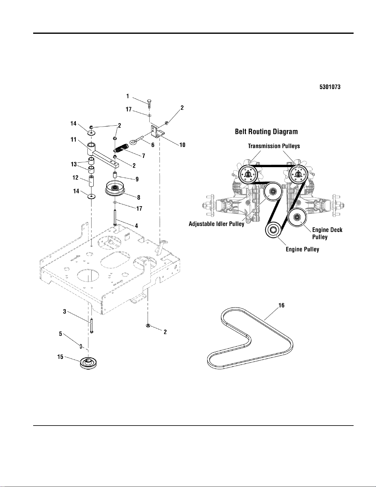
Pump Drive Group
PART NO. DESCRIPTIONREF NO. QTY.
1 5025013X8 1 BOLT, 3/8-16 X 1 GD5 YZ
2 5025394 5 NUT, 3/8-16 HEX NYLOCK FLANGE
3 5025013X28 1 BOLT, 3/8-16 X 3-1/2 GD5 YZ
4 5025013X32 1 BOLT, 3/8-16 X 4 GD5 YZ
5 5050407X8 1 KEY, 1/4 SQ. X 1.00
6 5025429 1 EYE BOLT, 3/8-16 X 4", 3/4" EYE
7 1608395 1 SPRING-EXTN 1.040ODX 04.000LG .105WIRE D
8 5022621 1 PULLEY, IDLER, SINGLE FLANGE
9 5101245 1 SPACER, .38 X .75 X 1.25, YZ
10 5045200D 1 WELD, ANCHOR EYEBOLT
11 5046430D 1 WELD, ARM, PUMP DRIVE IDLER - RED
12 5045135 1 SPACER, .39 X 1.00 X 2.55
13 5022157 2 BUSHING, BRASS, 1.25X1X1.25
14 5025305 2 WASHER, .41 X 1.75 X .14
15 5101311 1 PULLEY, CRANKSHAFT
16 5021770 1 BELT, #7-5331
17 5025156 2 WASHER, 3/8 SAE
Footnotes
The above parts group applies to the following Mfg. Nos.:
5900702
5900700
© Copyright Briggs and Stratton. All Rights Reserved.
2008
15
TP 400-7338-IR-WD-SP
Page 16

Motion Control Group - Upper
NOTE: Unless noted otherwise, use
the standard hardware torque
specification chart.
The above parts group applies to the following Mfg. Nos.:
5900702
5900700
© Copyright Briggs and Stratton. All Rights Reserved.
2008
16
TP 400-7338-IR-WD-SP
Page 17

Motion Control Group - Upper
PART NO. DESCRIPTIONREF NO. QTY.
1 7090095 2 NUT, HEX 1/4F GR5 YZ
2 5025154 10 WASHER, 1/4 SAE
3 5025010X6 5 BOLT, 1/4-20 X 3/4 GD5 YZ
4 5025391 9 NUT, 1/4-20 HEX NYLOCK FLANGE
5 5101287A 2 LEVER, REVERSE HANDLE
6 5025211 5 PIN, HAIR, .0585 X 1-1/8, 1/4 EYE, YZ
7 5025213X8 2 PIN, CLEVIS, 5/16 X 1 YZ
8 5025392 1 NUT, 5/16-18 HEX NYLOCK FLANGE
9 5025010X14 3 BOLT, 1/4-20 X 1-3/4" GD5 YZ
10 5025288 1 WASHER, 1/4" FENDER
11 5021773 1 SPRING, BRAKE
12 5025164 1 WASHER, 5/16" FENDER
13 5025013X20 1 BOLT, 3/8-16 X 2-1/2"
14 5010546 3 COLLAR, 3/8" SET
15 5025033 2 NUT, 5/16-24 HEX
16 5020979 2 CLEVIS, 5/16-24, PLASTIC
17 5101244 2 ROD, REVERSING, SNP PRO WB
18 5020047 2 COLLAR, 5/16" SET
19 5025212X7 2 PIN, CLEVIS, 1/4 X 7/8
20 5021104 2 CLEVIS, 1/4-28, PLASTIC
21 5101242 2 ROD, OPC LINK, SNP PRO WB
22 5025394 2 NUT, 3/8-16 HEX NYLOCK FLANGE
23 5403307D 2 WELD, REVERSE HANDLE - RED
24 5101215 2 SPACER, .26 X .38 X 1.250, YZ
25 5025220 2 BOLT, 3/8-16 x 1-1/2", 1/2" SHOULDER
26 5025156 2 WASHER, 3/8 SAE
27 5025097 1 NUT, 3/8-24 HEX NYLON LOCK
28 5101236 1 ROD, CRUISE CONTROL, SNP PRO WB
29 5403239D 1 WELD, OPC SHAFT- RED
30 5403282A 1 FLAP, OPC - LH - SNP WB
31 5403283A 1 FLAP, OPC - RH - SNP WB
32 5101274 1 SPACER, .26 X .50 X 1.00 YZ
33 5044726 2 DDS BRAKE PUCK
34 5403778 1 PLATE, FRICTION CONTROL
35 5403776D 1 WELD, SPEED CONTROL,DDS - RED
36 5100744 1 BAR, SPEED CONTROL, DIPPED
37 5101245 1 SPACER, .38 X .75 X 1.25, YZ
38 5022392 1 ROD END, 3/8-24 LH FEMALE
39 5020805 1 SPACER, .38 X .75 1.25 YZ
Footnotes
The above parts group applies to the following Mfg. Nos.:
5900702
5900700
© Copyright Briggs and Stratton. All Rights Reserved.
2008
17
TP 400-7338-IR-WD-SP
Page 18

Motion Control Group - Lower
NOTE: Unless noted otherwise, use
the standard hardware torque
specification chart.
The above parts group applies to the following Mfg. Nos.:
5900702
5900700
© Copyright Briggs and Stratton. All Rights Reserved.
2008
18
TP 400-7338-IR-WD-SP
Page 19

Motion Control Group - Lower
PART NO. DESCRIPTIONREF NO. QTY.
1 5025125 2 NUT, 7/16-14 HEX NYLON LOCK
2 5025139 2 NUT, 5/16-18 HEX SERRATED FLANGE (LARGE)
3 5025055X14 1 BOLT, 5/16-18 X 1-3/4 GD5 TFL
4 5101281 1 SPACER, .26 X .50 X .50 YZ
5 5101339 2 SPRING, EXTENSION, 3.281 X .751 X .075 WIRE
6 5010580 2 COLLAR, 1/2" SET
7 5101352 2 SPACER, .33 X .50 X .75, YZ
8 5403330D 1 WELD, PEDAL, NEUTRAL RETURN - RED
9 5025015X6 2 BOLT, 7/16-14 X 3/4, GD 5 YZ
10 5025391 4 NUT, 1/4-20 HEX NYLOCK FLANGE
11 5025189X24 2 EYE BOLT, 1/4-20 X 3, ZC
12 5101414 1 WASHER, .390 X 1.25 X 1.00, YZ
13 5025013X16 1 BOLT, 3/8-16 X 2 GD5 YZ
14 5025394 5 NUT, 3/8-16 HEX NYLOCK FLANGE
15 5023212 2 NUT, 5/16-24 HEX, LH
16 5025011X16 2 BOLT, 5/16-18 X 2", GD5
17 5025288 2 WASHER, 1/4" FENDER
18 5025010X18 1 BOLT, 1/4-20 X 2-1/4", GD5
19 5025010X14 1 BOLT, 1/4-20 X 1-3/4" GD5 YZ
20 5100832 2 SLEEVE, CRUISE CONTROL ROLLER
21 5021098 2 BEARING, BRONZE FLANGE, 3/4
22 5101243 2 ADJUSTER, ROD LINKAGE 5/16-24
23 5100766 2 ROLLER, SPEED CONTROL
24 5101240 2 ROD, CONTROL RAMP
25 5021146 2 BALL JOINT, 5/16-24, FEMALE
26 5025013X8 4 BOLT, 3/8-16 X 1 GD5 YZ
27 5025156 4 WASHER, 3/8 SAE
28 5101262 1 SPACER, .38 X 1.13 X 1.00 STEP, YZ
29 5403406D 1 WELD, CONTROL ARM - RH - RED
30 5403405D 1 WELD, CONTROL ARM - LH - RED
31 5403353D 1 WELD, CONTROL SHAFT - RED
32 5025392 2 NUT, 5/16-18 HEX NYLOCK FLANGE
Footnotes
The above parts group applies to the following Mfg. Nos.:
5900702
5900700
© Copyright Briggs and Stratton. All Rights Reserved.
2008
19
TP 400-7338-IR-WD-SP
Page 20

Hydraulic Group
NOTE: Unless noted otherwise, use
the standard hardware torque
specification chart.
The above parts group applies to the following Mfg. Nos.:
5900702
5900700
© Copyright Briggs and Stratton. All Rights Reserved.
2008
20
TP 400-7338-IR-WD-SP
Page 21

Hydraulic Group
PART NO. DESCRIPTIONREF NO. QTY.
1 5025292 8 WASHER, 5/16 GD.9 FLAT
2 5020047 4 COLLAR, 5/16 SET
3 5025156 3 WASHER, 3/8 SAE
4 5025013X8 3 BOLT, 3/8-16 X 1 GD5 YZ
5 5025394 3 NUT, 3/8-16 HEX NYLOCK FLANGE
6 5025010X8 4 BOLT, 1/4-20 X 1", GD5
7 5025391 4 NUT, 1/4-20 HEX NYLOCK FLANGE
8 5025154 4 WASHER, 1/4 SAE
9 5025011X14 2 BOLT, 5/16-18 X 1-3/4 GD5 YZ
10 5025011X44 2 BOLT, 5/16-18 X 5-1/2, GD 5, YZ
11 5025392 6 NUT, 5/16-18 HEX NYLOCK FLANGE
12 5025011X22 4 BOLT, 5/16-18 X 2-3/4, GD 5, YZ
13 5403335D 2 PLATE, WHEEL SPACER - 1/4" - RED (13 HP MODELS ONLY)
14 5101276 2 ROD, HYDRO RELEASE, SNP PRO WB
15 5101189 1 TRANSMISSION, LH, HG ZH-KMBB-3A5A-1LLX
16 5101188 1 TRANSMISSION, RH, HG ZH-GMBB-3A5A-1LLX
17 5403228D 1 PLATE, HYD TANK MOUNT - RED
18 5100473 2 RESERVOIR, HYDRO OIL, 350 ML
19 5101176 1 SPACER, HYDRO LINK, SNP PRO WB
20 5101177 2 SPACER, .34 X .75 X 3.27, YZ
21 5050857X4P25 2 HOSE, 1/2" X 4.25 PUSH-ON
22 5025474 4 CLAMP, HOSE, .75 FREE DIA.
Footnotes
The above parts group applies to the following Mfg. Nos.:
5900702
5900700
© Copyright Briggs and Stratton. All Rights Reserved.
2008
21
TP 400-7338-IR-WD-SP
Page 22

Parking Brake Group
NOTE: Unless noted otherwise, use
the standard hardware torque
specification chart.
The above parts group applies to the following Mfg. Nos.:
5900702
5900700
© Copyright Briggs and Stratton. All Rights Reserved.
2008
22
TP 400-7338-IR-WD-SP
Page 23

Parking Brake Group
PART NO. DESCRIPTIONREF NO. QTY.
1 5020979 1 CLEVIS, 5/16-24, PLASTIC
2 5020047 2 COLLAR, 5/16" SET
3 5025211 4 PIN, HAIR, .0585 X 1-1/8, 1/4 EYE, YZ
4 5025017X12 1 BOLT, 1/2-13 X 1-1/2 GD5 YZ
5 5025396 1 NUT, 1/2-13 HEX NYLOCK FLANGE
6 5025158 1 WASHER, 1/2 SAE
7 5025045 1 NUT, 5/16-24 HEX NYLOCK
8 5021880 1 GRIP, FOAM
9 5023216 1 NUT, 5/16-24 JAM
10 5025213X8 1 PIN, CLEVIS, 5/16 X 1 YZ
11 5025010X6 4 BOLT, 1/4-20 X 3/4 GD5 YZ
12 5025391 4 NUT, 1/4-20 HEX NYLOCK FLANGE
13 5101116 1 ROD, PULLER ROD
14 5101123 2 BEARING, 1/2" FLANGED
15 5403361D 1 WELD BRAKE SHAFT - RED
16 5101253 1 SPRING-EXT, .75 OD X 3.40 LG, X .115 WR
17 5101246 1 ROD, LOWER BRAKE CONTROL
18 5023242 1 SPRING, CONTROL ROD
19 5403395D 1 WELD, BRAKE LINK CONNECTOR - RED
20 5403373D 1 PLATE, SPRING CONNECTOR - RED
21 5403312D 1 LINK, BRAKE PIVOT
22 5025155 1 WASHER, 5/16 SAE
23 5025154 1 WASHER, 1/4 SAE
Footnotes
The above parts group applies to the following Mfg. Nos.:
5900702
5900700
© Copyright Briggs and Stratton. All Rights Reserved.
2008
23
TP 400-7338-IR-WD-SP
Page 24

Deck Lift Group
NOTE: Unless noted otherwise, use
the standard hardware torque
specification chart.
The above parts group applies to the following Mfg. Nos.:
5900702
5900700
© Copyright Briggs and Stratton. All Rights Reserved.
2008
24
TP 400-7338-IR-WD-SP
Page 25

Deck Lift Group
PART NO. DESCRIPTIONREF NO. QTY.
1 5025401 2 WASHER, 3/8" USS
2 5025394 6 NUT, 3/8-16 HEX NYLOCK FLANGE
3 5025013X16 2 BOLT, 3/8-16 X 2 GD5 YZ
4 5042658 2 SPACER, .39 X .75 X 1.06
5 5025293 4 WASHER, 3/8 GD.9 FLAT
6 5025013X10 4 BOLT, 3/8-16 X 1-1/4 GD5
7 5025396 10 NUT, 1/2-13 HEX NYLOCK FLANGE
8 5403332D 2 WELD, CRANK, DECK LIFT - RED
9 5021733 2 KNOB, PLASTIC, 1/2-13
10 5025017X40 2 BOLT, 1/2-13 X 5 GD5 YZ
11 5025150 16 WASHER, 1/2 USS
12 5101413 6 SPACER, .52 X 1.00 X 1.825
13 5403224D 4 BAR, DECK LIFT - ADJ - RED
14 5023356 16 BUSHING, 1.00X1.13X.75, PLA
15 5025017X22 6 BOLT, 1/2-13 X 2-3/4 GD5
16 5403477D 2 PLATE, DECK HEIGHT INDICATOR - SNP RED
17 7029259 2 STUD, LIFT
18 7046214 2 WELD, LIFT WASHER, YELLOW
19 5101310 2 POINTER, DECK HEIGHT
20 5025017X26 2 BOLT, 1/2-13 X 3-1/4 GD5
21 5043366 2 SPACER, .50 X 1.00 X 2.25
22 5100500 2 CAP, VINYL, .937 ID X 1.00
Footnotes
The above parts group applies to the following Mfg. Nos.:
5900702
5900700
© Copyright Briggs and Stratton. All Rights Reserved.
2008
25
TP 400-7338-IR-WD-SP
Page 26

Transmission SERVICE PARTS
NOTE: Unless noted otherwise, use
the standard hardware torque
specification chart.
The above parts group applies to the following Mfg. Nos.:
5900702
5900700
© Copyright Briggs and Stratton. All Rights Reserved.
2008
26
TP 400-7338-IR-WD-SP
Page 27

Transmission SERVICE PARTS
PART NO. DESCRIPTIONREF NO. QTY.
23 5101026X1 1 OIL FILTER1
41 5101026X2 1 SEAL, LIP, 18 X 32 X 7
56 5101026X3 1 SEAL, LIP, 17 X 40 X 7
57 5101026X4 1 RING, RET 2.06 INT
95 5101026X5 1 BEARING BALL, 1.0 X 52 X 15 OPEN 6205M
120 5101026X6 1 FAN, 7", 10 BLADE
121 5101026X7 1 PULLEY, 4.5 INCH
200 5101026X8 1 KIT SEAL
210 5101026X9 1 KIT, INPUT SHAFT
Footnotes
The above parts group applies to the following Mfg. Nos.:
5900702
5900700
© Copyright Briggs and Stratton. All Rights Reserved.
2008
27
TP 400-7338-IR-WD-SP
Page 28

Tire & Wheel Group
NOTE: Unless noted otherwise, use
the standard hardware torque
specification chart.
The above parts group applies to the following Mfg. Nos.:
5900702
5900700
© Copyright Briggs and Stratton. All Rights Reserved.
2008
28
TP 400-7338-IR-WD-SP
Page 29

Tire & Wheel Group
PART NO. DESCRIPTIONREF NO. QTY.
1 5021181S 2 TIRE ASSM, 9 X 3.5 X 4, SILVER
2 5025396 2 NUT, 1/2-13 HEX NYLOCK FLANGE
3 5021181X1 2 TIRE, FRONT 9 X 3.5 X 4 (SV)
4 5021181X2 2 TUBE (SV)
5 5021181X3 2 HUB & BEARING ASSEMBLY (SV)
6 5021182 2 BEARING, ROLLER (ONE PER TIRE)(SV)
7 5021043 2 RETAINER, BEARING (TWO PER TIRE)(SV)
8 5041657 2 AXLE, CASTER WHEEL
9 5025017X44 2 BOLT, 1/2-13 X 5-1/2" GD5 YZ
10 7050539 2 WHEEL ASSY, 18 X 6.50-8, TURF MASTER (13HP MODELS ONLY)
11 7078119 2 TIRE, 18 X 6.5 - 8, TURF MASTER (SV) (13HP MODELS ONLY)
12 7078114 2 RIM, 18 X 6.50, 4 BOLT (SV) (13HP MODELS ONLY)
13 5020601 8 NUT, 1/2-20, FOR WHEEL BOLT SILVER
14 7012234 2 VALVE STEM, SNAP IN (SV) (13HP MODELS ONLY)
15 5025158 2 WASHER, 1/2 SAE
16 5021045S 2 TIRE, 18 X 8.5 X 8, 4 PLY (17 HP MODELS ONLY)
17 5021074 2 TIRE ONLY (SV) (17 HP MODELS ONLY)
18 5021205S 2 WHEEL ONLY (SV) (17 HP MODELS ONLY)
Footnotes
The above parts group applies to the following Mfg. Nos.:
5900702
5900700
© Copyright Briggs and Stratton. All Rights Reserved.
2008
29
TP 400-7338-IR-WD-SP
Page 30

Decal Group - Safety & Operation
NOTE: Unless noted otherwise, use
the standard hardware torque
specification chart.
The above parts group applies to the following Mfg. Nos.:
5900702
5900700
© Copyright Briggs and Stratton. All Rights Reserved.
2008
30
TP 400-7338-IR-WD-SP
Page 31

Decal Group - Safety & Operation
PART NO. DESCRIPTIONREF NO. QTY.
1 5100812 1 DECAL, WARNING
2 5100711 1 DECAL, DANGER
3 5100712 1 DECAL, DANGER, FIRE (SP)
4 5100088 1 DECAL, DANGER, MOWER
5 5101292 1 DECAL, DANGER, MOWER DISCHARGE, SPDD
6 5101290 1 DECAL, CONTROL PANEL, SPDD
7 5100093 1 DECAL, WARNING, HAND IN PULLEY
8 5101291 2 DECAL, CUT HEIGHT, SPDD
9 5100490 1 DECAL, PEDAL
10 5101062 2 DECAL, TRANSAXLE RELEASE
11 5101294 1 DECAL, CUT HEIGHT,LH, SPDD
12 5101295 1 DECAL, CUT HEIGHT, RH, SPDD
Footnotes
The above parts group applies to the following Mfg. Nos.:
5900702
5900700
© Copyright Briggs and Stratton. All Rights Reserved.
2008
31
TP 400-7338-IR-WD-SP
Page 32

Decal Group - Brand & Model
NOTE: Unless noted otherwise, use
the standard hardware torque
specification chart.
The above parts group applies to the following Mfg. Nos.:
5900702
5900700
© Copyright Briggs and Stratton. All Rights Reserved.
2008
32
TP 400-7338-IR-WD-SP
Page 33

Decal Group - Brand & Model
PART NO. DESCRIPTIONREF NO. QTY.
1 5101322 1 DECAL, 36" (36" Models Only)
2 5022811 1 DECAL, 48" (48" Models Only)
3 5101320 1 DECAL, SW20
4 5101200 1 DECAL, SNAPPER PRO
Footnotes
The above parts group applies to the following Mfg. Nos.:
5900702
5900700
© Copyright Briggs and Stratton. All Rights Reserved.
2008
33
TP 400-7338-IR-WD-SP
Page 34

36" & 48" Mower Deck - Spindle Service Parts
NOTE: Unless noted otherwise, use
the standard hardware torque
specification chart.
The above parts group applies to the following Mfg. Nos.:
5900702
5900700
© Copyright Briggs and Stratton. All Rights Reserved.
2008
34
TP 400-7338-IR-WD-SP
Page 35

36" & 48" Mower Deck - Spindle Service Parts
PART NO. DESCRIPTIONREF NO. QTY.
1 5061095 1 ASSM, SPINDLE, LOW PROFILE (Includes Ref Nos. 2 - 10)
2 5023329 1 GREASE FITTING (SV)
3 5025405 1 NUT, 3/4-16 HEX (SV)
4 5025406 1 WASHER, 3/4 BELLEVILLE (SV)
5 5049793 2 TRASH SHIELD (SV)
6 5023330 2 BEARING (SV)
7 5023296 1 RELIEF VALVE (SV)
8 5061097 1 SPINDLE HOUSING (SV)
9 5061099 1 SPACER, 1.00 X 1.25 X 1.75 (SV)
10 5061098 1 SPINDLE SHAFT (SV)
Footnotes
The above parts group applies to the following Mfg. Nos.:
5900702
5900700
© Copyright Briggs and Stratton. All Rights Reserved.
2008
35
TP 400-7338-IR-WD-SP
Page 36

48" Mower Deck - Rollers Group
NOTE: Unless noted otherwise, use
the standard hardware torque
specification chart.
The above parts group applies to the following Mfg. Nos.:
5900700
© Copyright Briggs and Stratton. All Rights Reserved.
2008
36
TP 400-7338-IR-WD-SP
Page 37

48" Mower Deck - Rollers Group
PART NO. DESCRIPTIONREF NO. QTY.
1 5025013X28 2 BOLT, 3/8-16 X 3-1/2 GD5 YZ
2 5025156 2 WASHER, 3/8 SAE
3 5047027 2 SPACER, .51 X .75 X .56
4 5041931 4 SPACER, .38 X .50 X 1.25
5 1714760 2 WHEEL- 2.00 WIDE 3.92 DIA 0.531ID POLY
6 5025394 2 NUT, 3/8-16 HEX NYLOCK FLANGE
Footnotes
The above parts group applies to the following Mfg. Nos.:
5900700
© Copyright Briggs and Stratton. All Rights Reserved.
2008
37
TP 400-7338-IR-WD-SP
Page 38

36" Mower Deck - Housing, Covers, Spindles & Blades
NOTE: Unless noted otherwise, use
the standard hardware torque
specification chart.
The above parts group applies to the following Mfg. Nos.:
5900702
© Copyright Briggs and Stratton. All Rights Reserved.
2008
38
TP 400-7338-IR-WD-SP
Page 39

36" Mower Deck - Housing, Covers, Spindles & Blades
PART NO. DESCRIPTIONREF NO. QTY.
1 5600171 1 DECK SHELL W/ DECAL, 36" - SW20 (Includes Safety Decals)
2 5061095 2 ASSM, SPINDLE, LOW PROFILE
3 5023156 8 BOLT, 5/16-18 X 1 1/4 FLANGE
4 5025392 8 NUT, 5/16-18 HEX NYLOCK FLANGE
5 5021227S 1 BLADE, 18 (SET OF THREE) (Blades are sold in sets of three.)
6 5025320X14 2 BOLT, 5/8-11 X 1-3/4" GD8
7 5025477 2 WASHER, 5/8" GRADE 8, YZ
8 5402404 1 CHUTE, DISCHARGE, RUBBER, BENT (SV)
9 5402361D 1 WELD, FRAME CHUTE, 44/48/52 -SNP RED
10 5402362D 1 SUPPORT, DISCHARGE CHUTE, 44/48/52-SNP RED
11 5025013X12 2 BOLT, 3/8-16 X 1-1/2 GD5 YZ
12 5025394 2 NUT, 3/8-16 HEX NYLOCK FLANGE
13 5042555 1 ROD, BRAKE LINKAGE
14 5025045 2 NUT, 5/16-24 HEX NYLON LOCK
15 5600132 1 KIT, DISCHARGE CHUTE, SNAPPER PRO (SV) (Includes Ref. Nos 8 - 10)
Footnotes
The above parts group applies to the following Mfg. Nos.:
5900702
© Copyright Briggs and Stratton. All Rights Reserved.
2008
39
TP 400-7338-IR-WD-SP
Page 40

36" Mower Deck - Pulleys, Belts & Idler Arm
NOTE: Unless noted otherwise, use
the standard hardware torque
specification chart.
The above parts group applies to the following Mfg. Nos.:
5900702
© Copyright Briggs and Stratton. All Rights Reserved.
2008
40
TP 400-7338-IR-WD-SP
Page 41

36" Mower Deck - Pulleys, Belts & Idler Arm
PART NO. DESCRIPTIONREF NO. QTY.
1 5101312 2 PULLEY, IDLER, 5.00 WIDE W/ .51 BORE
2 5101313 1 BELT, 83.0 - 83.5 EL, B-SECTION
3 5045178 2 SPACER, .52 X 1.00 X .75
4 5100632 1 SPRING, EXTENSION, SWIVEL. LONG HOOK
5 5020095 1 GREASE FITTING, 1/4-28 STRAIGHT
6 5025406 2 WASHER, 3/4 BELLEVILLE
7 5050407X5 2 KEY, 1/4 SQ. X 1-1/4
8 5025405 2 NUT, 3/4-16 HEX
9 5025429 1 EYEBOLT, 3/8-16 X 4", 2-1/8" OF THREAD
10 5025394 4 NUT, 3/8-16 HEX NYLOCK FLANGE
11 5403902D 1 WELD, ANCHOR EYEBOLT - RED
12 5025017X36 1 BOLT, 1/2-13 X 4-1/2 GD5 YZ
13 5025158 1 WASHER, 1/2 SAE
14 5044960 1 SPACER, .39 X 1.00 X .25
15 5025150 1 WASHER, 1/2 USS
16 5025013X8 2 BOLT, 3/8-16 X 1 GD5 YZ
17 5025396 2 NUT, 1/2-13 HEX NYLOCK FLANGE
18 5025017X22 1 BOLT, 1/2-13 X 2-3/4 GD5
19 5045022 1 SPACER, .52 X 1.00 X 3.50
20 5021541 2 BUSHING, FLANGE
21 5025056 1 NUT, 1/2-13 HEX NYLON LOCK
22 5023178 2 PULLEY, 6.122 OD., 52" DECK
23 5403424D 1 WELD, IDLER ARM SHORT - RED
24 5025084 1 NUT, 3/8-16 HEX JAM
25 5100548 1 WASHER, .390 X 1.50 X .109 YZ
26 5101103 2 SHIELD, PULLEY BEARING
27 5025013X10 1 BOLT, 3/8-16 X 1-1/4 GD5
Footnotes
The above parts group applies to the following Mfg. Nos.:
5900702
© Copyright Briggs and Stratton. All Rights Reserved.
2008
41
TP 400-7338-IR-WD-SP
Page 42

48" Mower Deck - Housing, Covers, Spindles & Blades
NOTE: Unless noted otherwise, use
the standard hardware torque
specification chart.
The above parts group applies to the following Mfg. Nos.:
5900700
© Copyright Briggs and Stratton. All Rights Reserved.
2008
42
TP 400-7338-IR-WD-SP
Page 43

48" Mower Deck - Housing, Covers, Spindles & Blades
PART NO. DESCRIPTIONREF NO. QTY.
1 5600172 1 DECK SHELL W/ DECALS, 48" - SW20 (Includes Safety Decals)
2 5061095 3 ASSM, SPINDLE, LOW PROFILE
3 5023156 12 BOLT, 5/16-18 X 1 1/4 FLANGE
4 5025392 13 NUT, 5/16-18 HEX NYLOCK FLANGE
5 5025320X14 3 BOLT, 5/8-11 X 1-3/4" GD8
6 5025159 3 WASHER, 5/8 USS
7 5020843S 1 BLADE, 16.25 (SET OF THREE)
8 5401271D 1 WELD, DISCHARGE BAFFLE, 48 - SNP RED
9 5025145X6 3 BOLT, 5/16-18 X 3/4", CARRIAGE
10 5025392 3 NUT, 5/16-18 HEX NYLOCK FLANGE
11 5402361D 1 WELD, FRAME CHUTE, 44/48/52 -SNP RED
12 5402404 1 CHUTE, DISCHARGE, RUBBER, BENT, 44/48/52 (SV)
13 5402362D 1 SUPPORT,DISCHARGE CHUTE,44/48/52-SNP RED
14 5025013X12 2 BOLT, 3/8-16 X 1-1/2 GD5 YZ
15 5025394 2 NUT, 3/8-16 HEX NYLOCK FLANGE
16 5042555 1 ROD, BRAKE LINKAGE
17 5025155 9 WASHER, 5/16 SAE
18 5025045 2 NUT, 5/16-24 HEX NYLON LOCK
19 5025011X6 1 BOLT, 5/16-18 X 3/4 GD5
20 5022308 6 BODY CLIP, 5/16-18 X 1/2 DEEP
21 5025011X8 6 BOLT, 5/16-18 X 1 GD5 YZ
22 5403661D 1 GUARD, DECK, 48, DDS, LH - RED
23 5403660D 1 GUARD, DECK, 48, DDS, RH - RED
24 5600132 1 KIT, DISCHARGE CHUTE, 48/52 (SV) (INCLUDES REF NOS 11 - 15)
Footnotes
The above parts group applies to the following Mfg. Nos.:
5900700
© Copyright Briggs and Stratton. All Rights Reserved.
2008
43
TP 400-7338-IR-WD-SP
Page 44

48" Mower Deck - Belts, Pulleys & Idler Arm
NOTE: Unless noted otherwise, use
the standard hardware torque
specification chart.
The above parts group applies to the following Mfg. Nos.:
5900700
© Copyright Briggs and Stratton. All Rights Reserved.
2008
44
TP 400-7338-IR-WD-SP
Page 45

48" Mower Deck - Belts, Pulleys & Idler Arm
PART NO. DESCRIPTIONREF NO. QTY.
1 5021650 1 BELT,# 7-5335
2 5021976 1 PULLEY, IDLER 6-3/4
3 5061305D 1 WELD, IDLER ARM - RED
4 5020095 1 GREASE FITTING, 1/4-28 STRAIGHT
5 5021541 2 BUSHING, FLANGE
6 5061339 1 SPACER, .52 X 1.00 X 3.42
7 5050407X5 3 KEY, 1/4 SQ. X 1-1/4
8 5025150 1 WASHER, 1/2 USS
9 5025017X36 1 BOLT, 1/2-13 X 4-1/2 GD5
10 5025396 4 NUT, 1/2-13 HEX NYLOCK FLANGE
11 5025405 3 NUT, 3/4-16 HEX
12 5100632 1 SPRING, EXTENSION, SWIVEL
13 5025158 1 WASHER, 1/2 SAE
14 5025017X22 3 BOLT, 1/2-13 X 2-3/4 GD5
15 5023264 1 PULLEY, FLAT IDLER, 5.0 X .75
16 5023175 3 PULLEY, 5.72., 48 DECK
17 5025332 1 NUT, 1/2-13 HEX SIDE LOCK
18 5025017X32 1 BOLT, 1/2-13 X 4 GD5
19 5050857X2P5 1 HOSE, 1/2" PUSH-ON 2.50"
20 5025406 3 WASHER, 3/4 BELLEVILLE
21 5101103 3 SHIELD, PULLEY BEARING
22 5047142 1 SPACER, .52 X 1.25 X .70
23 5025056 1 NUT, 1/2-13 HEX NYLON LOCK
24 5025440 2 WASHER, 1/2 GD9 YZ
25 5100548 1 WASHER, .390 X 1.50 X .109 YZ
26 5044960 1 SPACER, .39 X 1.00 X .25
27 5045178 1 SPACER, .52 X 1.00 X .75
28 5044609 1 SPACER, .52 X 1.00 X .38
29 5025013X10 1 BOLT, 3/8-16 X 1-1/4 GD5
30 5025394 1 NUT, 3/8-16 HEX NYLOCK FLANGE
31 5101312 1 PULLEY, IDLER, 5.00 WIDE W/ .51 BC
Footnotes
The above parts group applies to the following Mfg. Nos.:
5900700
© Copyright Briggs and Stratton. All Rights Reserved.
2008
45
TP 400-7338-IR-WD-SP
Page 46

Electrical Schematic - 13 HP & 17 HP Kawasaki Models
5403383
The above parts group applies to the following Mfg. Nos.:
5900702
5900700
© Copyright Briggs and Stratton. All Rights Reserved.
#Name
46
TP 400-7338-IR-WD-SP
Page 47

Hardware Identification & Torque Specifications
Common Hardware Types
Hex Head Capscrew
Carriage Bolt
Standard Hardware Sizing
When a washer or nut is identified as 1/2”, this is the
Nominal size
second number is present it represent the
When bolt or capscrew is identified as 1/2 - 16 x 2”, this
means the
second number represents the
example, and the final number is the
bolt or screw (in this example 2 inches long).
, meaning the
Nominal size
inside diameter
, or
body diameter
threads per inch
body length
Washer
Lockwasher
Hex Nut
is 1/2 inch; if a
threads per inch
is 1/2 inch; the
(16 in this
of the
The guides and ruler furnished below are designed to
help you select the appropriate hardware and tools.
0
1/4 3/4
1/2
Nut, 1/2”
Inside
Diameter
1
1/4 3/4
1/2
Screw, 1/2 x 2
2
1/4 3/4
1/2
3
1/4 3/4
1/2
4
Body
Diameter
Body
Length
Torque Specification Chart
FOR STANDARD MACHINE HARDWARE (Tolerance ± 20%)
Hardware
Grade
Size Of
Hardware ft/lbs Nm. ft/lbs Nm. ft/lbs Nm.
8-32
8-36
10-24
10-32
1/4-20
1/4-28
5/16-18 11 15.0 17 23.1 25 34.0
5/16-24 12 16.3 19 25.8 27 34.0
3/8-16 20 27.2 30 40.8 45 61.2
3/8-24 23 31.3 35 47.6 50 68.0
7/16-14 30 40.8 50 68.0 70 95.2
7/16-20 35 47.6 55 74.8 80 108.8
1/2-13 50 68.0 75 102.0 110 149.6
1/2-20 55 74.8 90 122.4 120 163.2
9/16-12 65 88.4 110 149.6 150 204.0
9/16-18 75 102.0 120 163.2 170 231.2
5/8-11 90 122.4 150 204.0 220 299.2
5/8-18 100 136 180 244.8 240 326.4
3/4-10 160 217.6 260 353.6 386 525.0
3/4-16 180 244.8 300 408.0
7/8-9 140 190.4 400 544.0 600 816.0
7/8-14 155 210.8 440 598.4 660 897.6
1-8 220 299.2 580 788.8 900 1,244.0
1-12 240 326.4 640 870.4 1,000 1,360.0
1. These torque values are to be used for all hardware
excluding: locknuts, self-tapping screws, thread forming
screws, sheet metal screws and socket head setscrews.
2. Recommended seating torque values for locknuts:
a. for prevailing torque locknuts - use 65% of grade 5
torques.
b. for flange whizlock nuts and screws - use 135% of
grade 5 torques.
3. Unless otherwise noted on assembly drawings, all torque
values must meet this specification.
No
Marks
SAE Grade 2 SAE Grade 5 SAE Grade 8
in/lbs in/lbs
19
20
27
31
66
76
2.1
2.3
3.1
3.5
7.6 8 10.9 12 16.3
8.6 10 13.6 14 19.0
30
31
43
49
NOTES
3.4
3.5
4.9
5.5
in/lbs
41
43
60
68
420 571.2
4.6
4.9
6.8
7.7
Wrench & Fastener Size Guide
1/4
1/4” Bolt or Nut
Wrench—7/16”
5/16
5/16” Bolt or Nut
Wrench—1/2”
3/8
3/8” Bolt or Nut
Wrench—9/16”
7/16
DIA.
7/16” Bolt or Nut
Wrench (Bolt)—5/8”
Wrench (Nut)—11/16”
1/2
DIA.
1/2” Bolt or Nut
Wrench—3/4”
Page 48

Parts
Manual
SW20 Series
Walk-Behind Mower
IT IS THE POLICY OF FERRIS INDUSTRIES TO IMPROVE ITS PRODUCTS WHENEVER IT
IS POSSIBLE AND PRACTICAL TO DO SO. WE RESERVE THE RIGHT TO MAKE
CHANGES OR ADD IMPROVEMENTS AT ANY TIME WITHOUT INCURRING ANY
OBLIGATION TO MAKE SUCH CHANGES ON PRODUCTS MANUFACTURED
Briggs and Stratton Yard Power Products Group
5375 North Main Street
Munnsville, NY 13409 USA
800-933-6175
www.ferrisindustries.com
© Copyright Briggs and Stratton Corporation
All Rights Reserved. Printed In USA.
2008
 Loading...