

Page 1
DEALER SET-UP INSTRUCTIONS and PRE-SALE CHECKLIST for SNAPPER
EUROPEAN LARGE FRAME SNOW THROWERS
INTRODUCTION: The Snapper Large Frame Snow Throwers are shipped almost fully assembled and require
minimal set-up. Setting up the machine will require the handles to be unfolded and secured, and the attachment
of the chute crank rod. Some models may also require the installation of the electric start kit to the engine.
Complete each of the following steps carefully.
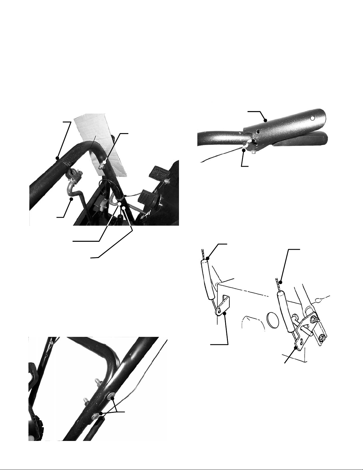
STEP 1: HANDLES: Cut both wire ties that secure the
control cables to the handles. Be very careful and DO
NOT cut the control cables. Cut the wire tie that secures
the chute crank to the handle. See Figure 1.
CUT CABLE TIE
THAT SECURES
CHUTE CRANK
LOOSEN NUT
REMOVE
CARDBOARD
CHUTE
CRANK
CUT CABLE TIES
ON BOTH
HANDLES
DO NOT CUT
CONTROL CABLE
FIGURE 1
STEP 2: HANDLES: Loosen handle nuts and speed
control rod nut. Rotate handles up to the operating
position. Remove shipping cardboard from in between
handles. See Figure 1. Insert bolts through both upper
& lower handles and secure with nuts. Make sure the
square necks of the bolts are recessed into the square
holes of upper handles. Tighten nuts securely. See
Figure 2.
SECURE UPPER
HANDLES WITH
BOLTS AND NUTS
TIGHTEN SECURELY
FIGURE 2
STEP 3: HANDLES: Cut both wire ties that secure the
control levers to the handles. See Figure 3.
CONTROL
LEVER
CHECK “Z” BEND END OF CABLE
IS SECURELY INSE RTED INTO
HOLE ON CONTROL LEVER
FIGURE 3
STEP 4: CABLES: Make sure that the cables are
connected to the traction clutch rod and blower clutch
bracket. IMPORTANT : Cables should have some slack
and should not be under tension. Both controls must
pivot freely. See Figure 4.
TRACTION
CLUTCH
CABLE
(LEFT SIDE)
BLOWER
CLUTCH
CABLE
(RIGHT SIDE)
TRACTION
CLUTCH
ROD
BLOWER
CLUTCH
BRACKET
FIGURE 4
INSTRUCTION No. 7-4367 (I.R. 05/9/01)
Page 2
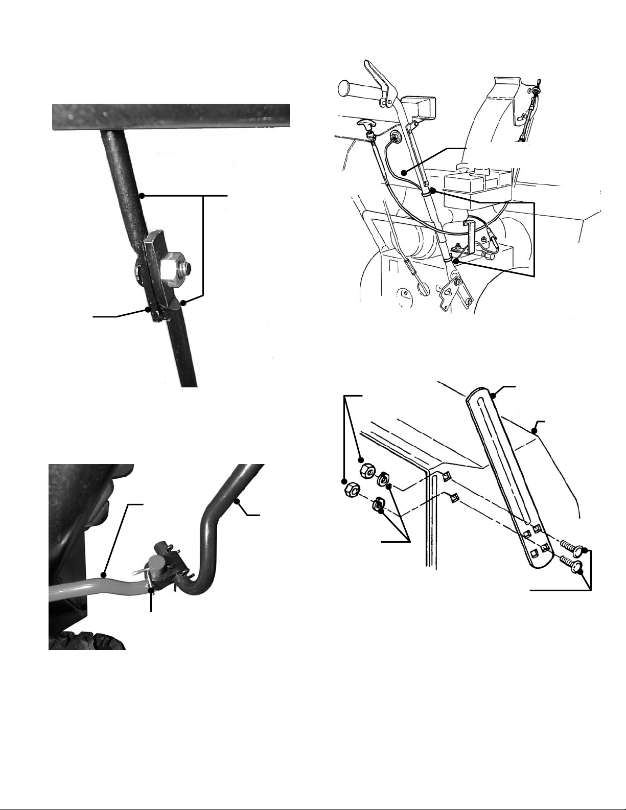
STEP 5: CONTROL ROD: : Cut wire ties that secure the
BOLT
ground speed control handle and control rods. Secure both
halves of the ground speed control rod together.
IMPORTANT: Make sure alignment tab and slot on the
two rod halves are engaged together. Tighten nut securely.
See Figure 5.
GROUND SPEED
CONTROL ROD
MAKE SURE TAB
AND SLOT ARE
ENGAGED
FIGURE 5
STEP 6: CHUTE CRANK: Connect chute crank to worm
gear shaft and secure with cotter pin. See Figure 6.
WORM
GEAR
SHAFT
CHUTE
CRANK
SECURE WITH
COTTER PIN
FIGURE 6
STEP 7: HEAD LIGHT: Use the wire ties supplied in k it
to secure the head light wire to the handles. Connect
headlight and engine harness together. See Figure 7.
STEP 8: DRIFT CUTTER Remove drift cutters from the
side of the auger housing and attach as shown. Note:
Bolts are inserted into rear holes of drift cutter. T ighten
nuts securely. See Figure 8.
HEAD LIGHT
WIRE
SECURE WITH
WIRE TIES
FIGURE 7
HEX
NUT
DRIFT
CUTTER
AUGER
HOUSING
LOCK
WASHER
CARRIAGE
FIGURE 8
NOTE: Drift Cutters are optional on some model
Snow Throwers. After set-up the hardware bag will
contain: two shear bolts and two nuts and a cotter
pin.
IMPORTANT: All necessary adjustments are made
to the machine at the factory. The following steps
are provided for reference only. Complete ALL
items on the Dealer Pre-Sale Checklist.
2
Page 3

STEP 9: ADJUSTMENT – CONTROL CABLES:
“UP”
“DOWN”
Both clutch cables s hould be s lac k when the contr ol lever s
are released. The cable spring on each control should
stretch 3/8" when each lever is depressed. To adjust cable,
loosen locking nut and turn cable connector as needed to
obtain the 3/8" extension. Tighten locking nut. See Figur e
9.
LOCKING
NUT
SPRING SHOULD
STRETCH 3/8”
WHEN LEVER IS
DEPRESSED
CABLE
CONNECTOR
CABLE SPRING
FIGURE 9
STEP 10: ADJUSTMENT - CLUTCH CONTROLS:
A. Hold the traction clutch control lever down against
the handle (L.H. Side) See Figure 10.
B. Check position of the cam lock - it must align with
the adjusting line on the cam lock bracket.
C. To adjust, loosen the nuts on the cable guide
support bracket and m ove br ack et in or out until the
cam lock aligns with the adjusting line. Tighten nuts.
D. Hold the traction clutch lever down while pressing
the blower clutch lever down into its engaged
position and hold.
E. Check the position of the cable ferrule shown in
Figure 10.
F. The ferrule shown in Figure 10 must be located
1/16" (.060) above the hook of the cam lock. To
adjust, loosen the three nuts on the cam lock
bracket and slide it up or down until adjustm ent is
correct. Tighten nuts and release both control
levers.
HOLD DOWN HOLD DOWN
TRACTION CLUTCH
CONTROL LEVER
(L.H. SIDE)
CABLE GUIDE
SUPPORT BRACKET
“IN”
“OUT”
CABLE GUIDE
BLOWER CLUTCH
CONTROL LEVER
CAM LOCK BRACKET
ADJUSTING LINE
(ON BRACKET)
(R.H. SIDE)
CABLE
CAM LOCK
CABLE FERRULE
.060
(1/16”)
CAM LOCK HOOK
CABLE
FIGURE 10
3
Page 4

DEALER PRE-SALE CHECKLIST
The following must be accomplished upon the sale of the snow thrower. It is very important that the Dealer
performs and accomplishes the set-up and the operational tests as listed below. Check (
performed and signed on this page.
✓) items actually
LUBRICATION
_____ ENGINE OIL added to bring level up to full mark on 4-cycle engines (Refer to Engine Manual).
_____ GEAR CASE grease level checked, add Benalene 900 grease (Snapper Part No. 2-9577) if needed.
OPERATIONAL TEST
_____ AUGER DRIVE CONTROL check ed for proper engagem ent and disengagement to ins ure auger stops within 5
seconds after auger clutch control is released.
_____ WHEEL DRIVE CONTROL checked for proper engagement and disengagement of wheel drive.
_____ ENGINE started, engine speed control settings checked and adjusted as needed.
_____ IGNITION SWITCH checked to insure engine stops when turned to OFF position.
_____ ENGINE ELECTRIC STARTER checked for proper operation.
_____ FUEL SYSTEM checked for leaks around tank and connections.
______DISCHARGE CHUTE CRANK checked for proper operation and free rotation.
______AUGER and WHEEL DRIVE CONTROL CABLES checked and adjusted per instructions in the Operator’s Manual.
_____ GROUND SPEED CONTROL checked and adjusted per instructions in the Operator’s Manual.
_____ CHOKE CONTROL checked for proper operation during start up.
_____ TIRE PRESSURE checked. 15 to 20 PSI if chains are to be installed or 12 PSI if chains are not being used.
_____ AUGER DRIVE CONTROL stops auger when released.
_____ WHEEL DRIVE CONTROL stops wheel drive when released.
_____ CHECK LIGHT checked for proper operation.
DEMONSTRATION & INSTRUCTION
_____ PERSONALLY HANDED Operator’s Manual & Snow Thrower Safety Booklet to purchaser.
_____ INSTRUCTED purchaser to read and follow instructions in Operator’s Manual.
_____ DEMONSTRATED proper starting procedure and operation of snow thrower to purchaser.
_____ INSTRUCTED purchaser how to service air cleaner, maintain oil level (4-cycle).
_____ ASSISTED purchaser in completing Product Registration Card.
DEALER’S RECORDS & CONSUMER/OPERATOR PRODUCT REGISTRATION CARD
Purchase Date __________________ Model_______________________ Serial No. _______________________
Retailers Name ___________________________________ Signature ____________________________________
Address _____________________________________ City ____________________ State _______ Zip ______
MACHINE WILL BE USED COMMERCIALLY? _____ YES _____ NO
Purchaser’s Name ________________________________ Signature ____________________________________
Address ____________________________________ City _____________________ State _______ Zip _______
IMPORTANT: This form is to be retained by the Dealer for future reference regarding Warranty, proof of
purchase, traceability for product recall or service, etc. Complete the Product Registration Card and Mail to
Customer Service Department at SNAPPER, P.O. Box 1379, McDonough, Georgia, 30253.
INSTRUCTION No. 7-4367 (I.R. 05/9/01) Printed in U.S.A.
4
 Loading...