

Snapper S50XBS2648, S50XKAV1948, S50XKAV1936, Pro S50XBS2648, Pro S50XKAV1948 Operator's Manual
...Page 1

M
Series
Model Number:
5900683
5900709
5900734
Briggs& Stratton Yard PowerProductsGroup
5375 North Main Street
Munnsville, NY 13409
800-933-6175
Description
S50XKAV1936, 19HP Kawasaki, 36" Cut Zero-Turn Riding Mower
$50XBS2648, 26HP Briggs & Stratton, 48" Cut Zero-Turn Riding Mower
S50XKAV1948, 19HP Kawasaki, 48" Cut Zero-Turn Riding Mower
5101098
RevisionIR
Rev.Date:12/2007
TPlO0-7362-1R-M5-SP
Page 2
Thankyoufor purchasingthis quality-built SnapperPro product. We'repleasedthat
you've placedyour confidencein the SnapperPro brand. When operatedand maintained
accordingto the instructions in this manual,your SnapperPro productwill provide many
yearsof dependableservice.
Thismanual containssafetyinformationto makeyou awareof the hazardsand
risksassociatedwith this machineand howto avoidthem. This machineis designedand
intendedto beusedand maintainedaccordingto the manualand operatedbytrained
professionalsfor finish cutting of establishedlawnsandis not intendedfor any other
purpose. It is importantthat you readand understandthese instructions thoroughly
beforeattemptingto start or operatethis equipment
Unit Model Number Unit SERIALNumber
MowerDeck Model Number MowerDeck SERIALNumber
DealerName Date Purchased
Engine Make
EngineType/Spec.
SeeFeaturesand Controls for the location of identification Numbers
DATEPURCHASED
Briggs & Stratton YardPower Products Group
Copyright © 2007 Briggs & Stratton Corporation
Milwaukee, Wl, USA. All rights reserved.
TheSnapperPro logois a trademark of Briggs & Stratton
Corporation Milwaukee,Wl, USA.
Contact information:
Briggs & Stratton YardPower Products Group
5375 N. Main St.
Munnsville, NY 13409-4003
(800) 933-6175
www.SnapperPro.com
EngineModel
EngineCode/SerialNumber
AWARNING
The engine exhaustfromthis productcontainschemicals
knownto the State of California tocausecancer, birth
defects, or other reproductive harm.
Page 3

Tableof Contents
OperatorSafety..................................................... 2
Safety Rulesand Information ...........................................2
Safety Decals....................................................................8
Safety interlock System....................................................9
Features& Controls .............................................. 10
Identification Numbers ...................................................10
Control Functions...........................................................11
Operation ........................................................... 13
General...........................................................................13
Checks BeforeStarting ...................................................13
CheckingTire Pressures.................................................14
SeatAdjustment.............................................................14
Mowing Height Adjustment ............................................15
Foot PedalAdjustment....................................................15
Starting the Engine.........................................................16
Stopping the Rider..........................................................16
Pushingthe Riderby Hand.............................................16
Zero Turn Driving Practice..............................................17
Mowing ...........................................................................19
Mowing Reccomendations.............................................19
Mowing Methods............................................................20
Attaching a Trailer...........................................................21
Regular Maintenance ............................................ 22
MaintenanceSchedule....................................................22
Checking/Adding Fuel.....................................................23
FuelFilter........................................................................23
Oil & Filter Change..........................................................23
Lubrication......................................................................24
CheckTransmissionOil Level.........................................25
Transmission Oil Filter Change.......................................25
Servicing the Mower Blades...........................................26
Ground Speed Control LeverAdjustment .......................28
Speed BalancingAdjustment ..........................................28
Neutral Adjustment.........................................................28
ParkingBrakeAdjustment ..............................................29
Returnto Neutral Adjustment.........................................30
DeckRodTiming Adjustment.........................................31
DeckLevelingAdjustment ..............................................31
Mower BeltReplacement................................................32
Hydraulic Pump Drive Belt Replacement........................35
BatteryMaintenance.......................................................36
BatteryService...............................................................37
Storage...........................................................................39
Starting After Long Term Storage...................................39
Troubleshooting................................................... 40
Troubleshootingthe Rider..............................................40
Troubleshootingthe Mower............................................41
Troubleshooting Common Cutting Problems..................42
Specifications ...................................................... 43
Slope Identification Guide....................................... 44
NOTE.In this manual, "left" and "right" are referredto as seen
from the operating position.
Page 4
OperatorSafety
OperatorSafety
Safety Rules and Information
Congratulations on purchasing a superior-quality pieceof lawn and
garden equipment. Our products are designed and manufacturedto meet
or exceedall industry standards for safety.
Donot operatethis machine unless you have beentrained. Readingand
understanding this operator's manual is a way to train yourself.
Powerequipmentis only as safe asthe operator. If it is misused, or not
properly maintained,it can be dangerous! Remember,you are
responsiblefor your safety and that of those aroundyou.
Usecommon sense, and think through what you are doing. If you are
not surethat the task you are about to perform can be safely done with
the equipment you have chosen,ask a professional: contact your local
authorized dealer.
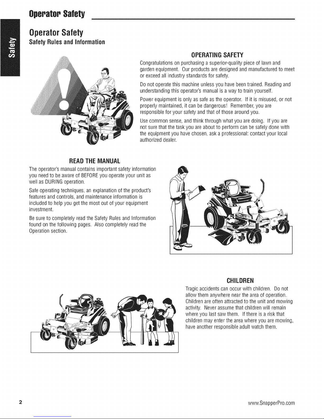
READTHEMANUAL
Theoperator's manual contains important safety information
you need to be awareof BEFOREyou operateyour unit as
well as DURINGoperation.
Safeoperating techniques,an explanation of the product's
featuresand controls, and maintenanceinformation is
included to helpyou get the most out of your equipment
investment.
OPERATINGSAFETY
Be sureto completely readthe Safety Rules and Information
found on the following pages. Also completely read the
Operationsection.
CHILDREN
Tragic accidents canoccur with children. Do not
allow them anywhere near the areaof operation.
Childrenareoften attractedto the unit and mowing
activity. Neverassumethat children will remain
where you lastsaw them. Ifthere is a risk that
children may enter the areawhereyou are mowing,
haveanother responsibleadult watch them.
2 www.SnapperPro.com
Page 5
2O
OperatorSafety
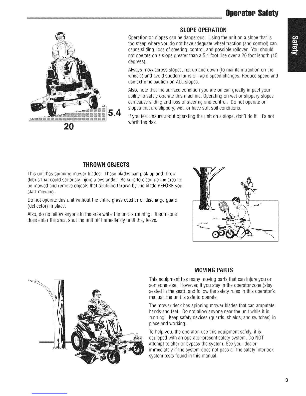
SLOPEOPERATION
Operationon slopes can be dangerous. Using theunit on a slope that is
too steepwhere you do not have adequatewheeltraction (and control) can
cause sliding, loss of steering, control, and possible rollover. You should
not operateon a slope greaterthan a 5.4 foot rise over a 20 foot length (15
degrees).
Always mow across slopes, not up and down (to maintain traction on the
wheels) and avoidsudden turns or rapid speedchanges. Reducespeedand
useextremecaution on ALL slopes.
Also, note that the surface condition you are on can greatly impact your
ability to safelyoperatethis machine. Operatingon wet or slippery slopes
can causesliding and loss of steering and control. Do not operate on
slopes that are slippery, wet, or havesoft soil conditions.
If you feel unsure about operating the unit on a slope, don't do it. It's not
worth the risk.
THROWNOBJECTS
This unit has spinning mower blades. Thesebladescan pick up andthrow
debris that could seriously injure a bystander. Be sure to clean up the areato
be mowed and remove objects that could bethrown by the blade BEFOREyou
start mowing.
Do not operatethis unit without the entire grass catcher or discharge guard
(deflector) in place.
Also, do not allow anyonein the areawhile the unit is running! If someone
does enterthe area,shut the unit off immediately until they leave.
This equipment has many moving parts that can injure you or
someone else. However,if you stay in the operator zone(stay
seated in the seat), and follow the safety rules in this operator's
manual, the unit is safe to operate.
Themower deck has spinning mower bladesthat can amputate
hands and feet. Donot allow anyone near the unit while it is
running! Keepsafety devices(guards, shields,and switches) in
placeandworking.
Tohelpyou, the operator,usethis equipment safely, it is
equipped with an operator-present safety system. Do NOT
attempt to alter or bypassthe system. Seeyour dealer
immediately if the system does not pass all the safety interlock
system tests found in this manual.
lOVING PARTS
Page 6
OperatorSafety
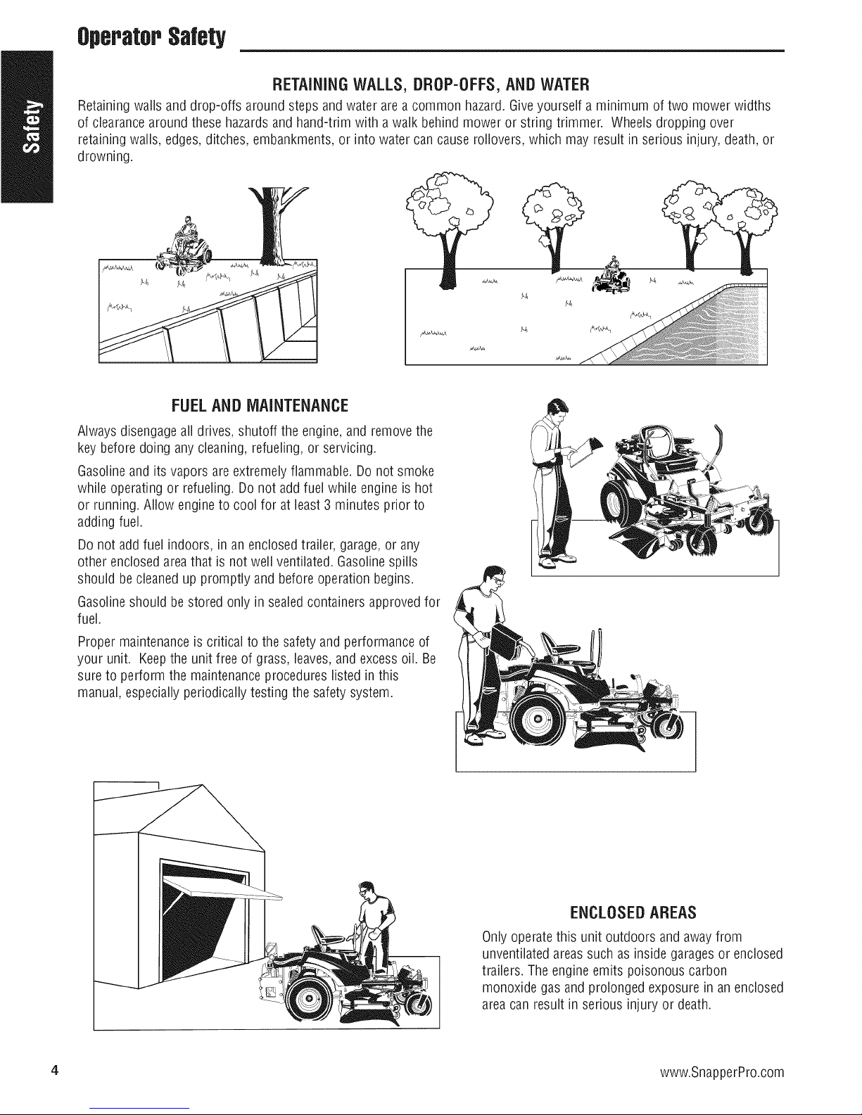
RETAiNiNGWALLS,DROP-OFFS,ANDWATER
Retaining walls and drop-offs around steps and water are a common hazard. Giveyourself a minimum of two mower widths
of clearancearound thesehazardsand hand-trim with a walk behind mower or string trimmer. Wheels dropping over
retaining walls, edges, ditches, embankments,or into water cancause rollovers, which may result in serious injury, death, or
drowning.
FUELAND MAINTENANCE
Alwaysdisengageall drives, shutoff the engine,and removethe
key before doing anycleaning, refueling, or servicing.
Gasolineandits vaporsare extremely flammable. Do not smoke
while operating or refueling. Do not add fuel while engine is hot
or running. Allow engine to cool for at least 3 minutes prior to
adding fuel.
Do not add fuel indoors, in an enclosed trailer, garage,or any
other enclosed areathat is not well ventilated. Gasolinespills
should becleaned up promptly and beforeoperation begins.
Gasolineshould bestored only in sealed containers approvedfor
fuel.
Proper maintenanceis critical to the safety and performance of
your unit. Keepthe unit free of grass, leaves,and excess oil. Be
sure to perform the maintenanceprocedureslisted in this
manual, especiallyperiodically testing the safety system.
4 www.SnapperPro.com
ENCLOSEDAREAS
Only operatethis unit outdoors and away from
unventilated areassuchas inside garagesor enclosed
trailers. The engine emits poisonous carbon
monoxide gas and prolonged exposure in an enclosed
area can result in serious injury or death.
Page 7
OperatorSafety
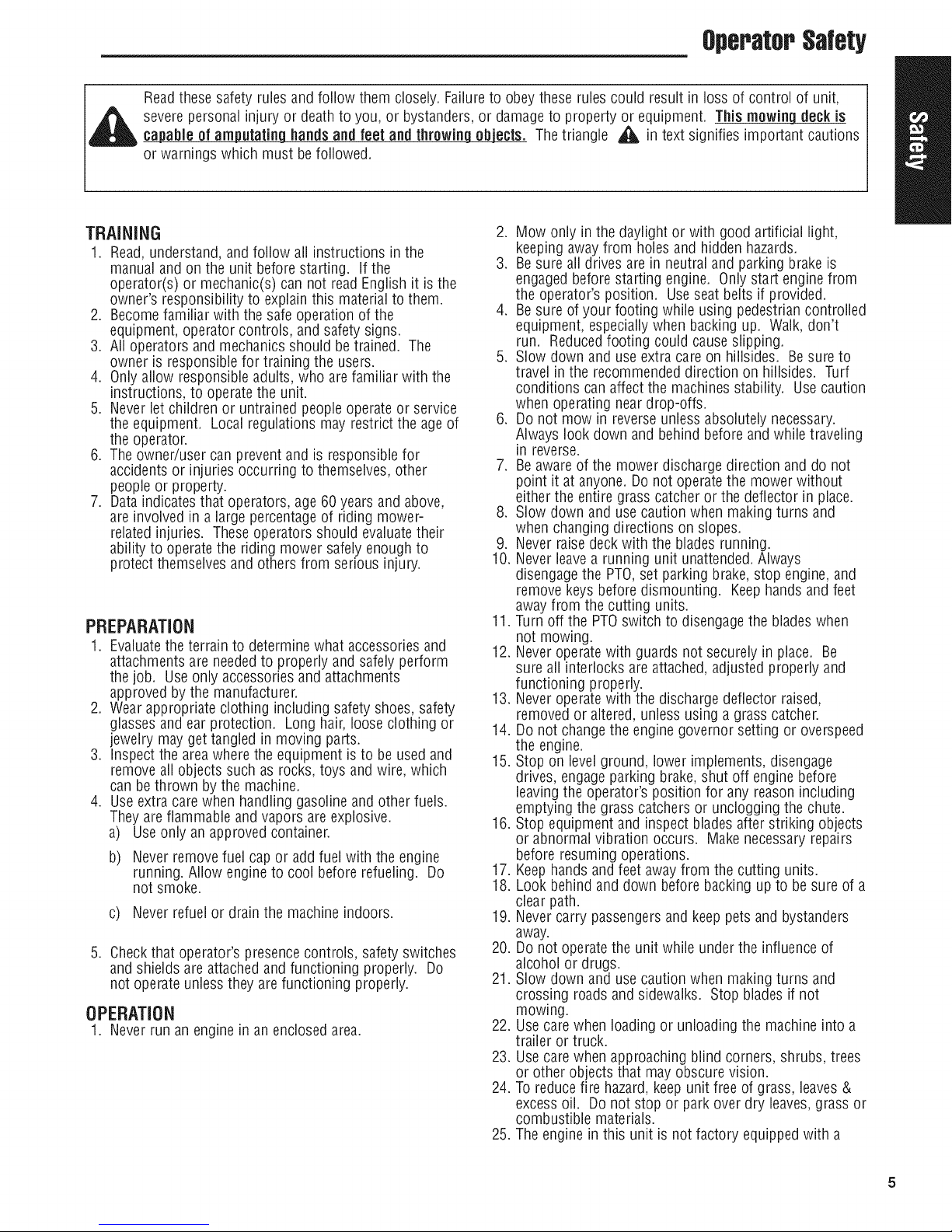
Readthese safety rules and follow them closely. Failureto obey these rulescould result in loss of control of unit,
severe personalinjury or deathto you, or bystanders,or damageto property or equipment. This mewing deck is
capableof amputating hands and feet and throwinq objects. The triangle _ in text signifies important cautions
or warnings which must be followed.
TRAINING
1. Read,understand,and follow all instructions in the
manualandon the unit beforestarting, if the
operator(s) or mechanic(s) can not read English it is the
owner's responsibility to explain this material to them.
2. Becomefamiliar with the safe operation of the
equipment,operator controls, and safety signs.
3. All operators andmechanics should betrained. The
owner is responsiblefor training the users.
4. Onlyallow responsibleadults, who are familiar with the
instructions, to operatethe unit.
5. Neverlet children or untrained peopleoperate or service
the equipment. Localregulations may restrict the age of
the operator.
6. The owner/user can prevent and is responsiblefor
accidentsor injuries occurring to themselves, other
peopleor property.
7. Dataindicatesthat operators, age60 years and above,
are involved in a large percentageof riding mower-
relatedinjuries. Theseoperators should evaluatetheir
ability to operate the riding mower safelyenough to
protect themselvesandothers from serious injury.
PREPARATION
1. Evaluatethe terrain to determine what accessoriesand
attachmentsare neededto properly and safely perform
the job. Useonly accessoriesand attachments
approvedby the manufacturer.
2. Wear appropriate clothing including safety shoes,safety
glassesandear protection. Long hair,looseclothing or
jewelry mayget tangled in moving parts.
3. inspect the areawhere the equipment is to be usedand
remove aii objects such as rocks, toys and wire, which
canbethrown by the machine.
4. Useextra care when handlinggasoline and other fuels.
They are flammable and vapors areexplosive.
a) Useonly an approvedcontainer.
b) Never remove fuel cap or addfuel with the engine
running. Allow engine to cool before refueling. Do
not smoke.
c) Neverrefuel or drain the machine indoors.
5. Checkthat operator's presencecontrols, safety switches
and shields areattachedand functioning properly. Do
not operateunlessthey arefunctioning properly.
OPERATION
1. Neverrun an engine in an enclosed area.
2. Mow only in the daylight or with good artificial light,
keepingawayfrom holes and hidden hazards.
3. Besure all drives are in neutral and parking brakeis
engaged beforestarting engine. Only start engine from
the operator's position. Useseat belts if provided.
4. Besure of your footing while using pedestriancontrolled
equipment, especiallywhen backing up. Walk, don't
run. Reducedfooting could causeslipping.
5. Slow down and use extra care on hillsides. Besure to
travel in the recommendeddirection on hillsides. Turf
conditions can affect the machinesstability. Usecaution
when operating neardrop-offs.
6. Do not mow in reverseunless absolutely necessary.
Always look down and behind beforeand while traveling
in reverse.
7. Beawareof the mower discharge direction and do not
point it at anyone. Do not operate the mower without
either the entiregrass catcher or the deflector in place.
8. Slow down and use caution when making turns and
when changing directions on slopes.
9. Never raisedeckwith the blades running.
10. Neverleave a running unit unattended. Always
disengagethe PTO,set parking brake, stop engine, and
remove keysbefore dismounting. Keephandsand feet
away from the cutting units.
11. Turn off the PTOswitch to disengagethe bladeswhen
not mowing.
12. Neveroperate with guards not securely in place. Be
sure all interlocks are attached, adjusted properly and
functioning properly.
13. Neveroperate with the discharge deflector raised,
removed or altered, unless using a grass catcher.
14. Do not changethe engine governor setting or overspeed
the engine.
15. Stop on levelground, lower implements, disengage
drives, engageparking brake, shut off engine before
leavingthe operator's position for any reason including
emptying the grass catchers or unclogging the chute.
16. Stop equipment and inspect blades after striking objects
or abnormal vibration occurs. Makenecessary repairs
before resuming operations.
17. Keephands and feet awayfrom the cutting units.
18. Look behind and down before backing up to be sure of a
clear path.
19. Nevercarry passengersand keeppets and bystanders
away.
20. Do not operatethe unit while under the influence of
alcohol or drugs.
21. Slow down and usecautionwhen making turns and
crossing roads and sidewalks. Stop blades if not
mowing.
22. Usecare when loading or unloading the machine into a
trailer or truck.
23. Usecare when approaching blind corners, shrubs, trees
or other objects that may obscure vision.
24. To reducefire hazard,keepunit free of grass, leaves&
excess oil. Donot stop or park over dry leaves,grass or
combustible materials.
25. The engine in this unit is not factory equippedwith a
Page 8
OperatorSalety
spark arrester. It is aviolation of California Public
ResourceCode Section 4442 to use or operatethe
engineon or near any forest-covered, brush-covered, or
grass-covered land unlessthe exhaustsystem is
equippedwith a spark arrester meetingany applicable
local or state laws. Other states or federal area may
havesimilar laws.
26.
OSHAregulations may require the use of hearing
protection when exposedto sound levels greaterthan 85
dBAfor an 8 hour time period.
, CAUTION
excessof 85 dBA at the operator's ear and
=_ his machine producessound levels in
cancausehearingloss thoughextended
"J periodsof exposure.
Wear hearingprotectionwhenoperating this machine.
SLOPEOPERATION
Slopesare a majorfactor relatedtoloss-of-controlandtip-
overaccidents,which can resultin severeinjury or death.All
slopes requireextracaution.Ifyou cannot backuptheslope
or if you feel uneasyon it, do not driveon it.
AWARNING
Never operate on slopesgreater than15 degrees which
is a rise of 5.4 feet (165 cm) vertically in 20 feet (607
cm) horizontally.
Select slow ground speedbeforedriving onto slope.
Useextra cautionwhenoperating on slopeswith rear-
mountedgrass catchers.
Mow across the face of slopes,notup and down, use
cautionwhen changingdirections and D0 NOTSTART
ORSTOPONSLOPE.
[}o
1. Mow across slopes, not up and down.
2. Removeobstacles such as rocks, tree limbs, etc.
3. Watch for holes, ruts, or bumps. Uneventerrain could
overturn the unit. Tallgrass can hide obstacles.
4. Useslow speed. Choosea slow speed so that you will
not haveto stop or changespeedwhile on the slope.
5. Useextra care with grass catchers or other attachments.
Thesecan changethe stability of the unit.
6. Keepall movementon the slopes slow and gradual. Do
not make sudden changesin speedor direction.
7. Seeyour authorized dealerfor recommendationsof
availableweights to improve stability.
Do Not
1. Avoid starting, stopping, or turning on aslope, if tires
losetraction (i.e. machine stops forward motion on a
slope), disengage the blade(s) (PTO) and drive slow off
the slope.
2. Do not turn on slopes unless necessary,and then, turn
slowly and gradually uphill, if possible. Nevermow
down slopes.
3. Do not mow near drop-offs, ditches, or embankments.
The operator could lose footing or balanceor mower
could suddenly turn over if a wheel is over the edgeof a
cliff or ditch, or if an edge cavesin.
4. Do not mow on wet grass. Reducedfooting or traction
could causesliding.
5. Do not try to stabilizethe unit by putting your foot on
the ground. (ride-on units)
6. Do not mow excessivelysteep slopes.
7. Do not use grass catcher on steep slopes.
8. Do not mow slopes if you cannot back up them.
TOWED EQUIPMENT (RIDE-ON UNITS)
1. Tow only with a machine that has a hitch designedfor
towing. Donot attachtowed equipmentexcept atthe
hitch point.
2. Follow the manufacturer's recommendationsfor weight
limit for towed equipment and towing on slopes. See
attaching a trailer under OPERATION.
3. Neverallow children or others inor on towed
equipment.
4. Onslopes, the weight of the towed equipment may
cause loss of traction and lossof control.
5. Travelslowly and allow extra distanceto stop.
6. Do not shift to neutral and coast down hill.
CHILDREN
Tragicaccidentscanoccur if the operatoris notalertto the
presenceof children. Childrenareoften attractedto the unit
andthe mowing activity. Neverassumethat childrenwill
remainwhereyou lastsawthem.
1. Keepchildren out of the mowing area and under the
watchful care of another responsible adult.
2. Bealert and turn unit off if children enterthe area.
3. Beforeandduring reverseoperation, look behind and
down for small children.
4. Nevercarry children, even with the blade(s)off. They
may fall off and be seriously injured or interfere with
safe unit operation. Childrenwho have beengiven rides
in the past may suddenly appear in the mowing areafor
another ride and be run over or backedover by the
machine.
5. Neverallow children to operate the unit.
6. Useextra carewhen approaching blind corners, shrubs,
trees, or other objects that may obscure vision.
EMISSIONS
1. Engineexhaustfrom this product contains chemicals
known, in certain quantities, to cause cancer,birth
defects, or other reproductive harm.
2. Look for the relevant Emissions Durability Periodand Air
indexinformationon the engine emissions label.
6 www.SnapperPro.com
IGNITION SYSTEM (GASOLINE MODELS)
1. This spark ignition systemcomplies with Canadian
ICES-O02.
Page 9

OperatorSafety
SERVICEANDMAINTENANCE
Toavoidpersonalin_v or orooertvdamaoe,useextreme
careinhandlincLQasoline.Gasolineisextremelyflammable
andthevaporsareexplosive.
Safe Handlingof Gasoline
1. Extinguishall cigarettes,cigars, pipes, and other
sourcesof ignition.
2. Useonly approvedgasoline containers.
3. Neverremove the gas capor add fuel with the engine
running. Allow the engine to cool before refueling.
4. Neverfuel the machine indoors.
5. Neverstore the machine or fuel container where there is
an open flame, spark, or pilot light such as near a water
heateror other appliance.
6. Neverfiii containers inside a vehicle or on a truck bed
with a plastic bed liner. Always place containers on the
ground awayfrom your vehicle beforefilling.
7. Removegas-powered equipment from the truck or
trailer and refuelit on the ground. If this is not possible,
then refuelsuch equipment on a trailer with a portable
container,rather thanfrom a gasoline dispenser nozzle.
8. Keepnozzlein contact with the rim of the fuel tank or
container opening at all times until fueling is complete.
Donot usea nozzlelock-opendevice.
9. If fuel is spilled on clothing, change clothing
immediately.
10. Neverover-fill the fuel tank. Replacegas capand
tighten securely.
11. Useextra care in handling gasoline and other fuels. They
areflammable and vapors are explosive.
12. If fuel is spilled, do not attempt to start the engine but
move the machine awayfrom the area of spillage and
avoidcreating anysource of ignition until fuel vapors
havedissipated.
13. Replaceall fuel tank caps and fuel container caps
securely.
IVlaintenanceand Storage
1. Always observe safe refueling and fuel handling
practiceswhen refueling the unit after transportation or
storage.
2. Always follow the engine manualinstructions for storage
preparations beforestoring the unit for both short and
long term periods.
3. Always follow the engine manualinstructions for proper
start-up procedureswhen returning the unit to service.
4. Neverstore the machine or fuel container inside where
there is an open flame, such as ina water heater. Allow
unit to cool before storing.
5. Shut off fuel while storing or transporting. Donot store
fuel near flames or drain indoors.
6. Keepall hardware,especiallyblade attachment bolts,
tight and keepall parts in good working condition.
Replaceall worn or damaged decals.
7. Nevertamper with safety devices. Checktheir proper
operation regularly.
8. Disengagedrives, lower implement, setparking brake,
stop engine and remove key or disconnect spark plug
wire. Wait for all movementto stop before adjusting,
cleaningor repairing.
9. Cleangrass and debris from cutting units, drives,
mufflers, and engineto prevent fires. Cleanup oil or
fuel spillage.
10. Letengine cool before storing and do not store near
flame.
11. Stop and inspect the equipment if you strike an object.
Repair,if necessary,before restarting.
12. Parkmachine on levelground. Neverallow untrained
personnelto servicemachine.
13. Usejack stands to support components when required.
14. Carefullyreleasepressure from components with stored
energy.
15. Disconnectbattery or removespark plug wire before
making any repairs. Disconnectthe negativeterminal
first and the positive last. Reconnectpositive first and
negativelast.
16. Usecare when checking blades. Wrap the blade(s) or
wear gloves, and use caution when servicing them.
Only replaceblades. Neverstraighten or weld them.
17. Keephands and feet awayfrom moving parts, if
possible, do not make adjustmentswith the engine
running.
18. Chargebatteries inan openwell ventilated area,away
from spark and flames. Unplug charger before
connecting or disconnectingfrom battery. Wear
protective clothes and useinsulatedtools.
19. Grasscatcher components are subject to wear,damage,
and deterioration, which could expose moving parts or
allow objects to bethrown. Frequentlycheck
components and replacewith manufacturer's
recommendedparts, when necessary.
20. Checkbrake operationfrequently. Adjust and service as
required.
21. Useonly factory authorized replacementpartswhen
making repairs.
22. Always comply with factory specifications on all settings
and adjustments.
23. Onlyauthorized service locations should be utilized for
major service and repair requirements.
24. Neverattempt to makemajor repairs on this unit unless
you havebeen properly trained, improper service
procedures can result in hazardousoperation,
equipment damage and voiding of manufacturer's
warranty.
25. Unitswith hydraulic pumps, hoses,or motors:
WARNING:Hydraulicfluid escapingunder pressure may
havesufficient force to penetrateskin and causeserious
injury. If foreign fluid is injected into the skin it must be
surgically removed within a few hours by a doctor
familiar with this form of injury or gangrenemay result.
Keepbody and hands awayfrom pin holes or nozzles
that eject hydraulic fluid under high pressure. Use paper
or cardboard, and not hands,to search for leaks. Make
sure aii hydraulic fluid connections are tight and all
hydraulic hosesand lines are in good condition before
applying pressureto the system, if leaks occur,have
the unit serviced immediately byyour authorized dealer.
26. WARNING:Stored energydevice, improper releaseof
springs can result in serious personal injury. Springs
should be removedby an authorizedtechnician.
27. Models equipped with an engine radiator: WARNING:
Stored energy device. To prevent serious bodily injury
from hot coolant or steam blow-out, neverattemptto
removethe radiator cap while the engine is running.
Stop the engine and wait until it is cool. Eventhen, use
extreme carewhen removing the cap.
Page 10
,OperatorSafety
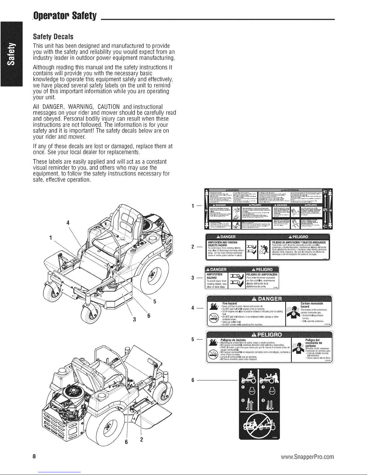
Safety Decals
This unit has beendesigned and manufactured to provide
you with the safety and reliability you would expectfrom an
industry leader in outdoor power equipment manufacturing.
Although readingthis manualand the safety instructions it
contains will provide you with the necessary basic
knowledge to operatethis equipment safely and effectively,
we haveplacedseveral safety labels on the unit to remind
you of this important information while you are operating
your unit.
All DANGER,WARNING, CAUTION and instructional
messageson your rider and mower should be carefully read
and obeyed. Personalbodily injury can result when these
instructions are not followed. The information is for your
safety and it is important! Thesafety decals below are on
your rider and mower.
If any of these decals are lost or damaged, replacethem at
once. Seeyour local dealerfor replacements.
Theselabels areeasily applied andwill act as a constant
visual reminder to you, and others who may usethe
equipment, to follow the safety instructions necessaryfor
safe,effective operation.
1 m
OBJECTS HAZARD =_ Papaev_ar SLff[_; les or_escausadas por I_s c?ch_llas
IAOPOTA"OOA"OTR OW°I I I O0000EAOPOOO'ON'OOJE'OSA"" AOOS
2 -- ill avoid in ury from rotat rig blades _ ".,_ glralor as y oberos la izades, ma_lier!_rse ale ado del horde
s ay cea _ deck eSge and keeg o e s /_;: de la }lataforuFa de cone y T_anfener a Ins demos personas
i o , , ,_ b izlJi.:.'_::_--I..................................................
" Y g _ :--_'_ d ca g I _ed de p i e I ga
AMPUTATION _--_-_._ PEMORODEAMPUTACION
3 -- HAZARD _ Paraevitarlesionescausadas
4 m
5 m
.....................i..........................
8 www.SnapperPro.com
6 2
Page 11

Safety interlockSystem
This unit is equippedwith safety interlock switches. These
safety systems are presentfor your safety,do not attempt
to bypasssafety switches, and nevertamper with safety
devices. Checktheir operation regularly.
OperatorSafety
Safety icons
Thealert symbol _ is usedto identity safety information
about hazardsthat can result in personalinjury. A signal
word (DANGER,WARNING,or CAUTION)is used with the
alert symbol to indicate the likelihood and the potential
severity of the injury. In addition, a hazard icon may be
usedto representthe type of hazard. An explanationof
hazardlevelsand icons are as follows:
Operational SAFETYChecks
Test1 -- EngineshouldNOTcrankif:
* PTOswitch is engaged, OR
. Parkingbrake is not engaged,OR
. Groundspeedcontrol leversare not in the NEUTRAL
position.
Test2 -- Engine SHOULDcrankif:
. PTOswitch is NOTengaged,AND
. Parkingbrake is engaged,AND
. Groundspeedcontrol leversare locked in the NEUTRAL
position.
Test3 -- EngineshouldSHUT OFFif:
* Operatorrisesoff seatwith PTOengaged,OR
. Operatorrises off seatwith parking brakedisengaged.
. Operatormoves ground speed control leversout of
their neutral positions before disengagingparking
brake.
Test4 = Blade BrakeCheck
Mower blades and mower drive belt should cometo a
complete stop within seven (7) seconds after electric PTO
switch is turned off (or operator rises off seat). If mower
drive belt does not stop within seven (7) seconds, seeyour
dealer.
NOTE.Once the enginehas stopped, PTOswitch must be
turned off, parking brake must be engaged,and the motion
control handlesmust be locked in the NEUTRALposition
after the operator returns to the seat in order to start the
engine.
AWARNING
DANGER
This indicates a hazardwhich, if not avoided, will result in
seriousinjuryor death.
WARNING
This indicates a hazardwhich, if not avoided, could result in
serial injuryor death.
,A CAUTION
This indicates a hazardwhich, if not avoided, might result in
minor or moderate injury.
CAUTIONor NOTICE
Thesemessagespresented without the alert symbol indicate
a situation where the unit or property could be damaged.
NorthAmerican Safety icons
Hazard
Alert
Toxic Fumes
Read the
Manual
Open Flame
Hazard
Fire Hazard
Safety Icon
A
@
Hazard
Amputation
Foot in Blade
Maintain a
Safe
Distance
Keep
Children
Away
HotSurface
iSafety icon
0
o
if the unitdoes not pass a safetytest, do not operate
it. See yourauthorized dealer. Under no
circumstanceshouldyouattempt to defeat thepurpose
of the safetyinterlocksystem.
Amputation
Rotating
Parts
Amputation
Handin
Blade
Rollover
Hazard
Wear
Protective
Gear
PinchPoint
Overhead
Obstacles
0
9
Page 12
FeaturessndControls
FeaturesandControls
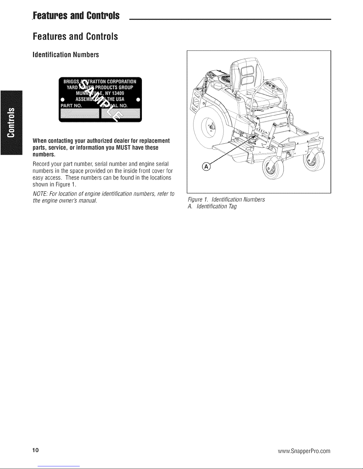
identificationNumbers
Whencontacting your authorizeddealer for replacement
parts, service,or informationyou MUSThavethese
numbers.
Record your part number, serial number and engine serial
numbers in the space provided on the inside front cover for
easy access. Thesenumbers can be found in the locations
shown in Figure1.
NOTE.For location of engineidentification numbers, refer to
the engineowner's manual.
Figure 1. Identification Numbers
A. Identification Tag
10 www.SnapperPro.com
Page 13
FeaturessndControls
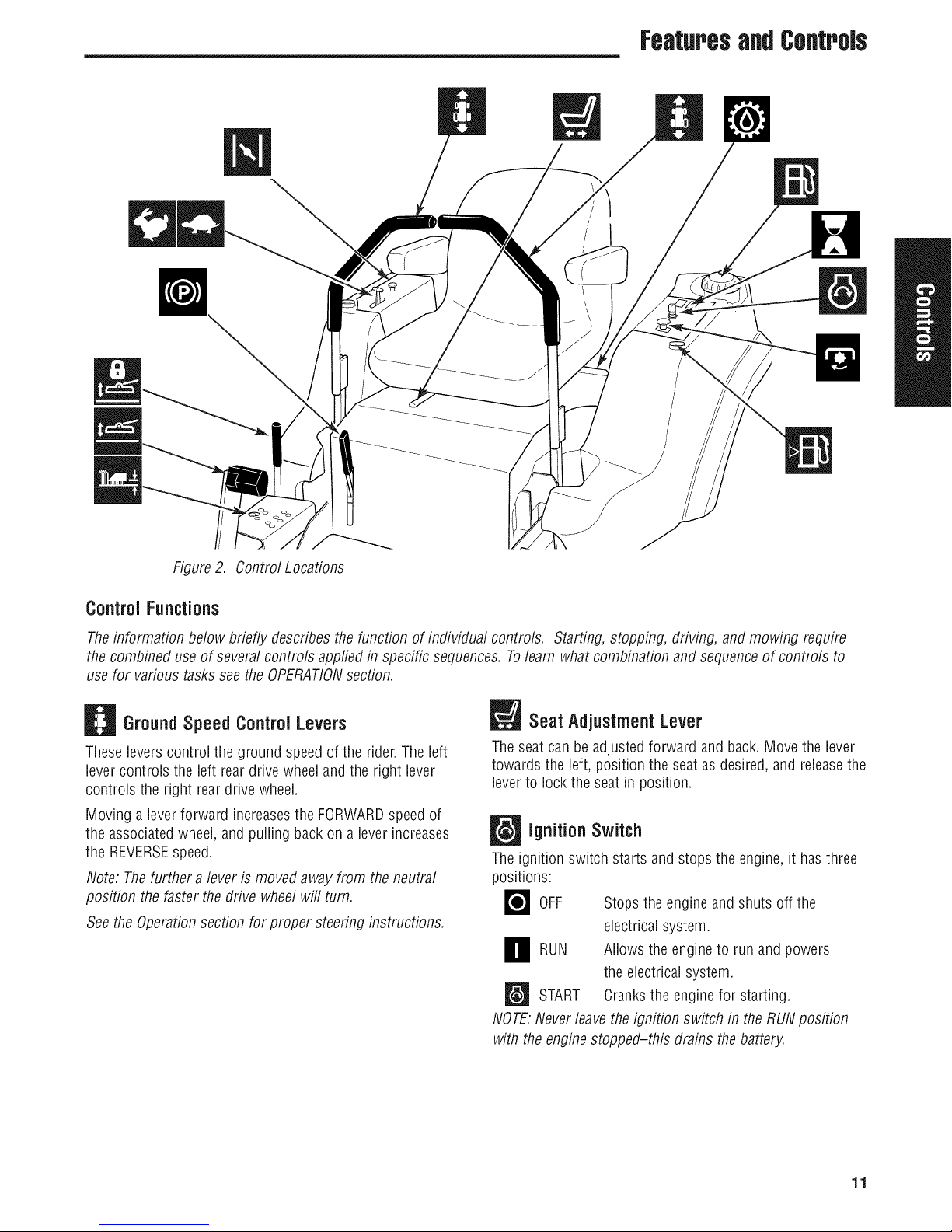
Figure2. Control Locations
ControlFunctions
Theinformation below briefly describes the function of individual controls. Starting, stopping, driving, and mowing require
the combined use of several controls appfiedin specific sequences. Tolearn what combination and sequenceof controls to
use for various tasksseethe OPERATIONsection.
GroundSpeed Control Levers
Theselevers control the ground speedof the rider.The left
lever controls the left rear drive wheeland the right lever
controls the right rear drive wheel.
Moving a leverforward increasesthe FORWARDspeedof
the associatedwheel, and pulling back on a lever increases
the REVERSEspeed.
Note: Thefurther a lever is moved away from theneutral
position the faster the drive wheelwill turn.
See the Operationsection for proper steering instructions.
Seat Adjustment Lever
Theseatcan be adjusted forward and back.Move the lever
towards the left, position the seat as desired, and releasethe
leverto lock the seat in position.
IgnitionSwitch
Theignition switch starts and stops the engine, it has three
positions:
_OFF Stops the engine and shuts off the
electrical system.
O RUN Allows the to and
the electrical system.
_'_ START Cranks the engine for starting.
NOTE.Neverleave the ignition switch in theRUNposition
with the enginestopped-this drains thebattery.
engine
run
powers
11
Page 14

Features& Controls
_ ParkingBrake
_ DISENGAGE
ENGAGE
Pull the parking brake lever up to engagethe parking brake.
Push the leverdown to disengagethe parking brake. NOTE.
Tostart the unit theparking brakemust be engaged.
_PTO (Power Take Off) Switch
The PTOswitch engagesand disengagesthe mower. Pull UP
on the switch to engage,and push DOWNto disengage.
Releasesthe parking brake.
Locks the parking brake.
DeckLift Pedal, Cutting Height
Adjustment Pin & DeckLift Lock
Lever
Thesecontrol the cutting height of the mower deck.
Depressthe pedaluntil it locks into the 4-1/2" (11,47 cm)
position. Placethe adjustment pin in the desired cutting
height and releasethe lift lock lever.
FuelTankCap
To removethe cap, turn counterclockwise.
FuelLevel Gauge
Displaysthe fuel level in the tank.
TransmissionOil Fill
This unit is equippedwith two transmission oil reservoirs.
Thetransmission oil reservoirs are located beneaththe
operator's seat and in front of the engine. Transmission oil
is added through the transmission oil reservoirs. It also
servesas extraholding capacityas the transmissions heat
up and the oil expands. SeeCHECKTRANSMISSIONOIL
LEVELfor oil levelcheckandfill procedures.
ThrottleControl
Thethrottle controls engine speed. Movethe throttle
forward to increaseengine speed and back to decrease
engine speed. Always operateat FULLthrottle.
W Choke
Closethe choke for cold starting. Openthe choke oncethe
engine starts. A warm engine may not require choking. Pull
the knob UPto close the choke. Push to knob DOWNto
open the choke.
B HourMeter / MaintenanceReminder
Measuresthe time of the PTObeing engaged. The hour
meter measuresthe number of hours the PTOhas been
engaged. The hour meterwill flash an initial oil change
indicator at 5 hours, and a lubrication reminder every50
hours. These reminders display for approximately two
hours andwill automatically reset themselves.
Note: Thehour meter wilt register thepassageof time only
whenthe PTOis engaged. Thehour meter has a self
contained power source so the total hours arealways
visible.
12 www.SnapperPro.com
Page 15
Operation
Operation
GeneralOperating Safety
Beforefirst time operation:
• Besure to read all information in the Safetyand
Operationsectionsbefore attempting to operatethis
tractor and mower.
• Becomefamiliar with all of the controls and how to stop
the unit.
• Drive in an open areawithout mowing to become
accustomedto the unit.
WARNING
Never allow passengersto rideon the unit.
Beforeleavingthe operator's positionfor any reason,
engage the parkingbrake, disengage the PTO,stopthe
engine and removethe key.
Toreducefire hazard, keepthe engine, tractor and
mowerfree of grass, leaves and excess grease. Do not
stopor parktractor over dry leaves, grass or
combustiblematerials.
Gasolineis highly flammable and mustbe handled
with care. Never fill the tank whenthe engine is still
hotfrom recentoperation. Do notallow open flame,
smokingor matchesin the area. Avoid over-filling and
wipe up any spills.
WARNING
WARNING
Never operate on slopesgreater than (15°) whichisa
riseof 5.4 feet (1,6 m) vertically in20 feet (607 cm)
horizontally.
Select slow ground speed beforedriving onto a slope.
Useextra cautionwhen operating on slopeswith a
rear-mountedgrass catcher.
Mowacross the face of slopes,notup and down, use
cautionwhen changingdirections and DO NOTSTART
ORSTOPONSLOPE.
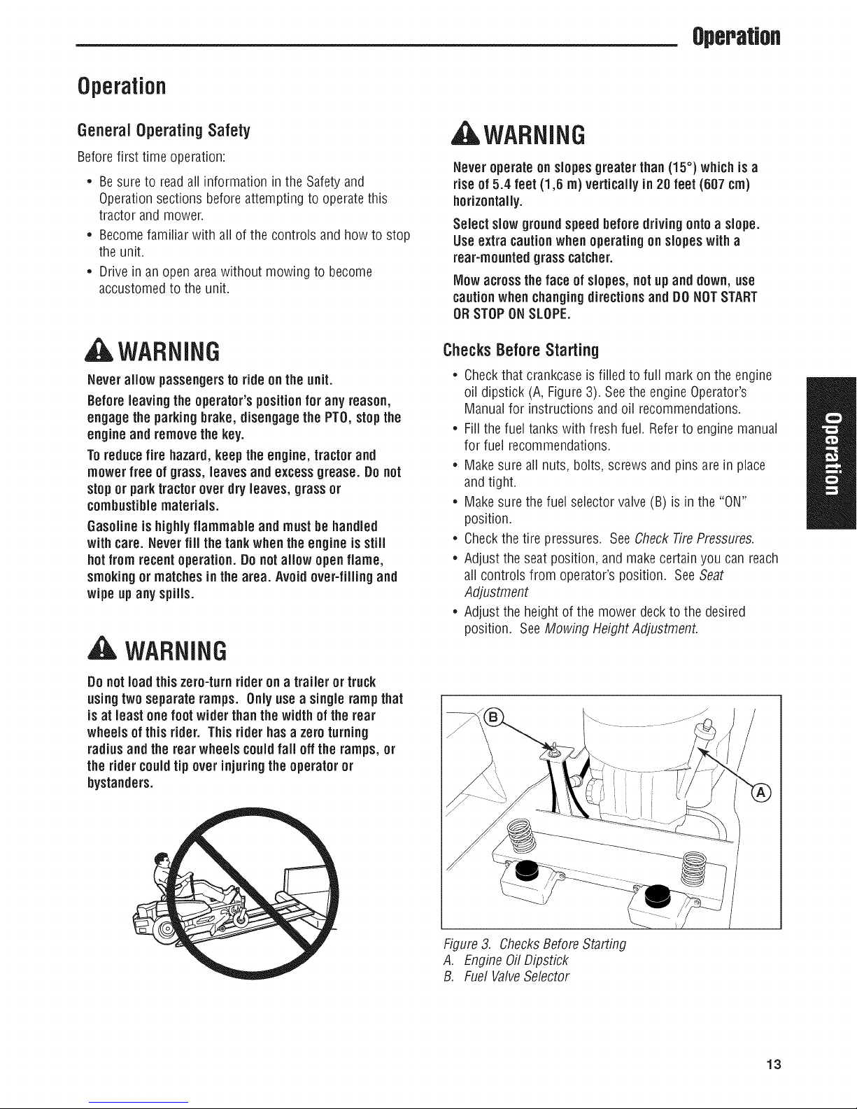
ChecksBeforeStarting
• Checkthat crankcaseis filled to full mark on the engine
oil dipstick (A, Figure 3). Seethe engine Operator's
Manualfor instructions and oil recommendations.
• Fillthe fuel tanks with fresh fuel. Referto engine manual
for fuel recommendations.
• Makesure all nuts, bolts, screws and pins are in place
and tight.
• Makesure the fuel selectorvalve(B) is in the "ON"
position.
• Checkthe tire pressures. See CheckTire Pressures.
• Adjust the seatposition, and make certain you can reach
all controls from operator's position. SeeSeat
Adjustment
• Adjust the height of the mower deckto the desired
position. See Mowing Height Adjustment.
Do notload this zero-turn rider on a trailer or truck
usingtwo separateramps. Only useasingle rampthat
is at least one foot widerthan the widthof the rear
wheels of this rider. This rider hasazero turning
radiusand the rear wheels couldfall off the ramps, or
the ridercouldtip over injuringthe operator or
bystanders.
Figure3. ChecksBefore Starting
A. EngineOil Dipstick
B. Fuel ValveSelector
13
Page 16

Operatm
CheckTire Pressures
Tire pressure should be checkedperiodically, and
maintained at the levels shown in the chart. Note that these
pressures may differ slightly from the "Max Inflation"
stamped on the side-wall of the tires. Thepressures shown
provide proper traction, improve cut quality, and extend tire
life.
Tire Pressure
Front 40 psi (2,76 bar)
Rear 15 psi (1,03 bar)
Seat Adjustment
SeeFigure5. The seatcan be adjusted forward and
backward. Move the lever towards the left, position the seat
as desired, and releasethe lever to lock the seat into
position.
Figure4. CheckingTirePressure
Figure5. SeatAdjustment
A. SeatAdjustment Lever
14 www.SnapperPro.com
Page 17
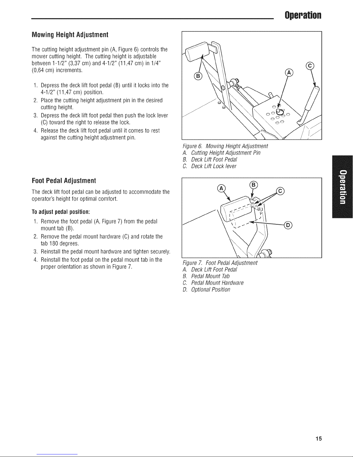
Mowing HeightAdjustment
Thecutting height adjustment pin (A, Figure6) controls the
mower cutting height. The cutting height is adjustable
between 1-1/2" (3,37 cm) and 4-1/2" (11,47 cm) in 1/4"
(0,64 cm) increments.
1. Depressthe deck lift foot pedal (B) until it locks into the
4-1/2" (11,47 cm) position.
2. Placethe cutting height adjustment pin in the desired
cutting height.
3. Depressthe deck lift foot pedalthen push the lock lever
(C)toward the right to releasethe lock.
4. Releasethe deck lift foot pedal until it comes to rest
againstthe cutting height adjustment pin.
FootPedalAdjustment
Operation
Figure 6. Mowing Height Adjustment
A. Cutting HeightAdjustment Pin
B. Deck Lift Foot Pedal
C. Deck Lift Lock lever
Thedeck lift foot pedalcan be adjusted to accommodate the
operator's height for optimal comfort.
Toadjust pedalposition:
1. Removethe foot pedal (A, Figure7) from the pedal
mount tab (B).
2. Removethe pedalmount hardware (C) and rotatethe
tab 180 degrees.
3. Reinstallthe pedalmount hardware and tighten securely.
4. Reinstallthe foot pedalon the pedal mount tab in the
proper orientation as shown in Figure7.
Figure 7. Foot PedalAdjustment
A. Deck Lift Foot Pedal
B. Pedal Mount Tab
C. Pedal Mount Hardware
D. Optional Position
15
Page 18

OperaUon
Starting the Engine
AWARNING
if youdo notunderstandhowa specificcontrol
functions, or havenotyet thoroughlyreadthe
FEATURES& CONTROLSsection, do sonow.
Do NOTattempt tooperate thetractorwithout first
becomingfamiliar with the locationandfunction ofALL
controls.
1. While sitting in the operator's seat, engagethe parking
brakeby pulling the parking brakelever up, make sure
the PTOswitch is disengaged (pressed down fully) and
the ground speedcontrol levers are locked in the
NEUTRALposition.
2. NOTE:A warm engine may notrequire choking.
Setthe enginethrottle control to FULLthrottle position.
Thenfully close the choke by pulling the knob OUTfully.
3. insert the key into the ignition switch and turn it to
START.
4. After the engine starts, gradually open the choke (push
knob down fully). Reduceto half throttle speed and
allow to warm up.
Warm up the engineby running it for at least a minute
before engaging the PTOswitch or driving the rider.
5. After warming the engine, ALWAYSoperate the unitat
FULLTHROTTLEwhen mowing.
In the event of an emergencythe enginecan fie stopped
bysimply turning the ignition switch to STOP. Usethis
method only in emergencysituations. Fornormal engine
shut down follow the procedure given in STOPPINGTHE
RIDER.
Pushingthe Rider ByHand
NOTICE
DONOTTOW RIDER
Towingthe unitswill causetransmissiondamage. Do
notuse another vehicleto pushor pull this unit.
1. Disengagethe PTO,engagethe parking brake,turn the
ignition OFEand removethe key.
2. Locatethe transmission releaselevers (A, Figure8)
located underneaththe front of the fuel tanks.
3. Pull both transmission releaselevers back and down so
that they lock inthe disengaged(free-wheel position)
(c).
4. Disengagethe parking brake.
Thetractor cannow be pushed by hand.
5. After moving the tractor, re-engagethe transmissions by
pulling the transmission releaseleversup andpushing
them forward to the engaged (drive) position (B).
Stopping the Rider
1. Returning the ground speedcontrol leversto the middle
position will stop rider movement. Pivot the levers
outward and lockthem in NEUTRAL.
2. Disengagethe PTOby pushing down on the PTOswitch.
3. Engagethe parking brakeby pulling the handleup until
it locksinto position.
4. Move the throttle control to mid-throttle position and
turn the ignition keyto OFF. Removethe key.
16 www.SnapperPro.com
Figure 8. TransmissionReleaseLevers(LH shown)
A. TransmissionReleaseLever
B. EngagedPosition (Drive Position)
C. DisengagedPosition (Free-wheelPosition)
Page 19
Operation
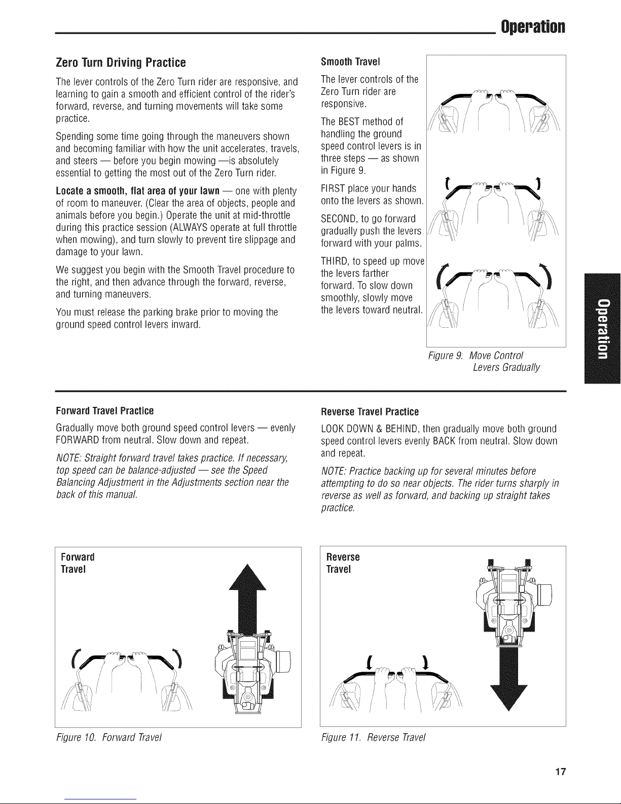
Zero TurnDrivingPractice
Thelever controls of the ZeroTurn rider are responsive,and
learning to gain a smooth and efficient control of the rider's
forward, reverse,and turning movementswill take some
practice.
Spending some time going through the maneuversshown
and becoming familiar with how the unit accelerates,travels,
and steers-- beforeyou begin mowing --is absolutely
essentialto getting the most out of the Zero Turn rider.
Locatea smooth,fiat area of yourlawn-- one with plenty
of room to maneuver.(Clearthe area of objects, peopleand
animals beforeyou begin.) Operatethe unit at mid-throttle
during this practice session (ALWAYSoperateat full throttle
when mowing), and turn slowly to preventtire slippageand
damageto your lawn.
Wesuggest you beginwith the Smooth Travelprocedureto
the right, andthen advancethrough the forward, reverse,
and turning maneuvers.
You must releasethe parking brake prior to moving the
ground speed control levers inward.
Smooth TraveJ
Thelever controls of the
ZeroTurn rider are
responsive.
The BESTmethod of
handling the ground
speedcontrol levers is in
three steps-- as shown
in Figure 9.
FIRSTplaceyour hands
onto the levers as shown.
SECOND,to go forward
gradually push the levers
forward with your palms.
THIRD,to speed up move
the levers farther
forward. Toslow down
smoothly, slowly move
the levers toward neutral.
Forward TraveJPractice
Graduallymove both ground speedcontrol levers-- evenly
FORWARDfrom neutral. Slow down and repeat.
NOTE.Straight forward travel takespractice. If necessary,
top speedcan be balance-adjusted-- seethe Speed
BalancingAdjustment in theAdjustments section near the
back of this manual.
Forward
Travel
Figure9. Move Control
Levers Gradually
ReverseTravelPractice
LOOKDOWN& BEHIND,then graduallymove both ground
speedcontrol levers evenly BACKfrom neutral. Slow down
and repeat.
NOTE.Practicebacking up for severalminutes before
attempting to do so near objects. The rider turns sharplyin
reverseas weftas forward, and backing up straight takes
practice.
Reverse
Travel
Figure 10. Forward Travel Figure 11. ReverseTravel
/
/'
/
17
Page 20
OperaUon
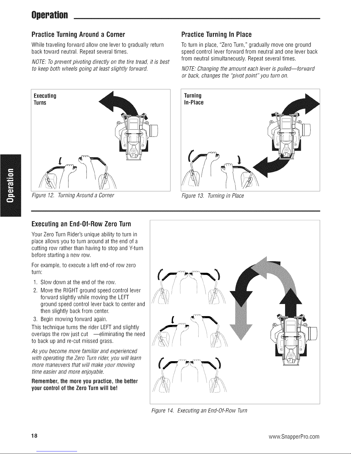
Practice TurningAround a Corner
While traveling forward allow one leverto gradually return
back toward neutral. Repeatseveral times.
NOTE:Topreventpivoting directly on the tire tread,it is best
to keepboth wheelsgoing at least slightly forward.
Figure 12. TurningAround a Corner
Practice Turningin Place
Toturn in place, "Zero Turn," gradually move one ground
speedcontrol lever forward from neutraland one leverback
from neutral simultaneously. Repeatseveraltimes.
NOTE.Changingtheamount eachlever is puffed--forward
or back, changes the "pivot point" you turn on.
Turning
In-Place
Figure 13. Turningin Place
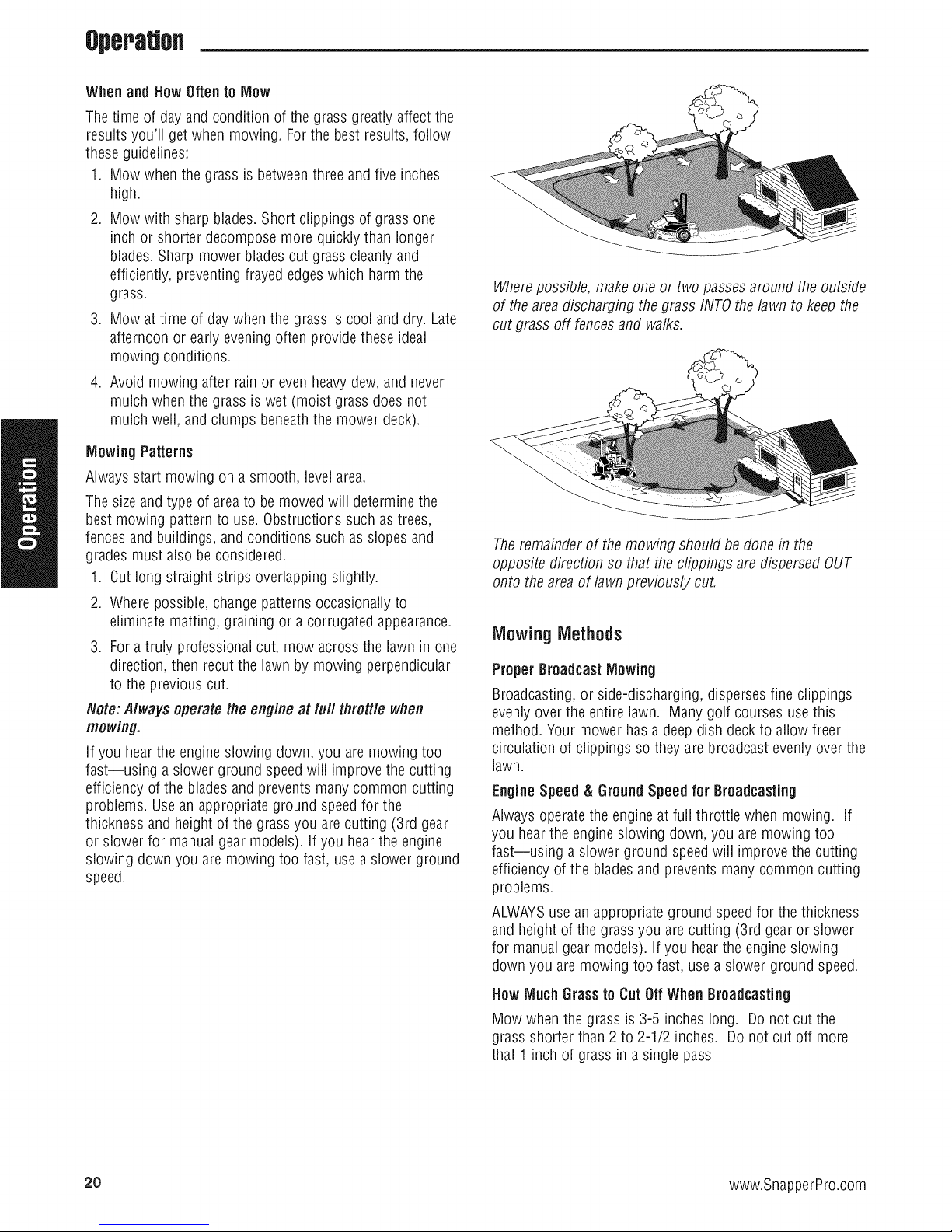
Executingan End-Of-RowZeroTurn
Your ZeroTurn Rider's unique ability to turn in
placeallows you to turn around at the endof a
cutting row rather than having to stop and Y-turn
before starting a new row.
For example,to executealeft end-of row zero
turn:
1. Slow down at the end of the row.
2. Move the RIGHTground speedcontrol lever
forward slightly while moving the LEFT
ground speed control lever back to center and
then slightly backfrom center.
3. Begin mowing forward again.
This technique turns the rider LEFTand slightly
overlaps the row just cut --eliminating the need
to back up and re-cut missed grass.
Asyou become more familiar and experienced
with operating the Zero Turn rider,you will learn
more maneuversthat will makeyour mowing
time easier and more enjoyable.
Remember, the moreyou practice, the better
yourcontrol of the Zero Turnwill be!
18 www.SnapperPro.com
Figure 14. Executing an End-Of-Row Turn
Page 21

Operation
Mowing
1. Engagethe parking brake. Make sure the PTOswitch is
disengaged,the ground speedcontrol leversarelocked
in the NEUTRALposition and the operator is on the seat.
2. Start the engine (see Starting The Engine).
3. Setthe mower cutting height (see Mowing Height
Adjustment).
4. Setthe throttle to FULL.
5. Engagethe PTOby pulling up on the PTOswitch.
6. Begin mowing. See Mowing Recommendationsfor tips
on mowing patterns, lawn care, and trouble shooting
information.
7. When finished, shut off the PTOby pushing the PTO
switch down completely_
8. Stopthe engine (seeStopping TheRiderand Engine).
Mowing Recommendations
Severalfactors can affect how wenyour machine cuts grass,
Following proper mowing recommendations canimprove
the performance and life of your machine.
Heightof Grass
Often cutting height is a matter of personal preference.
Typically,you should mow the grass when it is is between
three and five inches high. The proper cutting height range
for a specific lawn will depend upon several factors,
including thetype of grass,the amount of rainfall, the
prevailing temperature, and the lawn's overall condition.
Cutting the grass too short causesweak,thin grass plants,
which are easily damaged by dry periods and pests. Cutting
too short is often more damaging than allowing the grassto
be slightly higher.
Letting grass grow a bit Ionger--especiaNy when it is hot
and dry--reduces heat build-up, preservesneededmoisture
and protects the grass from heatdamageand other
problems. However,allowing grass to grow too high can
causethin turf and additional problems.
Cutting off too much at onetime shocksthe plant's growth
system and weakensthe grass plants.A good rule of thumb
is the1/3 rule: to cut no more thanone third of the grass
height, and nevermore than1 inchat a time.
Theamount of grass you are able to cut in one pass is also
effected by the type of mowing system you are using (for
example,broadcasting with side discharge decks can
process a much larger volume of grass than mulching
does).
I
,li i.iILl4<,it,,/',
t! I
Figure 15. Proper Cutting Height
Tail GrassRequires Incremental Cutting
Forextremelytall grass, set the cutting height at maximum
for the first pass, and then reset it to the desired height and
mow a second or third time.
Don't cover the grass surfacewith a heavy layerof
clippings. Consider using a grass collection system and
starting a compost pile.
Cut Here On
First Pass Cut Here
Is ,/ Pass
IItlih,l ltlilt
Figure 16. Incremental Cutting
On Second
19
Page 22
Operatm
Whenand How Often to Mow
Thetime of day and condition of the grass greatly affectthe
results you'll get when mowing. Forthe best results, follow
these guidelines:
1. Mow when the grass is betweenthree and five inches
high.
2. Mow with sharp blades. Short clippings of grassone
inchor shorter decomposemore quickly than longer
blades.Sharp mower blades cut grass cleanly and
efficiently, preventing frayed edgeswhich harm the
grass.
3. Mow at time of day when the grass is cool and dry. Late
afternoon or early eveningoften provide these ideal
mowing conditions.
4. Avoid mowing after rain or evenheavy dew,and never
mulch when the grass is wet (moist grass does not
mulch well, and clumps beneaththe mower deck).
Mowing Patterns
Alwaysstart mowing on a smooth, level area.
Thesizeand type of areato be mowed wiii determine the
best mowing pattern to use. Obstructions such astrees,
fencesand buildings, and conditions such as slopes and
grades must also be considered.
1. Cut long straight strips overlapping slightly.
2. Where possible, change patterns occasionally to
eliminate matting, graining or a corrugated appearance.
3. Foratruly professional cut, mow across the lawn in one
direction, then recut the lawn by mowing perpendicular
to the previous cut.
Note:A/ways operate the engine at fu// tflrott/e when
mowing.
If you hearthe engine slowing down, you are mowing too
fast--using a slower ground speedwill improve the cutting
efficiency of the bladesand prevents many common cutting
problems. Usean appropriate ground speed for the
thickness and height of the grass you are cutting (3rd gear
or slower for manualgear models), if you hear the engine
slowing down you are mowing too fast, useaslower ground
speed.
Wherepossible, make one or two passesaround the outside
of the areadischarging the grass INTOthe lawn to keep the
cut grass off fences and walks.
Theremainderof the mowing should be done in the
opposite direction so that the clippings are dispersed OUT
onto the areaof lawn previously cut.
MowingMethods
Proper Broadcast Mowing
Broadcasting,or side-discharging, disperses fine clippings
evenly overthe entire lawn. Manygolf courses use this
method. Your mower has a deep dish deck to allow freer
circulation of clippings so they are broadcast evenlyover the
lawn.
Engine Speed & GroundSpeed for Broadcasting
Always operatethe engineat full throttle when mowing. If
you hear the engine slowing down, you are mowing too
fast--using a slower ground speedwill improve the cutting
efficiency of the bladesand prevents many common cutting
problems.
ALWAYSusean appropriate ground speedfor the thickness
and height of the grass you are cutting (3rd gear or slower
for manualgear models). If you hearthe engine slowing
down you are mowing too fast, use a slower ground speed.
20 www.SnapperPro.com
How Much Grassto Cut Off When Broadcasting
Mow when the grass is 3-5 incheslong. Do not cut the
grass shorter than 2 to 2-1/2 inches. Donot cut off more
that 1 inchof grass in a single pass
Page 23
Operation
ProperMulching
Mulching consists of a mower deckwhich cuts and recuts
clippings intotiny particles and which then blows them
down iNTOthe lawn. These tiny particles decompose rapidly
into by-products your lawn can use. UNDERPROPER
CONDITIONS,your mulching mower will virtually eliminate
noticeable clippings on the lawn surface.
NOTE:When mulching under heavycutting conditions, a
rumbling sound may bepresent and is normal.
IVluichingRequires EXCELLENTMowing Conditions
Mulching mowers cannot function properly if the grass is
wet, or if the grass is simply to high to cut. Evenmore than
normal mowing, mulching requires that the grass be dry
and the the appropriate amount is cut.
Do not usethe mower as a mulching mower during the first
two or three mowings in the spring. Thelong grass blades,
quick growth, and often wetter conditions are more suitable
for broadcasting (side-discharging) or grass bagging
operation.
Engine Speed & GroundSpeed for Mulching
Usefuji enginethrottle matchedwith a slow ground speed
so that clippings will be finely cut. Ground speedwhile
mulching should be HALFof the speedthat would be used
when broadcasting (side discharging) under similar
conditions. Since mulching requires more horsepowerthan
broadcasting, using a slower ground speedis vitally
important for proper mulching operation.
Row Much Grassto Mulch
Thebest mulching action typically results from cutting only
the top 1/2 inch to 3/4 inch of grass blade. This provides
short clippings which decomposeproperly (much more
quickly than longer clippings). The ideal cutting height will
vary with climate, time of year, and quality of your lawn. We
recommend that you experiment with both the cutting height
and ground speed until you achievethe best cut. Start with a
high cutting height and using progressivelylower settings
until you find a cutting height that is matchedto your
mowing conditions and preferences.
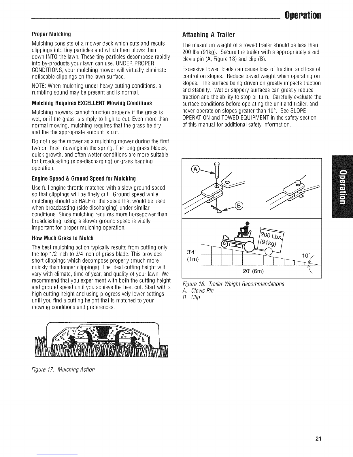
Attaching A Trailer
Themaximum weight of a towed trailer should be less than
200 Ibs (91kg). Secure the trailer with a appropriately sized
clevis pin (A, Figure18) and clip (B).
Excessivetowed loads cancause loss of traction and loss of
control on slopes. Reducetowed weight when operating on
slopes. The surface being driven on greatlyimpacts traction
and stability. Wet or slippery surfaces can greatly reduce
traction and the ability to stop or turn. Carefullyevaluatethe
surface conditions beforeoperating the unit and trailer, and
neveroperateon slopes greaterthan 10°. SeeSLOPE
OPERATIONand TOWEDEQUIPMENTin the safety section
of this manualfor additional safety information.
®
3'4"
(lm)
20' (6m) ?
Figure 18. TrailerWeightRecommendations
A. Clevis Pin
B. Clip
Figure 17. Mulching Action
21
Page 24
RegWPMaJflteflaflce
RegularMaintenance
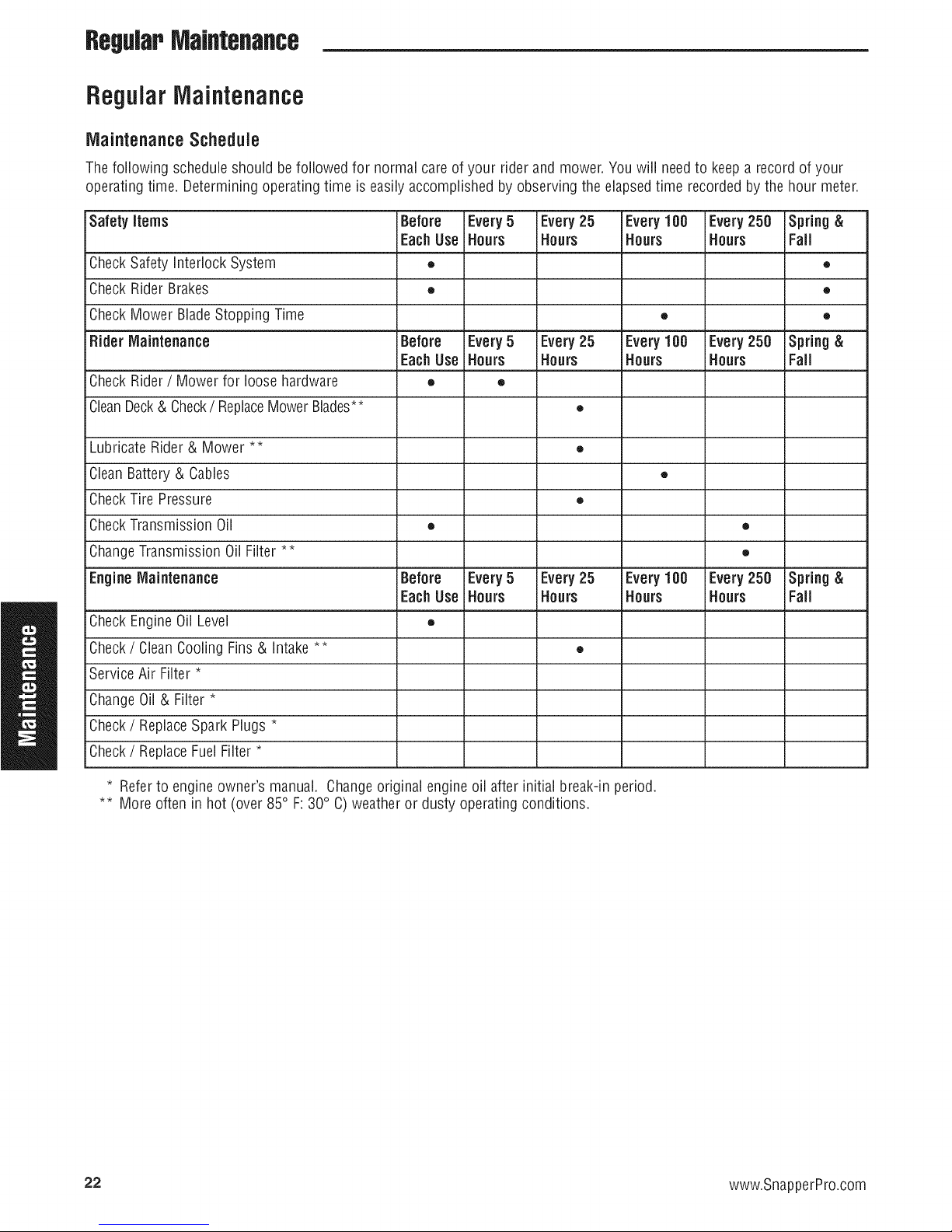
MaintenanceSchedule
Thefollowing schedule should be followed for normal care of your rider and mower.You will needto keepa record of your
operating time. Determiningoperating time is easily accomplished by observing the elapsedtime recorded bythe hour meter.
Safety items Before Every5 Every25 Every100 Every250 Spring &
EachUse Hours Hours Hours Hours Fall
CheckSafetyInterlock System • •
CheckRider Brakes • •
CheckMower BladeStopping Time • •
Hider Maintenance Before Every5 Every25 Every100 Every250 Spring &
EachUse Hours Hours Hours Hours Fall
CheckRider/ Mower for loose hardware • •
CleanDeck& Check/ ReplaceMower Blades** •
Lubricate Rider& Mower ** •
CleanBattery& Cables •
CheckTire Pressure •
CheckTransmission Oil • •
ChangeTransmission Oil Filter ** •
EngineMaintenance Before Every5 Every25 Every100 Every250 Spring &
EachUse Hours Hours Hours Hours Fall
CheckEngineOil Level •
Check/ CleanCooling Fins& intake ** •
Service Air Filter *
ChangeOil& Filter *
Check/ ReplaceSpark Plugs *
Check/ ReplaceFuelFilter *
• Referto engine owner's manual. Changeoriginal engine oil after initial break-in period.
•* More often in hot (over 85° F: 30° C)weather or dusty operating conditions.
22 www.SnapperPro.com
Page 25
RegWPMaJflteflaflce
Checking/ Adding Fuel
Toaddfuel:
1. Removethe fuel cap.
2. Fillthe tank to about 1-1/2" (3,81 cm) of the bottom of
the filler neck. This will allow for fuel expansion.
NOTE. Donot overfill. Refer toyour engine manualfor
specific fuel recommendations.
3. Install and hand tighten the fuel cap.
Fuel Filter
Thefuel filter is locatedin the fuel line betweenthe fuel tank
and the carburetor, nearthe fuel pump. If filter is dirty or
clogged, replaceas follows:
1. Disconnectthe negativebattery cable.
2. Placea container below the filter to catch any spilled
fuel.
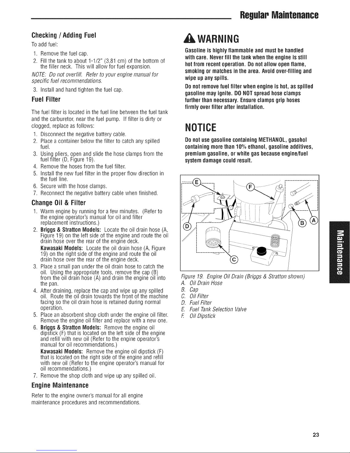
3. Using pliers, open and slide the hose clamps from the
fuel filter (D, Figure 19).
4. Removethe hosesfrom the fuel filter.
5. Install the new fuel filter in the proper flow direction in
the fuel line.
6. Securewith the hose clamps.
7. Reconnectthe negative battery cablewhen finished.
ChangeOil & Filter
1. Warm engine by running for a few minutes. (Referto
the engine operator's manualfor oil and filter
replacementinstructions.)
2. Briggs & Stratton Models: Locatethe oil drain hose (A,
Figure19) on the left side of the engine and route the oil
drain hose over the rear of the engine deck.
KawasakiModels: Locatethe oil drain hose (A, Figure
19) on the right side of the engine and route the oil
drain hose over the rear of the engine deck.
3. Placea small panunder the oil drain hoseto catch the
oil. Using the appropriate tools, remove the cap (B)
from the oil drain hose (A) and drain the engineoil into
the pan.
4. After draining, replacethe capand wipe up any spilled
oil. Route the oil drain towards the front of the machine
facing so the oil drain hose is retained during normal
operation.
5. Placean absorbent shop cloth under the engineoil filter.
Removethe engine oil niter and replacewith a new one.
6. 8riggs & Stratton Models: Removethe engineoil
dipstick (F) that is located on the left side of the engine
and refill with new oil (Refer to the engine operator's
manualfor oil recommendations.)
l(awasaki Models: Removethe engine oil dipstick (F)
that is locatedon the right sideof the engine and refill
with new oil (Refer to the engine operator's manual for
oil recommendations.)
7. Removethe shop cloth and wipe up anyspilled oil.
, WARNING
Gasolineis highlyflammable and mustbe handled
with care. Never fill thetankwhen the engine is still
hotfrom recentoperation. Donot allow open flame,
smokingor matchesin the area. Avoid over-filling and
wipe up any spills.
Donotremovefuel filter when engine is hot, as spilled
gasoline may ignite. DONOTspreadhoseclamps
further thannecessary.Ensureclampsgrip hoses
firmly over filter after installation.
NOTICE
Donot use gasoline containing METHANOL,gasohol
containingmorethan10% ethanol, gasoline additives,
premiumgasoline, or white gas becauseengine/fuel
systemdamage couldresult.
Figure 19. Engine OilDrain (Briggs & Stratton shown)
A. OilDrain Hose
B. Cap
C. Oil Filter
D. FuelFilter
E. Fuel TankSelection Valve
E OilDipstick
EngineMaintenance
Refer to the engine owner's manualfor all engine
maintenanceproceduresand recommendations.
23
Page 26

,ReguJapMaJflteflaflce
Lubrication
Lubricatethe unit at the locations shown in Figures 20
through 23 aswell asthe following lubrication points.
Grease:
• deck lift pivot blocks
i * front casterwheel axles & yokes
Use greasefittings when present. Disassembleparts to
apply greaseto moving parts when greasefittings are not
installed.
Not all greases are compatible. RedGrease(p/n 5022285)
is recommended,automotive-type high-temperature, lithium
greasemaybe usedwhen this is not available.
Oih
• mower deck spindles
• mower deck idler arm
* control handle pivots
* deck lift pivots
* seat plate pivots
* discharge chute hinge
Figure20. DeckLubrication
/
/
/,
// /
Generally,all moving metal partsshould be oiled where
contact is made with other parts. Keepoil and greaseoff
belts and pulleys. Rememberto wipe fittings and surfaces
cleanboth beforeand after lubrication.
Lubricatingthe FrontCasters:
NOTE.Front casters should be lubricated annually.
1. Removethe 1/4-28 bolt (A, Figure23) screwed into the
front caster and installa 1/4-28 greasefitting.
2. Greasethe front caster.
3. Removethe 1/4-28 greasefitting and reinstall the 1/4-28
bolt.
4. Repeatprocessfor the other side of the machine.
Figure21. ControlHandlePivots & Seat PlatePivots
Figure22. DeckLift Linkage Pivots
24 www.SnapperPro.com
\
Figure23. Front Caster& Wheel
A. 1/4-28Bolt
Page 27

Check/ Fiil TransmissionOil
Oil Type: 20W-50 conventional detergent motor oil.
1. Checkthe oil levelwhen the unit is cold. Locatethe
transmission oil reservoirs (A, Figure24) locatedon the
seatsupport plate. The oil should be up to the "FULL
COLD"mark (B). If the oil is below this level, proceed
to step 2.
2. Beforeremovingthe reservoir caps,makesure the area
around the reservoir capandfill neck of the reservoir is
free of dust, dirt, or other debris. Removethe reservoir
cap.
3. Add oil up to the "FULL COLD"mark (B).
4. Reinstallthe reservoir caps.
TransmissionOil Filter Change
Change Interval: Every 200 Hours
Replacement Filter Number: 5101026X1
1. Locatethe transmission oil filters (A, Figure25)
underneaththe rear of the machineon the
transmissions.
Figure24.
A.
B.
CheckingTransmissionOil Level
TransmissionOilReservoirs
"FULLCOLD"mark
RegularIVlaJntenance
2. Removethe three 1/4" filter guard screws (C) and the
filter guard (B).
3. Cleanthe areaaround thefilter baseand removethe
filter.
4. Apply afilm of new oil to the gasket of the new
replacementfilter. After the oil hasdrained,thread the
newfilter onto the filter base until the gasketmakes
contact,then tighten 3/4 of a turn more.
5. Reinstallthe filter guard with the three 1/4" filter guard
screws
6. Using a hex bit swivel socket or a modifiedallen wrench
removethe top port plug from the transmissions.
7. Removethe transmission reservoir cap and fiii with oil
until oil appearsatthe bottom of the transmission's top
port (approximately 2 qts (1,89L).
8. Reinstallthe top port plug and tighten to 15 ft Ibs (20,38
Nm).
9. Continueto add oil to the transmission oil reservoirs
until the oil levelreachesthe "FULL COLD"mark.
Reinstallthe oil reservoir cap.
10. Repeatthis processfor the other sideof the machine.
11. Runthe unit for several minutes and checkthe
transmission oil level.
Figure25. Transmission(Left Side Shown.)
A. TransmissionOil Filter
B. Filter Guard
C. 1/4" Filter Guard Screws
D. TopPort Plug
IMPORTANTNOTE:Usecaution after changing the filter, air
in thehydraulic system may affect the responsiveness of the
ground speed control levers. Repeatstep 11 until theair is
out of thesystem.
25
Page 28

RegWPMaintenance
Servicing The Mower Blades
Removing the MowerBlade
, CAUTION
Avoidinjury! Mower blades are sharp.
* Alwayswear gloves when handlingmower blades or
workingnear blades.
1. To removethe mower blade, use a 1" wrench on the
flats of the spindle shaft and remove the mower blade
mounting bolt with a 15/16" wrench (Figure26).
2. If there are no flats on the spindle shaft, wedgea
wooden block betweenthe mower blade andthe mower
deck housing to keepthe mower bladefrom turning.
inspectingthe MowerBlades
, DANGER
Avoid injury! A worn or damaged blade can break, and
a pieceof the mowerbladecouldbe throwninto the
operator's or bystander'sarea, resultingin serious
personalinjuryor death.
* Inspect the mowerblade every 25 hoursor at least
once a year.
* if the mower blade hits a solid object, stopthe
engine immediatelyand inspectthe mower blade.
. Never weld or straightenbentmower blades.
1. Removethe mower bladefrom the unit. SeeRemoving
the Blade.
2. inspect the mower blade (Figures 27 & 28). Discard the
mower blade if it has any of the below conditions.
A.) Has more than .5" (12,7 ram) of the mower blade
metal removed from previous sharpening or wear (D,
Figure27).
B.)The air lifts are excessivelyeroded (B & C, Figure
28) andthe notch (C) is .25" (6,35 mm) deepor greater.
C.) Mower blade is bent or broken.
3. If the cutting edgesarenot sharp or have nicks, sharpen
the blades. SeeSharpeningthe Mower Blades.
Figure26. Loosening theMower Blade for Removal
Figure27. Inspecting theMower Blade Tips
A. Mower BladeCutting Edge
B. SquareCorner
C. Air Lift
D. WearMeasurement - DISCARDMower BladeIf greater
than .5" (12,7 mm)
®
Figure28. inspecting the Mower BladeAir Lifts
A. New Mower Blade
B. Mower Bladeat WearLimit (A notch begins to form)
C. Mower Bladein DangerousCondition (Notch measures.25" (6,35 mm) or greater DONOTUSE.Replacewith new mower
blade.)
26 www.SnapperPro.com
Page 29

Sharpening the Mower 8Jade
ACAUTION
Avoidinjury! Mower blades are sharp.
• Alwayswear gloves whenhandlingthe mower
blades.
RegWPMaJflteflaflce
• Alwayswear safetyeye protectionwhen grinding.
1. Sharpenthe mower bladeswith grinder, handfile, or
electric bladesharpener.
2. Sharpenthe mower blade by removing an equal amount
of material from eachend of the mower blade.
3. Keepthe original bevel(A, Figure 29) when grinding. DO
NOTchangethe mower blade bevel.
4. The mower blade should have a maximum 1/64" (0,40
mm) cutting edge (B) or less.
5. Balancethe mower bladesbefore installing.
BaJancingthe MowerBJades
|CAUTION
Avoid injury! Keepmower bladesbalanced.
• An unbalancedmower blade cancreate excessive
vibrationand damage the unit or causemowerbJade
faiJnre.
1. Cleanthe mower bladeto removeany dried grass or
other debris.
2. SeeFigure30. Put the mower bladeon a nail in a vise
andturn the mower bladeto the horizontal position.
3. Checkthe balance of the mower blade. If either end of
the mower blademoves downward, sharpenthe heavy
end until the mower blade is balanced. SeeSharpening
the Mower Bladesfor proper sharpening instructions.
4. Repeatthe process until the mower blade remains in the
horizontal position.
®
Figure29. Sharpeningthe Mower Blade
A. Mower BladeBevel
B. Mower BladeCutting Edge
Figure30. Balancing the Mower Blade
A. Nail
Reinstalling the Mower Blades
1. Reinstalleachmower blade with the air lifts pointing up
towards the mower deckas shown in Figure31.
36" IVlodeis:Makesure the bladeis firmly seated in the
bladesaddle. Secure with the mower blademounting
bolt and flat washer (A & B, Figure31) and torque to 70
ft. ibs (94 Nm).
48" lVlodels:Securewith the mower blade mounting
bolt and flat washer (A & B, Figure31) and torque to 70
ft. Ibs (94 Nm).
2. If there are no fiats on the spindle shaft, wedgea
wooden block betweenthe mower blade andthe mower
deck housing to keepthe mower bladefrom turning.
\
\
Figure31. Tighteningthe Mower Blade for Installation
A. Mower Blade Mounting Bolt
B. Flat Washer
C. Mower BladeAir Lift (Points UpFor Installation)
D. 4 X 4 WoodenBlock
27
Page 30

RegWPMaJflteflaflce
GroundSpeed ControlLeverAdjustment
Thecontrol levers can be adjusted in three ways. The
alignment of the control levers, the placement of the levers
(how close the ends areto one another) and the height of
the levers can be adjusted.
ToAdjust the Handle Alignment
Loosenthe mount bolts (A, Figure32) and pivot the lever(s)
(B) to align with each other.
ToAdjust the Handle Placement
Loosenthe jam nuts and adjust the placementbolt (C,
Figure33) in or out to properly adjust the leverend spacing.
ToAdjust the Handle Height
Removethe mounting hardware and reposition the handle
either up or down from its original position. Youwill need
to readjust the handle alignment as described above.
SpeedBalancingAdjustment
If the rider veers to the right or left when the ground speed
control levers are inthe maximum forward position, the top
speedof eachof theselevers can be balancedby turning the
adjustment bolt(s) (A, Figure 33). 0nly adjust the speed of
the wheelthat is traveling faster.
ToReduce the Speedof the FasterWheel
1. Loosenthe securing nut.
2. Turn the top speed adjustment bolt COUNTER-
CLOCKWISEto reducethe speed.
3. Retightenthe securing nut when adjustment is
complete.
AWARNING
DO NOTadjust thetractorfor a faster overall speed
forward or reverse thanit was designed for.
Figure32. ControlLeverAdjustment
A. PlacementHardware
B. GroundSpeedControl Lever
Figure33. TopSpeedAdjustment
A. TopSpeedAdjustment Bolt
B. Control Lever Base
C. Alignment Hardware
Neutral Adjustment
if the tractor "creeps" while the ground speed control levers
are locked in their NEUTRALpositions, seeyour dealer.
28 www.SnapperPro.com
Page 31

ParkingBrakeAdjustment
1. Disengagethe PTO,stop the engine,engagethe parking
brake,and removethe key from the ignition.
2. Raisethe seat plate to gain accessto the parking brake
components.
3. Measurethe distancefrom the top of the brake spring
rod (C, Figure34) to the top of the lock nut (D) on both
sides of the unit. The measurementshould be .50"
(1,27 cm). If not, adjust the Iocknut to achievethe
measurementof .50" (1,27 cm)
4. Measurethe distance betweenthe bottom of the brake
shaftweldment (G) and the top of the set collar (F). The
measurementshould be .375" (0,95 cm). If not,
position the set collar until the measurementequals
.375" (0,95 cm).
if this dues not currectthe brakingprobJem,see yuur
Snapper Pru deaJer.
ReguiapMaJflteflaflce
Figure34.
A.
BrakeSpring
B.
First Measurement - .50" (1,27 cm)
C.
BrakeSpring Rod
D.
Lock Nut
E.
SecondMeasurement- .375" (0,95 cm)
F.
Set Collar
G.
BrakeShaft Weldment
ParkingBrakeAdjustment
29
Page 32

RegularMaintenance
Return-to-Neutral Adjustment
Todetermineif it is necessaryto adjust the neutral return,
perform the following steps.
1. Disengagethe PTO,engagethe parking brake and turn
off the engine.
2. Move the ground speedcontrol levers into the operating
position, pull the levers rearward and release.
3. Move the ground speedcontrol levers out towards the
neutral position. Ifthe leversdo not align with the
notches in the neutral lock plate, it is necessaryto
adjust the neutral return rod (B, Figure35).
Adjustment
WARNING
Toavoidseriousinjury, performadjustments only with
the engine stopped,the key removedand the tractoron
JeveJground.
1. Disengagethe PTO,engagethe parking brake and turn
off the engine.
2. There arethree jam nuts (A, Figure35) on the linkage
rod (B). The first two are usedtogetherto turn the rod
andthe third (towards the front of the machine) is used
to lock the rod in place. Loosenthe jam nut that locks
againstthe ball joint and turn the linkage rod to adjust.
If the machine creepsforward, turn the linkagerod
CLOCKWISE(while standing at the rear of the machine,
facing forward). If the machinecreeps backward,turn
the rod COUNTER-CLOCKWISE.
3. Lock the jam nut (A) against the balljoint when neutral
is achieved.
4. Pull the ground speedcontrol lever rearward and release
to check position again. Adjust as necessaryto align
the ground speedcontrol levers with the notches in the
neutral lock plate.
NOTE: This adjustment should not be performed while the
machine is running.
©
Figure35. Return-to-NeutralAdjustment
A. Jam Nuts
B. Neutral Return Rod
30 www.SnapperPro.com
Page 33
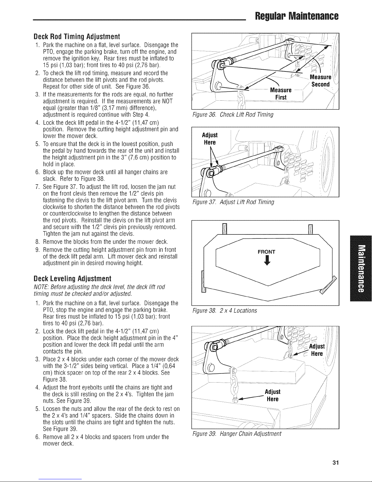
DeckRodTimingAdjustment
1. Parkthe machineon afiat, level surface. Disengagethe
PTO,engagethe parking brake,turn off the engine,and
removethe ignition key. Reartires must be inflated to
15 psi (1,03 bar); front tires to 40 psi (2,76 bar).
2. To check the lift rod timing, measure and record the
distancebetweenthe lift pivots and the rod pivots.
Repeatfor other sideof unit. SeeFigure 36.
3. If the measurements for the rods are equal, no further
adjustment is required. If the measurementsare NOT
equal (greaterthan 1/8" (3,17 mm) difference),
adjustment is required continue with Step4.
4. Lock the deck lift pedal in the 4-1/2" (11,47 cm)
position. Removethe cutting height adjustment pin and
lower the mower deck.
5. To ensure that the deck is in the lowest position, push
the pedalby hand towards the rear of the unit and install
the height adjustment pinin the 3" (7,6 cm) position to
hold in place.
6. Block up the mower deck until all hangerchains are
slack. Referto Figure38.
7. SeeFigure37. Toadjust the lift rod, loosen the jam nut
on the front clevisthen remove the 1/2" clevis pin
fastening the clevis to the lift pivot arm. Turnthe clevis
clockwiseto shorten the distance betweenthe rod pivots
or counterclockwise to lengthen the distance between
the rod pivots. Reinstallthe clevis on the lift pivot arm
and securewith the 1/2" clevis pin previously removed.
Tighten the jam nut against the clevis.
8. Removethe blocks from the underthe mower deck.
9. Removethe cutting height adjustment pin from in front
of the deck lift pedal arm. Lift mower deckand reinstall
adjustment pin in desired mowing height.
RegWPMaJflteflaflce
J
Figure36. CheckLift Rod Timing
Adjust /
Here
Figure37. Adjust Lift Rod Timing
/
DeckLevelingAdjustment
NOTE.Before adjusting the deck level, the deck lift rod
timing must be checked and/or adjusted.
1. Parkthe machineon afiat, level surface. Disengagethe
PTO,stop the engine and engagethe parking brake.
Reartires must be inflated to 15 psi (1,03 bar);front
tires to 40 psi (2,76 bar).
2. Lock the deck lift pedal in the 4-1/2" (11,47 cm)
position. Placethe deck height adjustment pin in the 4"
position and lower the deck lift pedaluntil the arm
contactsthe pin.
3. Place2 x 4 blocks under each corner of the mower deck
with the 3-1/2" sides beingvertical. Placea 1/4" (0,64
cm) thick spacer on top of the rear 2 x 4 blocks. See
Figure38.
4. Adjust the front eyeboits until the chains aretight and
the deck is still resting on the 2 x 4's. Tighten the jam
nuts. SeeFigure39.
5. Loosenthe nuts and allow the rear of the deck to rest on
the 2 x 4's and 1/4" spacers. Slide the chains down in
the slots until the chains are tight and tighten the nuts.
SeeFigure39.
6. Removeall 2 x 4 blocks and spacersfrom under the
mower deck.
Figure38. 2 x 4 Locations
Figure39. HangerChainAdjustment
31
Page 34
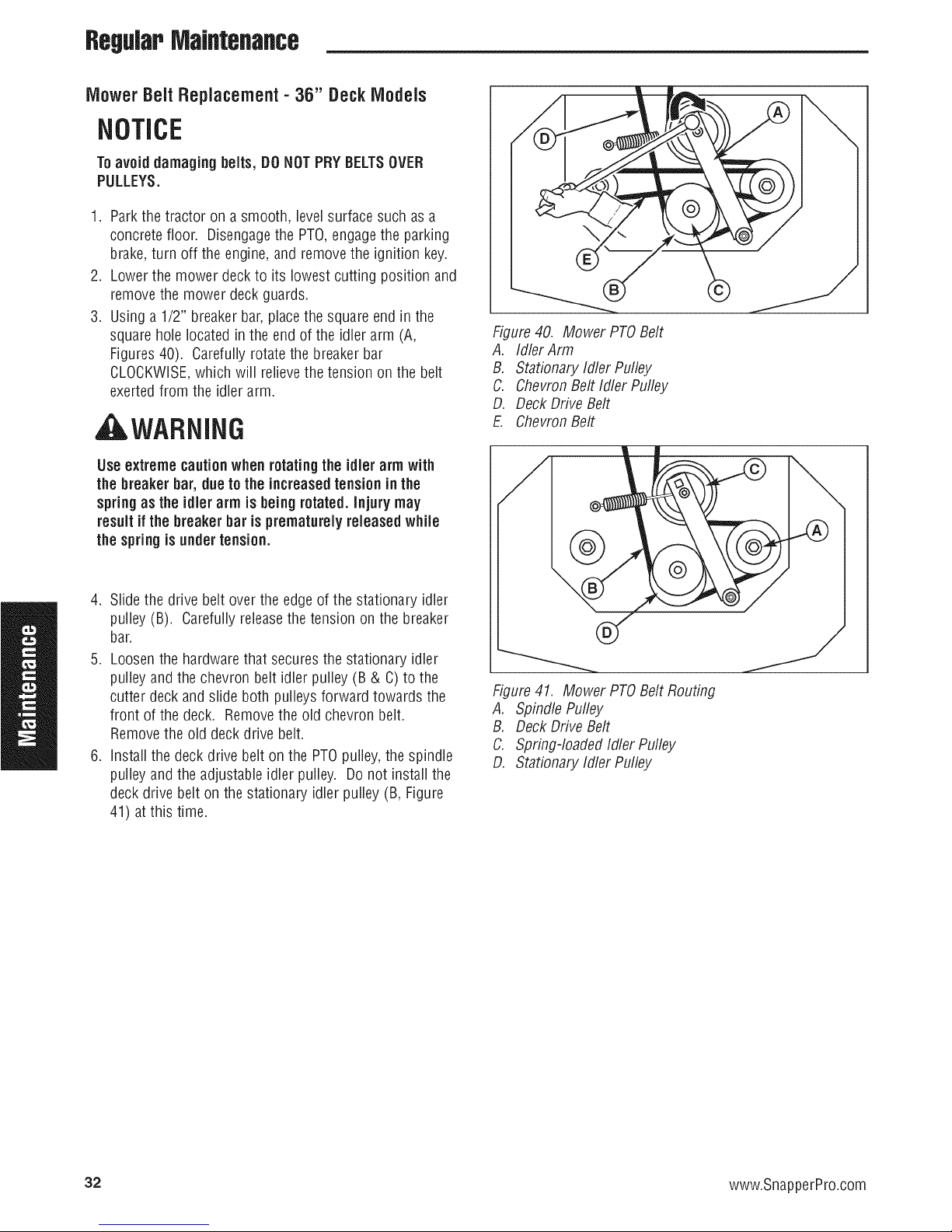
RegWPMaintenance
MowerBeltReplacement- 36" DeckIVlodeis
NOTICE
Toavoiddamaging belts, DONOTPRYBELTSOVER
PULLEYS.
1. Parkthe tractor on a smooth, levelsurface such as a
concretefloor. Disengagethe PTO,engagethe parking
brake,turn off the engine, and remove the ignition key.
2. Lowerthe mower deckto its lowest cutting position and
removethe mower deck guards.
3. Using a 1/2" breakerbar,placethe square end in the
squarehole located in the end of the idler arm (A,
Figures40). Carefullyrotatethe breaker bar
CLOCKWISE,which will relievethe tension on the belt
exertedfrom the idler arm.
AWARNING
Useextreme cautionwhen rotatingtheidler arm with
the breaker bar, dueto the increasedtensionin the
springas the idler arm is beingrotated.Injury may
resultif the breakerbar is prematurelyreleasedwhile
the springis undertension.
Figure40. Mower PTOBelt
A. Idler Arm
B. Stationary Idler Pulley
C. Chevron Belt Idler Pulley
D. Deck Drive Belt
E. ChevronBelt
4. Slidethe drive belt over the edge of the stationary idler
pulley (B). Carefullyreleasethe tension on the breaker
bar.
5. Loosenthe hardware that securesthe stationary idler
pulleyand the chevron belt idler pulley (B & C) to the
cutter deck and slide both pulleys forward towards the
front of the deck. Removethe old chevron belt.
Removethe old deck drive belt.
6. Install the deck drive belt on the PTOpulley,the spindle
pulleyand the adjustable idler pulley. Donot install the
deck drive belt on the stationary idler pulley (B, Figure
41) atthis time.
Figure41. Mower PTOBelt Routing
A. Spindle Pufley
B. Deck Drive Belt
C. Spring-loaded Idler Pulley
D. Stationary Idler Pulley
32 www.SnapperPro.com
Page 35
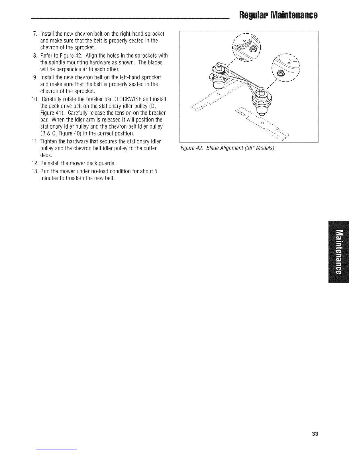
RegWPMaintenance
7. Install the new chevron belton the right-hand sprocket
and make surethat the belt is properly seated in the
chevron of the sprocket.
8. Referto Figure 42. Align the holes in the sprockets with
the spindle mounting hardwareas shown. The blades
will be perpendicularto eachother.
9. Install the new chevron belton the left-hand sprocket
and make surethat the belt is properly seated in the
chevron of the sprocket.
10. Carefully rotate the breaker bar CLOCKWISEand install
the deck drive belt onthe stationary idler pulley (D,
Figure41). Carefully releasethe tension on the breaker
bar. When the idler arm is releasedit will position the
stationary idler pulley and the chevron belt idler pulley
(B & C, Figure40) in the correct position.
11. Tighten the hardware that secures the stationary idler
pulleyand the chevron belt idler pulley to the cutter
deck.
12. Reinstallthe mower deck guards.
13. Runthe mower underno-load condition for about 5
minutes to break-inthe newbelt.
!
Figure42. BladeAlignment (36" Models)
33
Page 36
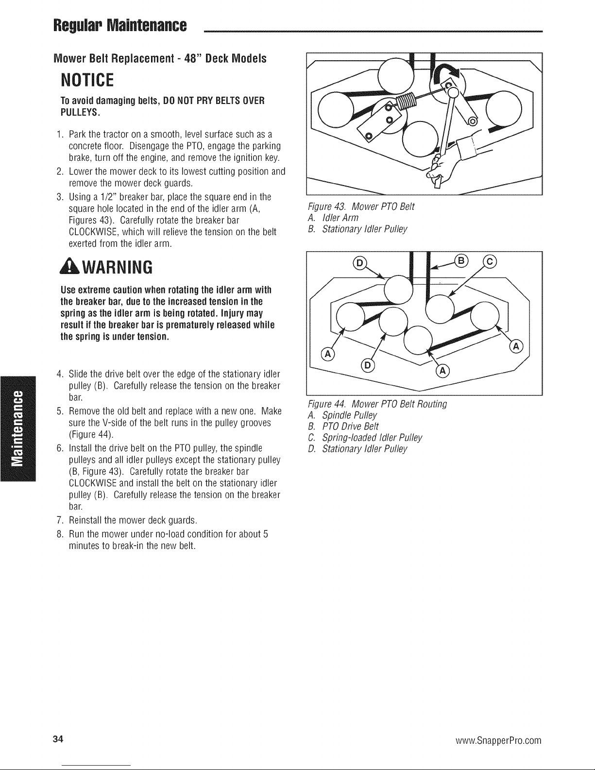
RegWPMaintenance
MowerBeltReplacement- 48" DeckIVlodeis
NOTICE
Toavoiddamaging belts, DOHOTPRY BELTSOVER
PULLEYS.
1. Parkthe tractor on a smooth, levelsurface such as a
concretefloor. Disengagethe PTO,engagethe parking
brake,turn off the engine, and remove the ignition key.
2. Lowerthe mower deckto its lowest cutting position and
removethe mower deck guards.
3. Using a 1/2" breakerbar,placethe square end in the
squarehole located in the end of the idler arm (A,
Figures43). Carefullyrotatethe breaker bar
CLOCKWISE,which will relievethe tension on the belt
exertedfrom the idler arm.
WARNING
Useextreme cautionwhen rotatingtheidler arm with
the breakerbar, duetothe increasedtensionin the
springas the idler arm is beingrotated.Injury may
resultif the breakerbar is prematurelyreleased while
the springis undertension.
\
Figure43. Mower PTOBelt
A. Idler Arm
B. Stationary Idler Pulley
/
4. Slidethe drive belt over the edge of the stationary idler
pulley (B). Carefullyreleasethe tension on the breaker
bar.
5. Removethe old belt and replacewith a newone. Make
surethe V-side of the belt runs in the pulley grooves
(Figure44).
6. Install the drive belt on the PTOpulley,the spindle
pulleys and all idler pulleys except the stationary pulley
(B, Figure43). Carefully rotate the breakerbar
CLOCKWISEand install the belt on the stationary idler
pulley (B). Carefullyreleasethe tension on the breaker
bar.
7. Reinstallthe mower deck guards.
8. Runthe mower under no-load condition for about 5
minutes to break-inthe new belt.
Figure44. Mower PTOBelt Routing
A. Spindle Pufley
B. PTODriveBelt
C. Spring-loaded Idler Pulley
D. Stationary Idler Pulley
34 www.SnapperPro.com
Page 37
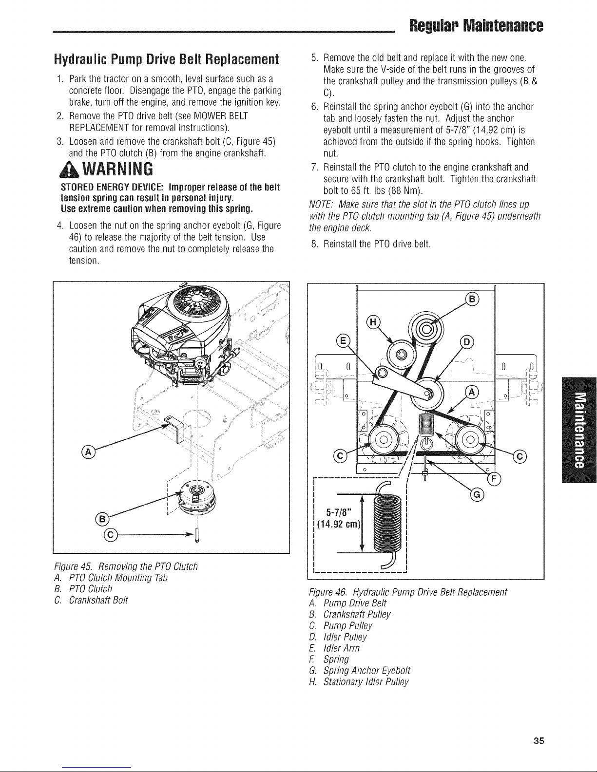
RegWPMaintenance
HydraulicPumpDriveBeltReplacement
1. Parkthe tractor on a smooth, levelsurface such as a
concretefloor. Disengagethe PTO,engagethe parking
brake,turn off the engine, and remove the ignition key.
2. Removethe PTOdrive belt (see MOWERBELT
REPLACEMENTfor removal instructions).
3. Loosenand removethe crankshaftbolt (C, Figure 45)
andthe PTOclutch (B) from the engine crankshaft.
AWARNING
STOREDENERGYDEVICE:improperrelease of the belt
tensionspringcanresultin personalinjury.
Useextreme cautionwhen removingthisspring.
,
Loosenthe nut on the spring anchor eyebolt(G, Figure
46) to releasethe majority of the belt tension. Use
caution and removethe nut to completely releasethe
tension.
5. Removethe old belt and replaceit with the new one.
Makesure the V-side of the belt runs in the grooves of
the crankshaftpulley and the transmission pulleys (B &
C).
6. Reinstallthe spring anchor eyeboit (G) into the anchor
tab and loosely fastenthe nut. Adjust the anchor
eyebolt until a measurementof 5-7/8" (14,92 cm) is
achievedfrom the outside if the spring hooks. Tighten
nut.
7. Reinstallthe PTOclutch to the enginecrankshaft and
secure with the crankshaft bolt. Tighten the crankshaft
bolt to 65 ft. Ibs (88 Nm).
NOTE. Makesure that the slot in the PTOclutch lines up
with the PTOclutch mounting tab (A, Figure 45) underneath
theenginedeck.
8. Reinstallthe PTOdrive belt.
©
Figure45. Removingthe PTOClutch
A. PTOClutch Mounting Tab
B. PTOClutch
C. CrankshaftBolt
I
Figure46. Hydraulic Pump Drive Belt Replacement
A. Pump DriveBelt
B. CrankshaftPulley
C. Pump Pulley
D. Idler Pulley
E. Idler Arm
F. Spring
G. Spring Anchor Eyebolt
H. Stationary Idler Pulley
35
Page 38
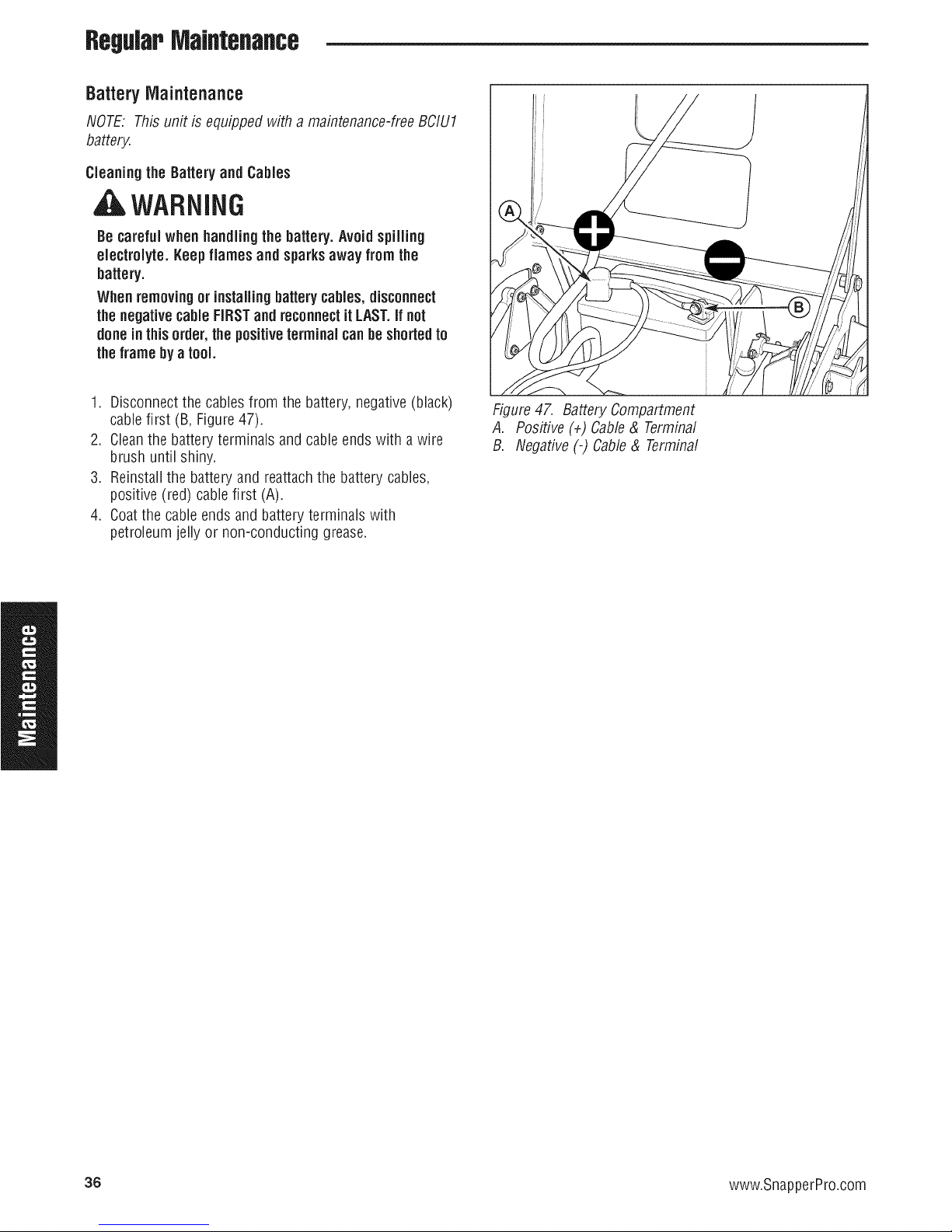
ReguJapMaJflteflaflce
BatteryMaintenance
NOTE: This unit isequipped with a maintenance-freeBCIU1
battery.
Cleaning the Battery and Cables
A WARNING
Be careful when handling the battery.Avoidspilling
electrolyte. Keepflames and sparksaway fromthe
battery.
Whenremovingor installingbatterycables,disconnect
thenegativecableFIRSTandreconnectit LAST.ifnot
donein thisorder, thepositiveterminalcanbeshortedto
theframeby a tool.
1. Disconnectthe cablesfrom the battery, negative(black)
cablefirst (B, Figure47).
2. Cleanthe battery terminals and cableendswith a wire
brush until shiny.
3. Reinstallthe battery and reattach the battery cables,
positive (red) cable first (A).
4. Coatthe cableends and battery terminals with
petroleum jelly or non-conducting grease.
Figure47. BatteryCompartment
A. Positive (+) Cable& Terminal
B. Negative(-) Cable& Terminal
36 www.SnapperPro.com
Page 39

RegWPMaintenance
BatteryService
Checking Battery Voltage
AWARNiNG
Keepopen flames and sparksawayfrom the battery;
the gassescomingfromit are highly explosive.
Ventilatethe batterywell duringcharging.
A voltmeter can be used to determine condition of battery.
Whenengine is off, the voltmeter shows battery voltage,
which should be 12 volts. When engine is running, the
voltmeter shows voltage of charging circuit which normally
is 13 to 14 volts.
A dead battery or one too weakto start the engine may not
meanthe battery needsto be replaced.Forexample, it may
meanthat the alternator is not charging the battery properly.
If there is anydoubt aboutthe causeof the problem, see
your dealer.If you needto replacethe battery,follow the
steps under Cleaningthe Battery & Cablesin the Regular
MaintenanceSection.
Charging a CompJeteJyDischargedBattery
1. Beawareof all the safety precautionsyou should
observeduring the charging operation. Ifyou are
unfamiliar with the use of a batterycharger and
hydrometer, havethe battery serviced byyour dealer.
2. Add distilled watersufficient to cover the plate (fill to the
proper level nearthe end of the charge). If the battery is
extremely cold, allow it to warm before adding water
becausethe water level will riseas it warms. Also, an
extremely cold battery will not accepta normal charge
until it becomeswarm.
3. Always unplug or turn the charger off before attaching
or removing the clamp connections.
4. Carefullyattachthe clamps to the battery in proper
polarity (usually red to [+] positive and black to [-]
negative).
5. While charging, periodically measurethe temperature of
the electrolyte, if the temperature exceeds125° F (51.6°
C), or if violent gassing or spewing of electrolyte occurs,
the charging rate must be reducedor temporarily halted
to prevent batterydamage.
6. Chargethe battery until fully charged(until the specific
gravity of the electrolyte is 1.250 or higher and the
electrolyte temperatureis at least 60° F).The best
method of making certain a battery is fully charged, but
not over charged, is to measurethe specific gravity of a
cell onceper hour. The battery is fully charged when the
cells are gassingfreely at low charging rateand less
than 0.003 changein specific gravity occurs over a three
hour period.
JumpStarting With AuxiJiary (Booster)Battery
Jump starting is not recommended. However,if it must be
done, follow these directions. Bothbooster and dis-charged
batteries should be treated carefully when using jumper
cables. Followthe steps below EXACTLY,beingcareful not to
cause sparks. Referto Figure48.
1. Both batteries must be of the samevoltage.
2. Position the vehicle with the booster battery adjacentto
the vehicle with the discharged battery so that booster
cables can be connectedeasilyto the batteries in both
vehicles. Makecertainvehicles do not touch each other.
3. Wear safety glassesand shield eyes andface from
batteriesat all times. Besure vent caps aretight. Place
damp cloth overvent caps on both batteries.
4. Connectpositive (+) cableto positive post of discharged
battery (wired to starter or solenoid).
5. Connectthe other end of same cableto same post
marked positive (+) on booster battery.
6. Connectthe second cablenegative (-) to other post of
booster battery.
7. Makefinal connection on engine block of stalled vehicle
away from battery. Do not leanover batteries.
8. Start the engine of the vehicle with the booster battery.
Wait a few minutes,then attempt to start the engine of
the vehicle with the discharged battery.
9. If the vehicle does not start after crankingfor thirty
seconds, STOPPROCEDURE.Morethan thirty seconds
seldom starts the engine unless some mechanical
adjustment is made.
10. After starting, allow the engineto returnto idle speed.
Removethe cable connection at the engineor frame.
Then remove the other end of the same cable from the
booster battery.
11. Removethe other cableby disconnecting at the
discharged battery first and then disconnect the
opposite end from the booster battery.
12. Discardthe damp cloths that were placedover the
batteryvent caps.
37
Page 40
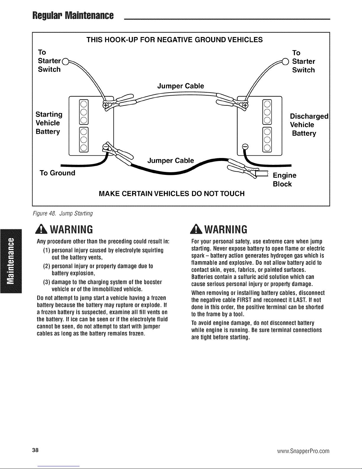
RegWPMaJflteflaflce
THIS HOOK-UP FOR NEGATIVE GROUND VEHICLES
To
Starter
Switch _ Jumper Cable
Starting l-_ '_l_
Vehicle
Battery
To Ground
MAKE CERTAIN VEHICLES DO NOT TOUCH
Figure48. Jump Starting
To
Starter
Switch
Discharged
Vehicle
_ Battery
Engine
Block
WARNING
Any procedureother thanthe precedingcouldresult in:
(1) personal injurycausedby electrolyte squirting
out the batteryvents,
(2) personal injuryor propertydamage due to
batteryexplosion,
(3) damage to the chargingsystem of thebooster
vehicleor of the immobilizedvehicle.
Do notattempt to jump start a vehicle havinga frozen
batterybecausethe batterymay ruptureor explode, if
a frozen batteryis suspected,examine all fill ventson
the battery,if icecanbe seen or ifthe electrolyte fluid
cannotbe seen, do notattempt to startwith jumper
cablesas long asthe batteryremainsfrozen.
,A WARNING
Foryour personalsafety,use extreme carewhen jump
starting.Neverexpose batterytoopen flame or electric
spark- batteryaction generates hydrogengas which is
flammable and explosive. Donot allow batteryacid to
contactskin, eyes, fabrics, or painted surfaces.
Batteriescontaina sulfuricacid solutionwhich can
causeseriouspersonalinjury or property damage.
When removingor installingbatterycables, disconnect
the negativecable FIRSTand reconnectit LAST.if not
done in thisorder, the positiveterminal canbe shorted
totheframe by atool.
Toavoid engine damage, do notdisconnect battery
while engine is running.Be soreterminal connections
are tight before starting.
38 www.SnapperPro.com
Page 41

RegularIVlaJflteflaflce
Storage
TemporaryStorage (30 DaysOr Less)
Remember,the fuel tank will still contain some gasoline, so
neverstore the unit indoors or in anyother area where fuel
vapor could travel to any ignition source. Fuelvapor is also
toxic if inhaled,so never store the unit in any structure used
for human or animal habitation.
Hereis a checklist of things to do when storing your unit
temporarily or in between uses:
* Keepthe unit in an areaawayfrom where children may
come into contact with it. if there's any chanceof
unauthorized use, removethe spark plug (s) and put in a
safe place. Besure the spark plug opening is protected
from foreign objectswith a suitable cover.
* if the unit can't be stored on areasonablelevelsurface,
chockthe wheels.
* Cleanall grass and dirt from the mower.
LongTerm Storage (Longer Than 30 Bays)
Beforeyou store your unit for the off-season, readthe
MaintenanceandStorageinstructions in the SafetyRules
section, then perform the following steps:
1. Draincrankcaseoil while engine is hot and refill with a
grade of oil that will be requiredwhen unit is used again.
2. Preparethe mower deckfor storage asfollows:
a. Removemowerdeckfrom the unit.
b. Cleanundersideofmowerdeck.
c. Coatall baremetalsurfaceswith paint or lightcoat of
oil to preventrusting.
3. Cleanexternal surfaces and engine.
4. Prepareenginefor storage. Seeengine owner's
manual.
5. Cleanany dirt or grass from cylinder headcooling fins,
engine housing and air cleaner element.
6. Coverair cleanerandexhaustoutlet tightly with plastic
or other waterproof material to keepout moisture, dirt
and insects.
7. Completelygreaseand oil unit as outlined in the Normal
Caresection.
8. Cleanup unit and apply paint or rust preventativeto any
areaswhere paint is chippedor damaged.
9. Besure the battery is filled to the proper level with water
and is fully charged. Battery life will be increasedif it is
removed,put in a cool, dry placeandfully charged
about oncea month. If battery is left in unit, disconnect
the negativecable.
WARNING
Never storethe unit, with gasoline in engine or fueJ
tank, in a heatedshelteror in enclosed, poorly
ventilatedenclosures. Gasoline fumes may reach an
open flame, sparkor pilot light (such as a furnace,
water heater,clothesdryer, etc.) and causean
expJosion.
Handlegasoline carefully, it is highly flammable and
carelessuse couldresult in serious fire damage to
yourpersonor property.
Drainfuel into an approved containeroutdoors away
from open flame or sparks.
10. Drainfuel system completely or add a gasolinestabilizer
to the fuel system. If you have chosen to usea fuel
stabilizer and have not drained the fuel system, follow all
safety instructions and storage precautions in this
manualto prevent the possibility of fire from the ignition
of gasolinefumes. Remember,gasolinefumes cantravel
to distant sourcesof ignition and ignite, causing risk of
explosion and fire.
NOTE:Gasoline,if permitted to stand unused for extended
periods (30 daysor more), may developgummy deposits
which can adverselyaffect theenginecarburetor and cause
enginemalfunction. Toavoid this condition, add a gasoline
stabilizer to the fuel tank andrun theengine a few minutes,
or drain aft fuel from the unit before placing it in storage.
Starting After Long Terra Storage
Beforestarting the unit after it has beenstored for a long
period of time, perform the following steps.
1. Removeany blocks from under the unit.
2. install the battery if it was removed.
3. Unplugthe exhaustoutlet and air cleaner.
4. Fillthe fuel tank with fresh gasoline.Seeengine
manualfor recommendations.
5. See engine owner's manualand follow all instructions
for preparing engine after storage.
6. Checkcrankcaseoil level and add proper oil if
necessary.If any condensationhas developedduring
storage, drain crankcaseoil and refill.
7. inflate tires to proper pressure. Checkfluid levels.
8. Start the engine and let it run slowly. DONOTrun at
high speed immediately after starting. Be sure to run
engine only outdoors or in well ventilated area.
39
Page 42

TeoubleshootJflg
Troubleshooting
TroubleshootingChart
AWARNING
While normal care and regularmaintenancewill extend the
life of your equipment, prolonged or constant use may
eventually requirethat service be performed to allow it to
continue operating properly.
Thetroubleshooting guide below lists the most common
problems, their causesand remedies.
Seethe information on the following pagesfor instructions
Toavoidseriousinjury, performmaintenance on the
tractor or moweronly whenthe engine is stoppedand
the parkingbrakeengaged.
Always removethe ignition key, disconnect thespark
plugwire and fasten it away from the plug before
beginningthe maintenance,to preventaccidental
startingof the engine.
on how to perform most of these minor adjustments and
service repairsyourself. If you prefer, all of these
procedures can be performed for you by your local
authorized dealer.
Troubleshootingthe Rider
Problem
Enginewill notturnover or start.
Enginestartshardor runs poorly. 1. Fuelmixture too rich. 1. Cleanair filter. Checkchokeadjustment.
Engineknocks. 1. Low oil level. 1. Check!add oil as required.
Excessiveoil consumption. 1. Engine running too hot. 1. Cleanengine fins, blower screen and
Engineexhaust is black. 1. Dirty air filter. 1. Replaceair filter. See engine manual.
Cause
1. Parking brake not engaged.
2. PTO(electric clutch) switch
in ON position.
3. Ground speed control levers
not in "NEUTRAL" position.
4. Out of fuel.
5.
Engineflooded.
6.
Fuseblown.
7.
Batteryterminals require
cleaning.
Battery discharged or dead.
8. 8. Rechargeor replace.
Wiring loose or broken.
9. 9. Visually check wiring & replacebroken or
10. Solenoid or starter motor faulty. 10. Repair or replace. Seeauthorized dealer
11. Safety interlock switch 11. Replaceas needed.Seeauthorized
faulty, service dealer.
12. Spark plug(s)faulty, fouled 12. Cleanand gap or replace.
or incorrectly gapped. See engine manual.
13. Water in fuel. 13. Drain fuel & replacewith fresh fuel.
14. Gasis old or stale. 14. Drain fuel & replace with fresh fuel.
2. Spark plug faulty,fouled, or 2. Cleanand gapor replace.
incorrectly gapped. (Seeengine manual.)
2. Using wrong gradeoil. 2. Seeengine manual.
2. Using wrong weight oil. 2. See engine manual.
3. Too much oil in crankcase. 3. Drain excessoil.
2. Enginechoke control 2. Openchoke control.
is inclosed position.
Remedy
1. Engageparking brake.
2. Placein OFFposition.
3. Moveground speed control leversto
"NEUTRAL" position.
4. if engine is hot, allow it to cool, then refill
the fuel tank.
5. Movechoke control to closed position.
6. Replacefuse.
7. Cleanthe batteryterminals
frayed wires. Tighten loose connections.
air cleaner.
40 www.SnapperPro.com
Page 43

Rider Troub/eshooting Continued.
Problem
Engineruns,butriderwill
notdrive.
Rider drive belt slips. 1. Pulleys or belt greasy or oily• 1
Brakewill not hold. 1. Brake is incorrectlyadjusted• 1
Ridersteersor handlespoorly. 1. Steering linkage is loose• 1
Cause
1. Transmission releaselever(s)
in "open" position•
2. Belt is broken• 2.
3. Drive belt slips• 3.
4. Brake is not fully released• 4.
2. Tensiontoo loose• 2.
3. Belt stretched or worn• 3.
2. Brake pads worn• 2.
2. Improper tire inflation• 2.
Troubleshootingthe Mower
Problem Cause
Mower will not raise. 1. Lift linkagenot properly attached
or damaged•
Engine stalls easily with 1. Enginespeedtoo slow. 1.
mower engaged. 2. Ground speedtoo fast. 2.
3. Cutting height settoo low. 3.
4. Discharge chute jamming 4.
with cut grass•
Excessive mower vibration.
Excessive belt wear or breakage. 1. Bentor rough pulleys. 1.
Mower drive beJtsJips 1. Idler pulley spring broken or not 1.
or fails to drive, properly attached.
Mower does not engage. 1. Electricalwiring damage. 1.
1. Blademounting bolts are loose• 1.
2. Mower blades,arbors, 2.
or pulleys are bent.
3. Mower blades are out 3.
of balance•
4. Belt installed incorrectly. 4.
2. Using incorrect belt. 2.
2. Mower drive belt broken• 2.
2. PTOclutch not adjusted 2.
3. Batteryvoltage too low. 3.
TPoubleshootiflg
Remedy
1. Movethetransmissionreleaselever(s)to
the"closed"position•
See Drive Belt Replacement.
See problem and causebelow•
Seeauthorized service dealer
•Cleanas required•
Adjust spring tension•
See Drive Belt Replacement
Replacebelt.
•See Brake Adjustment•
Replacewith new brake pads•
•Check and tighten any looseconnections•
See Regular MaintenanceSection•
Remedy
1.Seeauthorizedservicedealerfor repair.
Set to full throttle•
DecreaseGround Speed•
Cuttall grass at maximum cutting
height during first pass.
Cut grasswith discharge pointing toward
previously cut area.
Tighten to 70 ft.lbs. (94 N.m.).
Checkand replaceas necessary•
Remove,sharpen, and balanceblades•
See MaintenanceSection•
ReinstallCorrectly•
Repairor replace•
Replacewith correct belt.
Repairor replaceas needed•
Replacedrive belt.
Locate& repair damagedwire.
See PTOClutch Adjustment section
Rechargebattery and check alternator•
See Battery Maintenance section•
41
Page 44

TroubleshootJflg
TroubleshootingCommonCutting
Problem
Streaking.
Scalping.
Problems
Cause
1. Bladesare not sharp.
2. Bladesare worn down to far.
3. Enginespeed istoo slow.
4. Ground speed istoo fast.
5. Deckis pluggedwith grass
6. Not overlapping cutting rows
enough.
7. Not overlapping enough when
turning.
1. Lawn is uneven or bumpy.
2. Mower deck cutting height is
settoo low.
3. Ground speed istoo fast.
4. Deckis not leveledcorrectly.
5. Tire pressure is low or uneven
SteppedCutting. 1. Deck is not leveledcorrectly.
2. Tires are not properly inflated.
3. Bladesare damaged.
4. Deckshell isdamaged.
5. Mower spindle is bent or loose.
6. Bladesare installed incorrectly.
Remedy
1.Sharpenyourblades.
2. Replaceyour blades.
3. Always mow at full throttle.
4. Slow down.
5. Cleanout the mower.
6. Overlapyour cutting rows.
7. When turning your effective cutting width
decreases-overlap more when turning.
1. Roll or level the lawn.
2. Raisethe cutting height.
3. Slow down.
4. Correctly level the deck.
5. Checkand inflatethe tires.
1. Levelthe deck correctly.
2. Checkand inflatethe tires.
3. Replacethe blades.
4. Repairor replacethe deck.
5. Repairor replacethe spindle.
6. Reinstallthe bladescorrectly.
Uneven Cutting.
Stingers.
1. Deck is not leveledcorrectly.
2. Bladesare dull or worn.
3. Bladesare damaged.
4. Deckis clogged with grass
clippings.
5. Deckshell is damaged.
6. Mower spindle is bent or loose.
7. Bladesare installed incorrectly.
8. Tires are not properly inflated.
1. Bladesare not sharp or nicked.
2. Bladesare worn down too far.
3. Enginespeed is too slow.
4. Ground speed istoo fast.
5. Deckis pluggedwith grass.
1. Levelthe deck correctly.
2. Sharpenor replace the blades.
3. Replacethe blades.
4. Cleanout the deck.
5. Repairor replacethe deck.
6. Repairor replacethe spindle.
7. Reinstallthe bladescorrectly.
8. Checkand inflatethe tires.
1. Sharpenyour blades.
2. Replaceyour blades.
3. Always mow at full throttle.
4. Slow down.
5. Cleanout the mower.
42 www.SnapperPro.corn
Page 45

Specifications
SpecificsUofls
NOTE.Specificationsare correct at time of printing and aresubject to changewithout notice.
ENGINE:
19 HPKawasaki
Make
Model
Horsepower
Displacement
ElectricalSystem
OilCapacity
Kawasaki
FH580V
19 @3600 rpm
35.7 Cu. in (585 cc)
12 Volt Starter, 13 amp. Alternator,
Battery: 340 CCA
1.9 US qt. ( 1.8 L) w/Filter
26 liP Briggs& Stratton
Make
Model
Horsepower
Displacement
ElectricalSystem
Oil Capacity
Briggs & Stratton
44P777-O124-G1
26 @3600 rpm
44.2 Cu. in (724 cc)
12 Volt Starter, 16 amp. Alternator,
Battery: 340 CCA
2.0 US qt.. (1.9 L) w/Filter
CHASSIS:
FnelTank
RearWheels
Front Wheels
Capacity: 8 Gallons (30,3 L)
Tire Size: 20 x 7.00 -10 (36" Model)
Tire Size: 20 x 8.00 -10 (48" Model)
Inflation Pressure: 15 psi (I ,03 bar)
Tire Size: 11 x 4.00 - 5
Inflation Pressure: 40 psi (2,76 bar)
TRANSMISSIONS:
idydroGearZL-KMEF-3LTC-1LLX(Lid)
idydroGearZL-GMEF-3L7B-1LL×(Rid)
Type
HydraulicFlnid
Speeds
@3400rpm
ContinuousTorque
Ontpnt
MaximnmWeight
onAxle
DIMENSIONS:
Overall Length: 68" (173 cm)
OverallWidth
36"Model: 37"(94 cm)
48"Model: 49"(125 cm)
Height: 43" (109 cm)
Weight (apx.): 750Ibs.(340 kg)
ZT2800
SAE20W-50 motor oil
Forward: 0-7 MPH (0-11,27 km/h)
Reverse:0-5 MPH (0-8.05 km/h)
180 ft. Ibs. (244 N.m.)
440 Ibs. (200 Kg) per axle
EnginePowerRating Information
Thegross power rating for individual gas engine models is labeledin accordancewith SAE(Society of Automotive Engineers)
codeJ1940 (Small Engine Power & Torque Rating Procedure), and rating performance has been obtainedandcorrected in
accordancewith SAEJ1995 (Revision 2002-05). Torquevaluesare derivedat 3060 RPIVl;horsepowervalues are derivedat
3600 RPM. Actual gross engine powerwill be lower and is affected by, among other things, ambient operating conditions and
engine-to-enginevariability. Givenboth the wide array of products on which enginesare placedand the variety of
environmental issues applicableto operating the equipment, the gas enginewill not develop the rated gross power when used
in a given pieceof power equipment (actual"on-site"or net horsepower). This difference is due to a variety of factors
including, but not limited to, accessories (air cleaner,exhaust,charging, cooling, carburetor,fuel pump, etc.), application
limitations, ambient operating conditions (temperature, humidity, altitude), and engine-to-engine variability. Dueto
manufacturing and capacity limitations, Briggs & Stratton may substitute an engine of higher rated powerfor this Series
engine.
43
Page 46

LLJ
-J
t_
113
F-
In
0
t_
113
rr
t_
0
rr
Q.
t_
0
Z
0
..3
,<
t_
.3
0
!1.
@
LLJ
Q
0
7"
0
m
0
n
LL
u
F-.
Z
LLJ
Q
Z
LLJ
Q.
0
.3
44 www.SnapperPro.com
:iov-_n$ 7VOll_:IA v Hli_ _90_ SIH1 NgI7V
Page 47

Ferris Industries - a division of Simplicity Manufacturing Inc.
Owner's Limited Warranty Information
(Effective 04/28/2004)
Thank you for purchasing Ferris commercial mowing equipment. Please take a few minutes to read this limited warranty information. It contains all
the information you will need to have your Ferris mower repaired in the unlikely event that a breakdown covered by this limited warranty should occur.
Owner's Responsibilities - As a condition to our obligations under this limited warranty, you shall have read the operator's manual and you shall have
completed and submitted to Ferris, within 20 days from the date of purchase, the Ferris Product Registration. You must properly service and maintain
your Ferris product as described in the operator's manual. Such routine maintenance, whether performed by a dealer or by you, is at your expense.
The Ferris equipment, including any defective part covered by this limited warranty, must be returned to an authorized Ferris dealer within the warranty
period for warranty service. This limited warranty extends only to equipment operated under normal conditions and in accordance with Ferris' instruc-
tions.
Warranty Start Date - The limited warranty coverage begins on the day you buy your new Ferris commercial mowing equipment. An authorized Ferris
dealer will assist you in filling out a Ferris Product Registration with specific information for the model you purchase and your personal information,
which must be returned to Ferris.
Limited Warranty - The limited warranty, set forth below, is a written guarantee by Ferris, during the warranty period, to repair or replace parts which
have a substantial defect in materials or workmanship. The warranty is "limited" because it is for a specified period of time, applies to the original pur-
chaser only, and is subject to other restrictions.
FERRIS LIMITEDWARRANTY
Ferris Industries (Ferris) warrants, in accordance with the provisions below, to the original purchaser only, for the periods described below that the
commercial mower shall be free from substantial defects in material or workmanship under normal use and service. If you wish to file a claim under
this limited warranty, you must provide prompt notice of your claim to an authorized Ferris dealer during the warranty period. Ferris' obligation under
this limited warranty is, at Ferris' option, to repair or replace any part or parts of the mower, which, in the judgment of Ferris, are found to be defective
and covered by this limited warranty. An authorized Ferris dealer will repair or replace the defective part or parts, at the dealer's place of business, at
no charge for the labor or parts. This limited warranty applies only to mowers sold in the United States and Canada and is subject to the following limi-
tations.
Covered Parts
All Mowers
*Belts, Tires, Brake Pads
And Hoses, Battery, Blades
*Attachments
*Engine
Items and Conditions Not Covered
This warranty does not cover, and Ferris makes NO WARRANTY regarding, the following:
• Mowers or their parts if a complete and accurate Ferris Product Registration has not been received by Ferris.
• Loss or damage to person or property other than that expressly covered by the terms of this limited warranty.
• Pickup and delivery charges and risk of loss or damage in transit to and from any authorized Ferris dealer.
• Any damage or deterioration due to normal use, wear and tear, or environmental or natural elements, or exposure.
• Cost of regular maintenance service or parts, such as but not limited to, filters, fuel, lubricants, tune-up parts, and adjustments.
• Claims arising due to failure to follow Ferris' written instructions, or improper storage or maintenance.
• Any repairs necessary due to use of parts, accessories or supplies, including gasoline, oil or lubricants, incompatible with the mowing equipment,
or other than as recommended in the operator's manual or other written operational instructions provided by Ferris.
• Use of non-Ferris approved parts or accessories.
• Any overtime or other extraordinary repair charges or charges relating to repairs or replacements.
• Rental of like or similar replacement equipment during the period of any warranty, repair or replacement work.
• Loss of revenue, time or use of the mowing equipment.
• Travel, telephone or other communication charges.
• Damage from continued use of defective mowing equipment.
• Freight charges on replacement parts.
• Any mowing equipment or part which, in the judgment of Ferris, has been altered or tampered with in any way or has been subjected to misuse,
abuse, abnormal usage, unauthorized repair, neglect or accident, damage in transit, or has had the serial numbers altered, effaced or removed.
• Any equipment, part or item not mentioned under "Covered Parts," above.
General Conditions
Ferris is continually striving to improve its products, and therefore reserves the right to make improvements or changes without incurring any obligation
to make changes or additions to products sold previously. Any oral or written description of Ferris products is for the sole purpose of identifying the
products and shall not be construed as an express warranty. No warranty claim shall give rise to a right for the purchaser to cancel or rescind any
sale. No person is authorized to make any warranty or assume for Ferris any liability not strictly in accordance with this limited warranty. Any assis-
tance Ferris provides to or procures for the purchaser outside the terms, limitations or exclusions of this limited warranty will not constitute a waiver of
the terms, limitations or exclusions of this limited warranty, nor will such assistance extend or revive the limited warranty. Ferris will not reimburse the
purchaser for any expenses incurred by the purchaser in repairing, correcting or replacing any defective products except for those incurred with Ferris'
prior written permission and in accordance with this limited warranty.
Ferris' sole and exclusive liability with respect to this limited warranty, and the purchaser's exclusive remedy, shall be repair or replacement as set forth
herein. All warranty work must be performed by an authorized Ferris dealer using only Ferris approved replacement parts. FERRIS SHALL HAVE NO
LIABILITY FOR ANY OTHER COST, LOSS OR DAMAGE, INCLUDING BUT NOT LIMITED TO, ANY INCIDENTAL, COMPENSATORY, INDIRECT,
PUNITIVE, SPECIAL OR CONSEQUENTIAL LOSS OR DAMAGE. FERRIS' AGGREGATE LIABILITY WITH RESPECT TO A DEFECTIVE PROD-
UCT OR PART SHALL BE LIMITED TO AN AMOUNT EQUAL TO THE MONIES PAID BY THE PURCHASER FOR THAT DEFECTIVE PRODUCT
OR PART. THIS LIMITED WARRANTY, AND FERRIS' OBLIGATIONS HEREUNDER, ARE EXCLUSIVE AND IN LIEU OF ALL OTHER WAR-
RANTIES, EXPRESS OR IMPLIED, INCLUDING, WITHOUT LIMITATION, THE IMPLIED WARRANTY OF MERCHANTABILITY AND THE IMPLIED
WARRANTY OF FITNESS FOR A PARTICULAR PURPOSE. FERRIS SHALL NOT BE LIABLE TO THE PURCHASER, OR TO ANYONE CLAIMING
UNDER THE PURCHASER, FOR ANY OTHER OBLIGATIONS OR LIABILITIES, INCLUDING, BUT NOT LIMITED TO, OBLIGATIONS OR LIABILI-
TIES ARISING OUT OF BREACH OF CONTRACT OR WARRANTY, NEGLIGENCE OR OTHER TORT OR ANY THEORY OF STRICT LIABILITY,
WITH RESPECT TO FERRIS PRODUCTS OR FERRIS' ACTS OR OMISSIONS OR OTHERWISE.
It is the express wish of the parties that this agreement and any related documents be drafted in English. II est la volonte expresse des parties que
cette convention et tousles documents s'y rattachent soient rediges en anglais.
Warranty Period
2-years (24 months) from date of retail purchase by the original
purchaser for parts & labor (90 days for rental mowers)
(Except as noted below*)
90 days from date of retail purchase by the original purchaser
1 year from date of retail purchase by the original purchaser
If the engine manufacturer provides any warranty on the mower's engine, Ferris will assign that warranty to the
original purchaser of the mower if such assignment is reasonably practicable. Please refer to the engine man-
ufacturer's warranty statement, if any, that is included in the owner's packet. We are not authorized to handle
warranty adjustments or repairs on engines. Ferris offers NO WARRANTY on mower engines. Ferris does not
guarantee or represent that any engine manufacturer will comply with the terms of its warranty.
Page 48
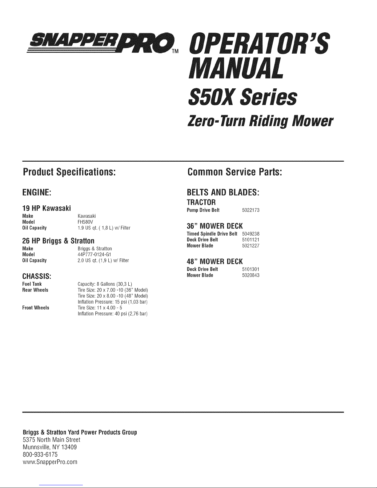
MANUAL
Series
Zero-TurnRiding
'S
ProductSpecifications:
ENGINE:
19 HPKawasaki
Make Kawasaki
Model FH580V
Oil Capacity 1.9 US qt. ( 1,8 L) w/Filter
26 HP Briggs & Stratton
Make Briggs & Stratton
Model 44P777-O124-G1
Oil Capacity 2.0 US qt. (1,9 L) w/Filter
CHASSIS:
Fuel Tank
Rear Wheels
Front Wheels
Capacity: 8 Gallons (30,3 L)
Tire Size: 20 x 7.00 -10 (36" Model)
Tire Size: 20 x 8.00 -10 (48" Model)
Inflation Pressure: 15 psi (I ,03 bar)
Tire Size: 11 x 4.00 - 5
Inflation Pressure: 40 psi (2,76 bar)
CommonService Parts:
BELTSAND BLADES:
TRACTOR
Pump Drive Belt 5022173
36" MOWER DECK
Timed Spindle Drive Belt 5049238
Deck Drive Belt 5101121
Mower Blade 5021227
48" MOWER DECK
DeckDrive Belt 5101301
Mower Blade 5020843
Briggs & Stratton Yard PowerProductsGroup
5375 North Main Street
Munnsville, NY 13409
800-933-6175
www.SnapperPro.com
 Loading...