

Page 1

ASSEMBLY INSTRUCTIONS
OPERATOR'S MANUAL
PARTS LIST
Z
-VAC
Large Clamshell
Grass Catcher
Kit for NZM
Actual product may differ from product pictured above
Manual No. 7100651 (I.R. 4/5/2006)
TP 900-5178-IR-AT-N
Mid Mount
Riders
Models covered:
Includes Clamshell, Blower
and Weight Kits
48” Kit P/N 7600026
52” Kit P/N 7600027
61” Kit P/N 7600028
Page 2

1
preliminaries
Congratulations!
You have just purchased one of the finest pieces of outdoor power equipment on the market today. If properly cared for,
your new Z-Vac Grass Catcher Kit will provide years of dependable service. Please read and follow this instruction manual carefully in order to get the most out of your new equipment.
As you carefully unpack your unit, you will find the following items:
1 Blower Kit (48” P/N 3071107, 52” P/N 3071108, 61” P/N 3063348)
1 Large Clamshell Catcher Kit (All, 7600019)
1 Weight Kit (All, 7600025)
1 Package containing operating manuals and warranty registration
Each product leaves our factory in excellent condition; occasionally, however, some damage may occur during shipment.
If any such damage is found upon initial inspection, immediately notify the transport carrier who delivered your machine,
as they are solely responsible for such damage, as well as any subsequent adjustments necessary.
Before assembly, please take a moment and record your model number and serial number below for future reference (both
numbers are located on the serial tag attached to the blower):
Model number_______________________________
Serial number________________________________
Also be sure to promptly fill out and return the warranty registration enclosed in your manual packet.
Your new unit requires very little assembly. Simply follow the instructions contained within this manual to begin enjoying
the benefits of your new unit.
2
Page 3

safety rules regarding outdoor power equipment
IMPORTANT! READ CAREFULLY THE FOLLOWING SAFETY RULES BEFORE
ASSEMBLING OR OPERATING UNIT.
2
TRAINING
-- Read, understand, and follow all instructions in the man-
ual and on the unit before starting. If the operator(s) or
mechanic(s) can not read English it is the owner's responsibility to explain this material to them.
-- Become familiar with the safe operation of the equipment,
operator controls, and safety signs.
-- All operators and mechanics should be trained. The
owner is responsible for training the users.
-- Only allow responsible adults, who are familiar with the
instructions, to operate the unit.
-- Never let children or untrained people operate or service
the equipment. Local regulations may restrict the age of the
operator.
-- The owner/user can prevent and is responsible for accidents or injuries occurring to themselves, other people or
property.
PREPARATION
-- Evaluate the terrain to determine what accessories and
attachments are needed to properly and safely perform the
job. Use only accessories and attachments approved by
the manufacturer.
-- Wear appropriate clothing including safety shoes, safety
glasses and ear protection. Long hair, loose clothing or jewelry may get tangled in moving parts.
-- Inspect the area where the equipment is to be used and
remove all objects such as rocks, toys and wire, which can
be thrown by the machine.
-- Use extra care when handling gasoline and other fuels.
They are flammable and vapors are explosive.
a) Use only an approved container.
b) Never remove fuel cap or add fuel with the engine running. Allow engine to cool before refueling. Do not smoke.
c) Never refuel or drain the machine indoors.
-- Check that operator's presence controls, safety switches
and shields are attached and functioning properly. Do not
operate unless they are functioning properly.
OPERATION
-- Never run an engine in an enclosed area.
-- Operate only in the daylight or with good artificial light,
keeping away from holes and hidden hazards.
-- Be sure of your footing while using pedestrian controlled
equipment, especially when backing up. Walk, don't run.
-- Do not operate in reverse unless absolutely necessary.
Always look down and behind before and while traveling in
reverse.
-- Be aware of the blower discharge direction and do not
point it at anyone. Do not operate the blower without hose
and bagger hood in place.
-- Never leave a running unit unattended. Always stop
engine before leaving unit.
-- Never operate with guards not securely in place. Be sure
all safety features are attached, adjusted properly and functioning properly.
-- Never operate with the hose or cover removed or altered.
-- Do not change the engine governor setting or over speed
the engine.
-- Stop on level ground, shut off engine before leaving the
operator's position for any reason.
-- Stop equipment and inspect impeller blades after striking
objects or abnormal vibration occurs. Make necessary
repairs before resuming operations.
-- Keep hands and feet away intake and discharge areas.
-- Keep pets and bystanders away.
-- Do not operate the unit while under the influence of alco-
hol or drugs.
-- Use caution when crossing roads and sidewalks. Stop
engine if not blowing.
-- Use care when loading or unloading the machine into a
trailer or truck.
-- Use care when approaching blind corners, shrubs, trees
or other objects that may obscure vision.
SLOPE OPERATION
Slopes are a major factor related to loss-of-control and tipover accidents, which can result in severe injury or death.
All slopes require extra caution. If you cannot back up the
slope, or if you feel uneasy on it, do not drive on it.
Do
-- Mow up and down slopes, never across face.
-- Remove obstacles such as rocks, tree limbs, etc.
-- Watch for holes, ruts, or bumps. Uneven terrain could
overturn the unit. Tall grass can hide obstacles.
-- Keep all movement on the slopes slow and gradual. Do
not make sudden changes in speed or direction.
Do Not
-- Do not start or stop on a slope. If tires lose traction, pro-
ceed slowly straight down the slope.
-- Do not turn on slopes unless necessary, and then, turn
slowly and gradually downhill, if possible.
-- Do not use near drop-offs, ditches, or embankments. The
operator could lose footing or balance or blower could suddenly turn over if a wheel is over the edge of a cliff or ditch,
or if an edge caves in.
-- Do not operate on slopes with wet grass. Reduced footing or traction could cause sliding.
-- Do not operate machine on slopes in excess of 10
degrees (18% grade) when equipped with a grass catcher.
-- Do not operate machine without weight kit installed when
equipped with a grass catcher.
3
Page 4

2
safety rules regarding outdoor power equipment
CHILDREN
Tragic accidents can occur if the operator is not alert to the
presence of children. Children are often attracted to the unit
and its activity. Never assume that children will remain
where you last saw them.
-- Keep children out of the mowing area and under the
watchful care of another responsible adult.
-- Do not allow children or others to ride on the machine,
attachment, or towed equipment (even with the blades off).
-- Be alert and turn unit off if children enter the area.
-- Before and during reverse operation, look behind and
down for small children.
-- Never allow children to operate the unit.
-- Use extra care when approaching blind corners, shrubs,
trees, or other objects that may obscure vision.
EMISSIONS
-- Engine exhaust from this product contains chemicals
known, in certain quantities, to cause cancer, birth defects,
or other reproductive harm.
-- Look for the relevant Emissions Durability Period and Air
Index information on the engine emissions label.
MAINTENANCE AND STORAGE
-- Always observe safe refueling and fuel handling practices
when refueling the unit after transportation or storage.
-- Always follow the engine manual instructions for storage
preparations before storing the unit for both short and long
term periods.
-- Always follow the engine manual instructions for proper
start-up procedures when returning the unit to service.
-- Never store the machine or fuel container inside where
there is an open flame, such as in a water heater. Allow unit
to cool before storing.
-- Shut off fuel while storing or transporting. Do not store fuel
near flames or drain indoors.
-- Keep all hardware tight and keep all parts in good working condition. Replace all worn or damaged decals.
-- Never tamper with safety devices. Check their proper
operation regularly.
-- Clean leaves and debris from mufflers and engine to prevent fires. Clean up oil or fuel spillage.
-- Stop and inspect the equipment if you strike an object.
Repair, if necessary, before restarting.
-- Never make adjustments or repairs with the engine running unless specified otherwise.
-- Park machine on level ground. Never allow untrained personnel to service machine.
-- Carefully release pressure from components with stored
energy. (e.g. springs)
-- Only replace impellers. Never straighten or weld them.
-- Keep hands and feet away from moving parts.
-- Frequently check components and replace with manufac-
turer's recommended parts, when necessary.
-- Use only factory authorized replacement parts when making repairs.
-- Always comply with factory specifications on all settings
and adjustments.
-- Only authorized service locations should be utilized for
major service and repair requirements.
-- Never attempt to make major repairs on this unit unless
you have been properly trained. Improper service procedures can result in hazardous operation, equipment damage and voiding of manufacturer's warranty.
4
Page 5
unit assembly
3
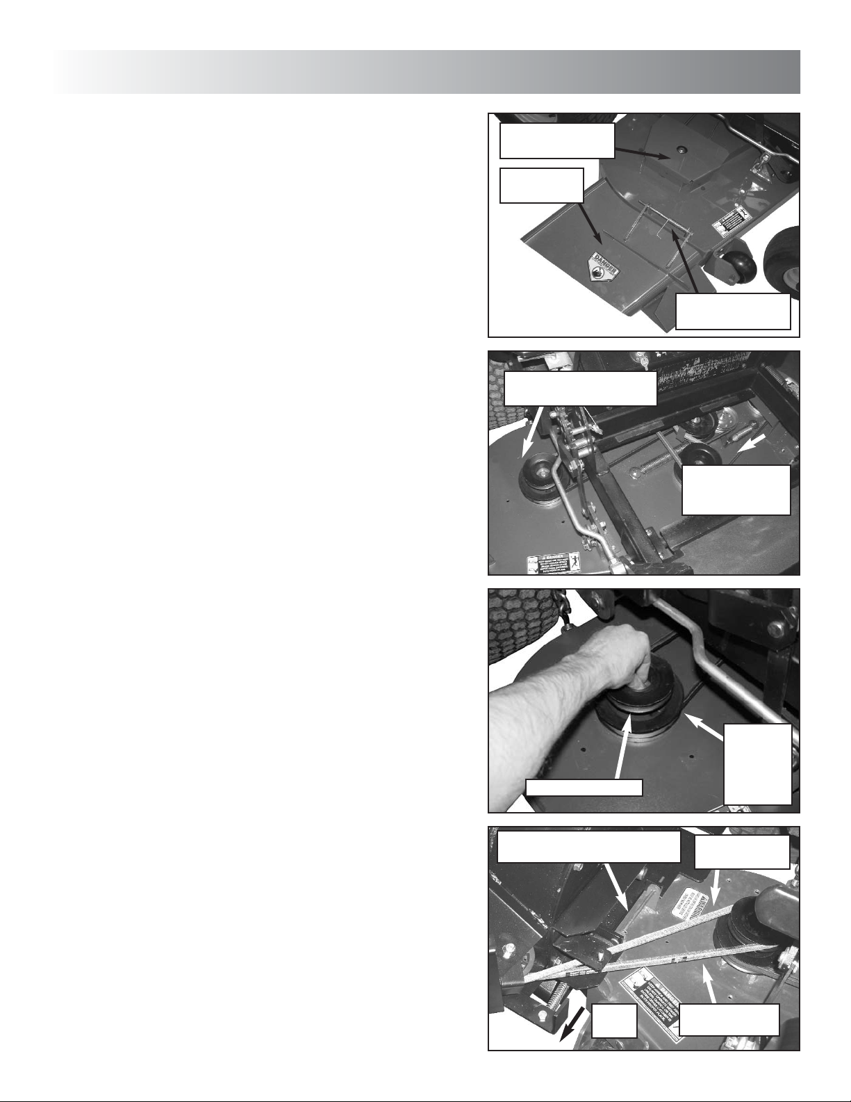
BLOWER KIT INSTALLATION
STEP 1: Remove pin, rod and spring securing dis-
charge deflector to mower deck, and remove
deflector. Set rod and pin aside for future assembly step. Store deflector for future use. IMPOR-
TANT: Never operate mower without discharge
deflector or grass catcher securely in place.
STEP 2: Remove two bolts securing right deck pulley guard to mower deck and remove guard. Set
bolts aside for future assembly step. Store guard
for future use. IMPORTANT: Never operate mower
without a pulley guard securely in place.
STEP 3: Lift off and set aside foot rest/center deck
cover to expose senter blade deck. Pull blade belt
deck idler arm in direction indicated to relieve belt
tension, and slip blade belt off of right blade drive
pulley.
NOTE: Assistance may be needed for removal of
blade belt.
REMOVE PULLEY
GUARD
REMOVE
DEFLECTOR
REMOVE PIN,
ROD AND SPRING
REMOVE BELT FROM
RIGHT BLADE PULLEY
PULL ON IDLER
TO RELIEVE
BELT TENSION
STEP 4: Remove nut securing pulley to blade
spindle, and install supplied blower pulley on top of
existing pulley. Replace nut, and torque to 70-80 ftlbs. Replace deck belt onto groove of bottom pulley.
NOTE: Nut secures blade bolt in place. Support
bolt from beneath while installing pulley.
IMPORTANT: Use gloves when working under
deck. Sharp blades can cause injury.
STEP 5: Set blower against deck discharge. Align
holes in blower mount with holes in deck discharge
tabs, and secure blower with discharge deflector
rod removed in Step 1, securing with pin. NOTE:
Do not reinstall the deflector spring when installing
the rod.
STEP 6: Pull back on idler tension release handle,
and install blower belt around top groove of deck
pulley. NOTE: Make sure belt is not rolled or
twisted when installing.
BLOWER PULLEY
INSTALL BLOWER AND
SECURE WITH ROD AND PIN
PULL
BACK
REPLACE
BELT
ONTO
BOTTOM
PULLEY
FROM UPPER
IDLER PULLEY
TO LOWER
IDLER PULLEY
5
Page 6
3
unit assembly
REMOVE BOLTS,
THEN REMOVE
COVER
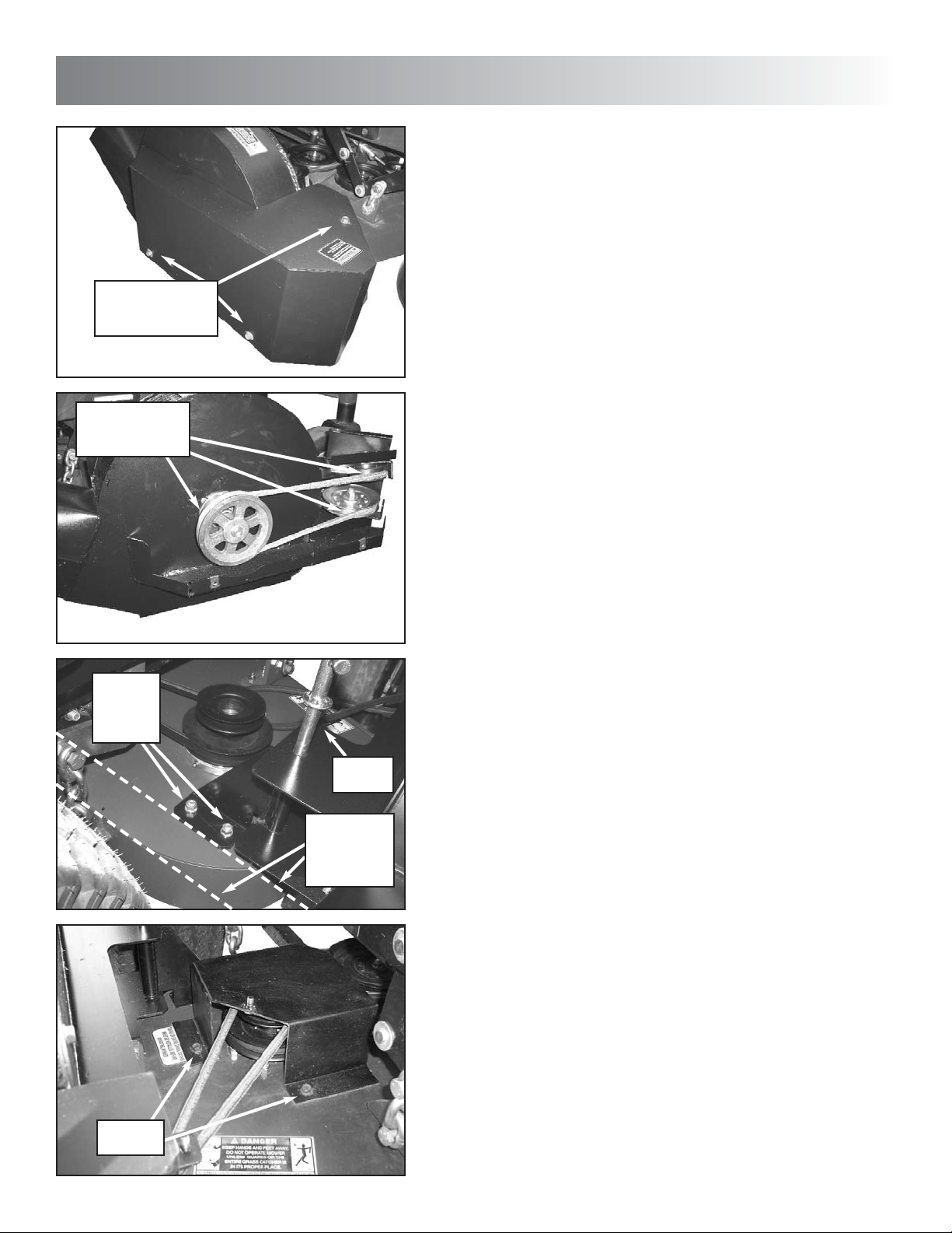
STEP 6a: Remove bolts securing impeller pulley
cover to blower, and remove cover.
CHECK TO SEE
THAT BELT IS
ON PULLEYS
DRILL
HOLES &
INSTALL
BOLTS
INSERT
PIN
ALIGN
BRACKET
WITH REAR
OF DECK
STEP 6b: Check to see that blower belt is routed
around impeller pulley and idler pulleys after belt is
installed onto deck pulley. Replace cover, tightening bolts securely. IMPORTANT: Never operate
any mower without a pulley guard securely in
place.
STEP 7: Slip tube of locking pin bracket into blower mount, and secure with T-handle pin, making
sure pin goes through both upper and lower holes
in blower mount. Then align base of pin bracket
parallel with rear of deck, and, using bracket as a
template, drill two 7/16” holes through deck. Insert
two 3/8-16 x 1” hex bolts up through deck and
bracket, securing with hex flange lock nuts.
Tighten securely. IMPORTANT: Use gloves when
working under deck. Sharp blades can cause
injury.
INSTALL
BOLTS
STEP 8: Lay supplied pulley guard onto deck,
aligning holes in guard with holes in deck. Install
with bolts securing original guard, tightening
securely.
NOTE: 48” deck shown; 52” and 61” deck guard
configurations may differ.
6
Page 7
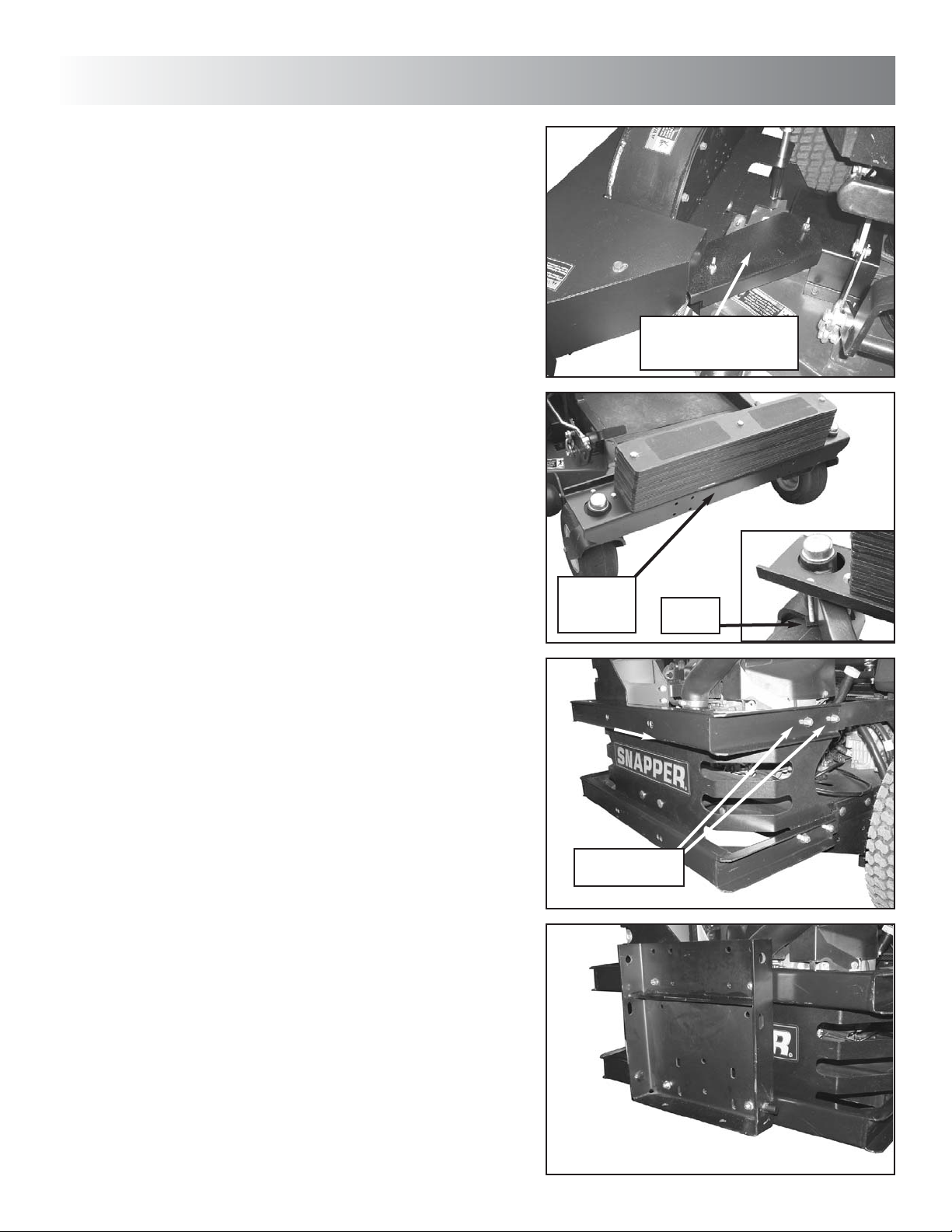
STEP 9: Install belt guard between pulley guard
and belt guard support clip on front part of blower
mount. Secure with two 5/16 nylon wing nuts.
Tighten nuts securely.
WEIGHT KIT INSTALLATION
!! Warning: Weight kit must be installed prior to
installing clamshell kit. Failure to do so may
result in longitudal tipping of unit.
!! Warning: Assistance is required when
installing weight kit.
unit assembly
INSTALL BELT GUARD
AND SECURE WITH
WING NUTS
3
STEP 10: Lay weight mount channel, with installed
weights, across front end of machine as shown.
Secure to machine with two clamp plates, one
under each caster arm, each held on with two 3/816 x 4” hex bolts and lock nuts. See Inset. Tighten
securely.
CLAMSHELL KIT INSTALLATION
STEP 11: Install bumper mount standoffs onto rear
bumper of machine, utilizing existing hardware on
machine. NOTE: Invert hardware when installing
standoffs, installing bolts out through bumper with
nuts facing out.
NOTE: When installing standoffs, be sure that the
bumper mount plate mounting holes along the
back bar of both standoffs are oriented towards the
right side of the machine. Refer to the Parts List
section of the manual.
STEP 12: Install bumper mount plate onto standoffs with four 5/16-18 x 3/4 hex bolts, securing with
four 5/16-18 hex flange lock nuts. Tighten securely.
WEIGHT
MOUNT
CHANNEL
USE EXISTING
HARDWARE
CLAMP
PLATE
7
Page 8
3
unit assembly
RAISE UNIT
HOOK CLAMSHELL
MOUNT ONTO
BUMPER MOUNT
PLATE PINS
SECURE
WITH
HAIR PIN
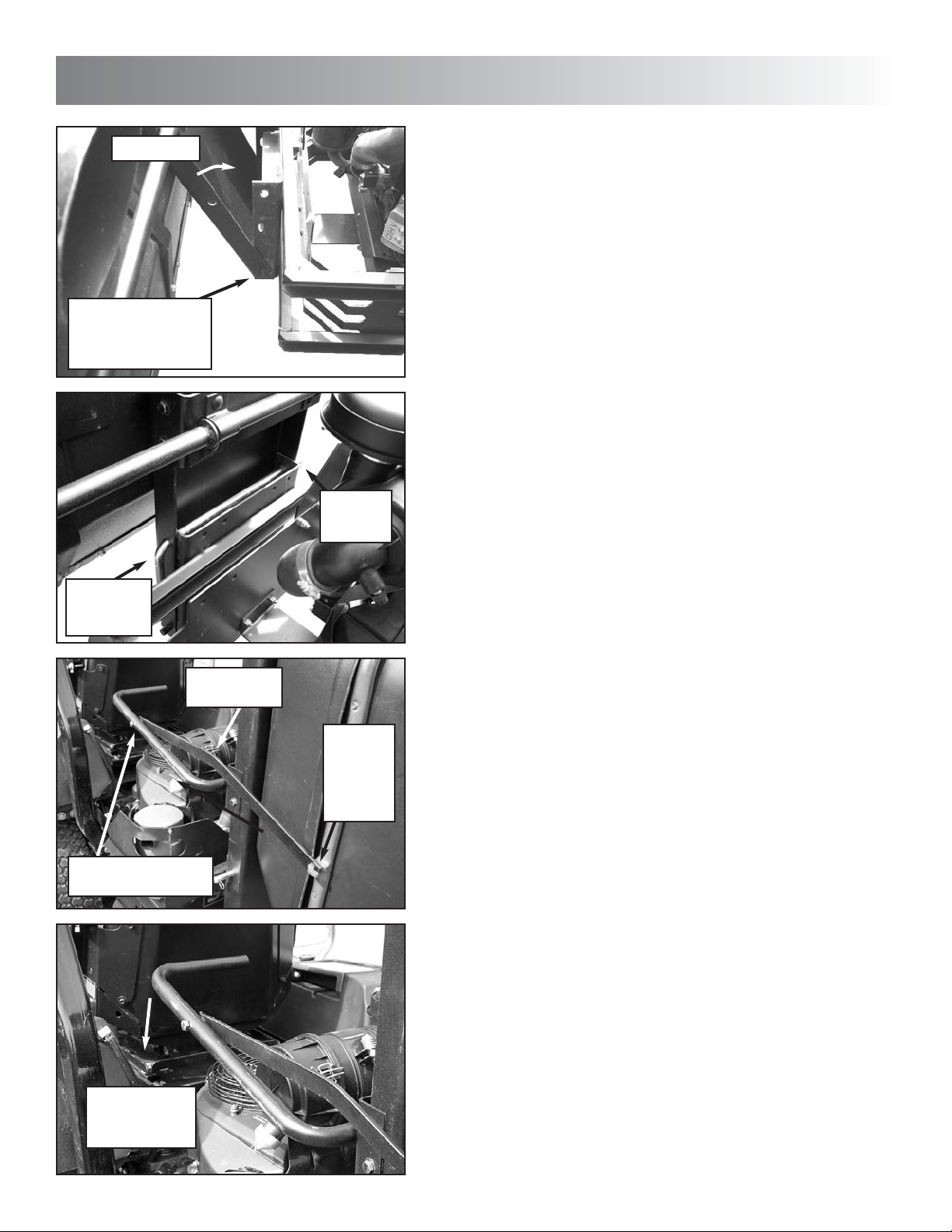
STEP 13: Hook bottom of clamshell mount onto
pins in bottom of bumper mount plate, then raise
clamshell assembly up against bumper mount.
IMPORTANT: Assistance is required when
installing clamshell unit.
STEP 14: Slide hitch rod through aligned holes in
clamshell mount and bumper mount plate, securing with hair pin.
IMPORTANT: Assistance is required when
installing clamshell unit.
SLIDE ROD
THROUGH
HOLES
BOLT ARM TO
INSIDE OF HANDLE
MAKE SURE
BEND IS UP
HOOK
LARGE
HOLE OF
ARM
HERE
STEP 15: Hook the large hole of each actuating
arm onto the hook on each side of the rear cover.
Then secure the other end of the arm onto the
inside of each side of the handle weldment with
one 3/8-16 x 2” hex bolt and nyloc nut. Tighten
snugly. NOTE: Make sure bend of arm is up.
Push handle down to lock cover.
PUSH HANDLE
DOWN TO
LOCK COVER
8
Page 9
unit assembly
3
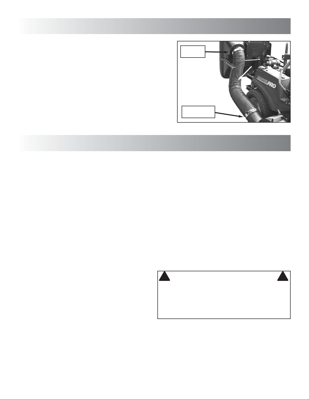
STEP 16: Slip one hose clamp onto each side of
discharge hose, and install hose between blower
and clamshell. NOTE: Install hose so that clamp
with nut is on the clamshell side, and the clamp
with the black quick-release knob is on the blower
side. Tighten both clamps securely.
INTRODUCTION
Follow operation and maintenance instructions in the
Operator’s Manual provided with the Snapper MidMount Z-Rider.
GRASS CATCHER OPERATION
1. Select desired cutting height. Choose a setting that will
not attempt to cut off too much at once, overloading the
machine.
2. After starting engine and allowing a brief warm up period, move engine speed control to highest setting.
3. Drive machine to cutting area. Engage blades.
4. Select a slow forward ground speed until familiar with
conditions. Do not select a speed that is too fast, causing the machine to become overloaded.
5. The weight of the grass catcher and contents will affect
the stability and handling of the machine. Avoid sudden
starts and sharp turns. Reduce speed on slopes, and
DO NOT operate machine on slopes exceeding 10
degrees (18% grade). Operate machine up and down
slopes. DO NOT operate machine across the face of
slopes. Turn blades off when traveling up slope.
6. Empty grass catcher often to minimize effect on stability and handling. Over filling the catcher will reduce performance and cause clogging of the hose, blower and
deck.
7. Do not operate the machine with the Grass Catcher
open. The entire Grass Catcher must be installed, the
catcher closed and latched properly before operating.
EMPTYING GRASS CATCHER
1. Empty Grass Catcher often to avoid overfilling.
Overfilling reduces performance and causes clogging of
hose, blower and deck.
2. Turn blades off. Drive machine to location the clippings
are to be dumped. DO NOT operate blades in reverse.
CLAMP
WITH NUT
CLAMP WITH
BLACK KNOB
unit operation & maintenance
If you must back machine to dump clippings in desired
location, LOOK and SEE behind and down for children,
pets and hazards before and while backing.
3. Stop motion of machine by returning Motion Control(s)
to Neutral (N). Set Park Brake. Stop engine.
4. Lift up on handle sufficiently to allow all clippings to exit
catcher. If the dumped pile is too high to allow the catcher to close, you may be required to use a rake or similar implement to distribute the clippings.
5. After dumping, to maintain peak performance, check
the catcher screen located on the inside of the Rear
Cover Assembly to make sure it is clean and free of any
build up. Clean as required with brush or broom.
6. Close catcher. Push down firmly on handle to insure it
is properly latched.
7. Re-start engine and drive machine to cutting area. Set
engine speed to highest setting, engage blades and
resume operation.
! !
DO NOT attempt to remove any clogs from deck, blower, or hose with engine or blade running. STOP engine.
STOP blades. Set brake. Remove key. Make sure
blades and all rotating components have come to a
complete stop before removing any catcher or unclogging any catcher component.
IF THE GRASS CATCHER BECOMES CLOGGED
The grass catcher may become plugged if the conditions
are too severe, the catcher is overfilled, or the machine is
used improperly. If plugging does occur, attempt the following:
1. Engine speed too slow – set engine speed control to
“FAST” position.
WARNING
(Continued On Next Page)
4
9
Page 10

4
unit operation & maintenance
IF THE GRASS CATCHER BECOMES CLOGGED
(Continued From Previous Page)
2. Empty catcher more often.
3. Clean screen on rear cover assembly.
4. Ground speed too fast – cut at slower speed.
5. Removing too much grass – raise cutting height, cut
partial width, and cut lawn more frequently.
6. Grass is too wet from rain or dew – allow grass to dry.
7. Blades are dull or worn – inspect blades and replace as
necessary. Use only genuine SNAPPER replacement
blades.
8. Deck, blower, or hose has clipping build up – clean all
clippings from all internal surfaces.
! !
DO NOT put fingers or hands inside blower! STOP
blades. STOP engine. Remove key. Use only a stick, or
other suitable means, to clear the blower of clogs or
other obstructions!
! !
DO NOT attempt any adjustments, maintenance or
repairs with engine running. STOP blades. STOP
engine. Remove key.
! !
Grass Catcher components are subject to deterioration. Inspect frequently. Replace worn or damaged
components immediately. Use only genuine SNAPPER
replacement parts.
To Clear A Plugged Hose
1. Stop blades. Stop engine. Remove key.
2. After all rotating components (engine, blower, blades)
have come to a complete stop, loosen hose clamp at
outlet of blower, and remove hose from blower.
3. Clear any obstructions from hose. If necessary, use a
stick to reach into the hose.
4. Reinstall hose to blower and securely tighten hose
clamp.
WARNING
WARNING
WARNING
To Clear A Plugged Blower
1. Stop blades and blower. Stop engine. Remove key.
2. After all rotating components have come to a complete
stop, loosen the hose clamp at the outlet of the blower.
3. Remove hose from blower.
4. Using a stick or similar object, clear all obstructions
from blower. DO NOT INSERT HAND.
5. Reinstall hose to blower and securely tighten hose
clamp.
GRASS CATCHER MAINTENANCE
Grass Catcher components are subject to wear and deterioration during normal usage. Inspect all components frequently for signs of wear and deterioration. Replace worn or
damaged components immediately.
BEFORE EACH USE
1. Perform pre-start checklist and maintenance as
instructed in the SNAPPER Mid-Mount Z-Rider
Operator’s Manual and Engine Owner’s Manual included with the machine.
2. Clamshell Catcher. Inspect all catcher components.
Replace all worn or damaged parts.
3. Deck, Blower, Hose. Clean grass build up from deck,
blower, hose, covers and rear cover screen. To maintain
peak performance make sure screen is clean at each
dumping.
4. Hose. Check hose for wear, tears and holes. Replace
as needed.
5. Blades. Check blades for sharpness, wear, flatness
and damage. Refer to MMZ Operator’s Manual for
blade wear limits and sharpening/replacement instructions.
6. Blower. Check blower impeller, blower housing and
inlet/outlets for signs of wear and deterioration. Replace
as needed. Check all fasteners and hardware to insure
none are missing and all are tightened securely.
Lubricate impeller shaft bearings with 1 to 3 shots of
General Purpose grease from a grease gun.
7. Belts. Check belts for wear and fraying. Replace as
needed.
8. Idler Arm. Check idler arm to insure it pivots freely and
bushings are not worn. Replace worn bushings as
needed.
10
Page 11

warranty statement
5
2 YEAR LIMITED WARRANTY
For two (2) years from purchase date for the original purchaser's residential, non-commercial use, SNAPPER, through any
authorized SNAPPER dealer will replace, free of charge (except for taxes where applicable), any part or parts found upon
examination by the factory at McDonough, Georgia, to be defective in material or workmanship or both.
For one (1) year from purchase date for the original purchaser's commercial, non-residential use, SNAPPER, through any
authorized SNAPPER dealer will replace, free of charge, any part or parts found upon examination by the factory at
McDonough, Georgia, to be defective in material or workmanship or both.
For ninety (90) days from purchase date for the original purchaser's rental use, SNAPPER, through any authorized SNAPPER dealer will replace, free of charge, any part or parts found upon examination by the factory at McDonough, Georgia,
to be defective in material or workmanship or both
All transportation costs incurred by the purchaser in submitting material to an authorized SNAPPER dealer for replacement under this warranty must be paid by the purchaser.
This warranty does not apply to certain transmissions, to engines and their components, and batteries, as these items are
warranted separately. This warranty does not apply to parts that have been damaged by accident, alteration, abuse,
improper lubrication, normal wear, or other cause beyond the control of SNAPPER. This warranty does not cover any
machine or component part that has been altered or modified changing safety, performance, or durability.
Batteries have a one (1) year warranty period with free replacement if required for one (1) year from the original purchase
date. SNAPPER will not be responsible for any installation cost incurred. The battery warranty only covers original equipment batteries and does not cover damage to the battery or machine caused by neglect or abuse, destruction by fire,
explosion, freezing, overcharging, improper maintenance, or use of improper electrolyte.
There is no other express warranty.
DISCLAIMER OF WARRANTY
Implied warranties, including those of merchantability and fitness for a particular purpose, are limited to two (2) years from
purchase date for the original purchaser's residential or other non-commercial use, and one (1) year from purchase for the
original purchaser's commercial, non-residential use, and ninety (90) days from purchase for the original purchaser's rental
use and to the extent permitted by law, any and all implied warranties are excluded. This is the exclusive remedy. Liabilities
for consequential damages, under any and all warranties are excluded.
Some states do not allow limitations on how long an implied warranty lasts, or do not allow the exclusion or limitation of
incidental or consequential damages, so the above limitation or exclusion may not apply to you.
This warranty gives you specific legal rights, and you may also have other rights which vary from state to state.
WARNING: THE USE OF REPLACEMENT PARTS OTHER THAN GENUINE SNAPPER PARTS MAY IMPAIR THE
SAFETY OF SNAPPER PRODUCTS AND WILL VOID ANY LIABILITY AND WARRANTY BY SNAPPER ASSOCIATED
WITH THE USE OF SUCH PARTS.
IMPORTANT: Please fill out the SNAPPER Product Registration Card immediately and mail to:
Snapper's Product Registration Center, P.O. Box 1379, McDonough, Georgia 30253
11
Page 12

6
unit breakdown & parts list
12
Page 13

unit breakdown & parts list
Snapper Z-Vac Blower Unit Group 48”, 52”, 61” Models
Item Part No. Qty Description
1 3046782 1 WELDMENT, Blower Belt Guard
2 91121 1 NUT, 1/2-13 Hex Nyloc
3 90183 1 WASHER, 1/2" Flat SAE
4 3021097 1 PULLEY, A Groove Idler, Steel
5 44995 1 IDLER STUD (3/8-24 thread)
6 91804 2 FLAT WASHER, 9/16 Type Narrow
7 14409 2 FLANGE BEARING, 9/16" I.D. (powdered metal)
8 10776 1 RETAINING RING, 1/2"
9 3046824 1 BELT RETAINER, Idler
10 91527 1 SCREW, 5/16-18 x 1-1/4" Hex Head Cap, GR5
11 3047253 1 WELDMENT, Idler Arm
12 91601 1 NUT, 5/16-18 Hex Flange Lock
13 91218 1 SCREW, 1/2-13 x 2-1/2" Hex Head Cap, GR5
14 3046781 1 WELDMENT, Blower Housing
15 3046853 1 BACK PLATE, Blower
16 91541 7 SCREW, 5/16-18 x 3/4" Hex Washer Self-Tap
17 7100021 2 BEARING (differs from shown)
18 91601 6 NUT, 5/16-18 Flange Lock (differs from shown)
19 91508 3 BOLT, 5/16-18 x 3/4" Carriage (differs from shown)
20 3046854 1 IMPELLER, Fast Vac Blower (weldment)
21 91508 3 BOLT, 5/16-18 x 3/4" Carriage (differs from shown)
22 90613 2 NUT, 3/8-16 Hex Flange Lock
23 3046813 2 BELT RETAINER
24 3043613 2 PULLEY, Flat Idler, 2-3/4" O.D.
25 90122 9 WASHER, 3/8" Flat SAE
26 91560 1 SCREW, 3/8-16 x 2-1/4" Hex Head Cap, GR5
27 91518 1 NUT, 3/8-24 Hex Nyloc
28 91305 1 SCREW, 3/8-16 x 2" Hex Head Cap, GR5
29 92111 3 U-CLIP, 5/16-18
30 91541 3 SCREW, 5/16-18 x 3/4" Hex Washer Self-Tap
6
13
Page 14

6
unit breakdown & parts list
14
Page 15

unit breakdown & parts list
Snapper Z-Vac Blower Mount Group 48”, 52”, 61” Models
Item Part No. Qty Description
1 3036323 1 BELT, A Section, 91.125" effective length (used on 48” & 52” Models)
1 3022844 1 BELT, A Section, 92.0" effective length (used on 61” Models)
2 3037161 1 WELDMENT, Belt Cover, Deck (used on 48” & 52” Models)
2 33867 1 WELDMENT, Belt Cover, Deck (used on 61” Models)
3 ----- -- NOT USED
4 91537 2 WING LOCKNUT 5/16-18
5 3037162 1 BELT GUARD, 48" Deck
5 3037163 1 BELT GUARD, 52" Deck
5 33847 1 BELT GUARD, 61" Deck
6 3046806 1 PULLEY, Blower Input, 48" & 52"
6 3046809 1 PULLEY, Blower Input, 61"
7 3036324 1 PULLEY, 48"/52" Spindle
8 3027505 1 WELDMENT, 48" Blower Mount
8 3027506 1 WELDMENT, 52" Blower Mount
8 33873 1 WELDMENT, 61" Blower Mount
9 3027507 1 WELDMENT, Guard Support Bracket
10 91541 4 SCREW, 5/16-18 x 3/4" Hex Washer Self-Tap
11 3027508 1 WELDMENT, Deck Mount Bracket
12 91304 2 SCREW, 3/8-16 x 1" Hex Head Cap, GR5
13 90613 4 NUT, 3/8-16 Hex Flange Lock
14 3032118 1 WELDMENT, T-Handle Pin
15 91527 1 SCREW, 5/16-18 x 1-1/4" Hex Head Cap, GR5
16 91601 1 NUT, 5/16-18 Hex Flange Lock
17 90951 2 NUT, 5/16-18 Hex Large Flange Center Lock
18 3020807 1 SPRING, Idler, Fast Vac
19 12315 1 KEY, 1/4 Square x 1.44
20 91617 1 SCREW, 3/8-16 x 6" Hex Head Cap, GR5
-- 33740 1 BRACKET, Spring (Not Shown; used on 61” Models)
-- 33868 1 WELDMENT, Spring Bracket (Not Shown; used on 61” Models)
6
15
Page 16

6
unit breakdown & parts list
16
Page 17

unit breakdown & parts list
Snapper Z-Vac Large Clamshell Catcher Group
Item Part No. Qty Description
1 7100564 1 COVER, Rear, Large Clamshell Bagger
-- 7300365 1 SCREEN, Large Clamshell (Not Shown)
-- 73525 8 RIVET, 5/32 (Not Shown)
2 7400119 1 WELDMENT, Rear Cover Brace
3 73179 1 HINGE, Rear Cover
4 91265 5 SCREW, #10-24 x 1-1/2” Hex Washer Machine
5 36422 18 WASHER, .190 ID x .75 OD Flat
6 91079 18 NUT, 10-24 Hex Flange Lock
7 73145 13 BOLT, #10-24 x 1-1/2” Oval Head
8 91304 2 SCREW, 3/8-16 x 1" Hex Head Cap, GR5
9 91514 4 WASHER, .40 ID x .81 OD Flat
10 91299 8 NUT, 3/8-16 Nyloc
11 7100565 1 COVER, Front, Large Clamshell Bagger
-- 72874 1 DEFLECTOR, Clamshell Bagger (Not Shown)
-- 91631 2 SCREW, #10-24 x 1/2” Hex Head Machine (Not Shown)
-- 36422 2 WASHER, .190 ID x .75 OD Flat (Not Shown)
-- 91079 2 NUT, 10-24 Hex Flange Lock (Not Shown)
12 7400150 1 BRACE, Front Cover Weldment
13 91527 17 SCREW, 5/16-18 x 1-1/4" Hex Head Cap, GR5
14 91528 25 WASHER, .375 ID x .875 OD Flat
15 91298 20 NUT, 5/16-18 Nyloc
16 11292 1 MOUNT, Clamshell
17 16314 4 WASHER, .33 ID x 1.25 OD Flat
18 11296 1 HANDLE BRACE, Clamshell
19 91303 7 BOLT, 5/16-18 x 1” Carriage
20 43334 1 TUBE ADAPTER WELDMENT
21 91814 4 SCREW, 1/4-20 x 1-1/4” Hex Head Cap, GR5
22 91315 4 WASHER, 1/4” Split Lock
23 91576 4 NUT, 1/4-20 Hex
24 3022833 1 HOSE, Snapper Fast Vac
25 3022875 1 HOSE CLAMP, Upper
26 3022876 1 HOSE CLAMP, Lower
27 11293 1 BRACKET, Handle Mount
28 27198 4 BOLT, 3/8-16 x 1” Hex Flange
29 7400120 1 HANDLE WELDMENT
30 11870 1 GRIP
31 72951 1 ENDCAP, Tube
32 43803 2 BRACKET, Hanger
33 91601 4 NUT, 5/16-18 Hex Flange Lock
34 11295 2 ARM, Clamshell Actuating
35 91305 2 SCREW, 3/8-16 x 2" Hex Head Cap, GR5
6
17
Page 18
6
unit breakdown & parts list
18
Page 19

unit breakdown & parts list
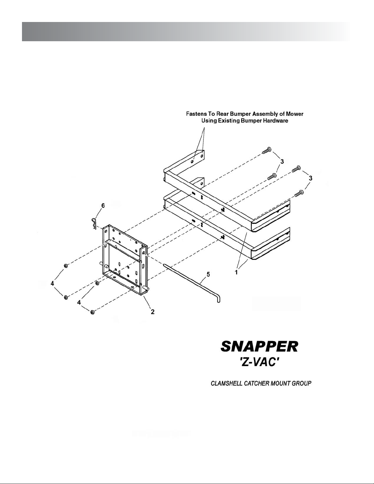
Snapper Z-Vac Clamshell Catcher Mount Group
Item Part No. Qty Description
1 50551 2 STANDOFF, Bumper Mount (weldment)
2 1723436 1 WELDMENT, Bumper Mount Plate
3 91318 4 SCREW, 5/16-18 x 3/4" Hex Head Cap, GR5
4 91601 4 NUT, 5/16-18 Hex Flange Lock, GR5
5 1717085 1 ROD, Hitch
6 15067 1 HAIR PIN, 3/32 x 1-1/2" Cotter
6
19
Page 20
6
unit breakdown & parts list
20
Page 21

unit breakdown & parts list
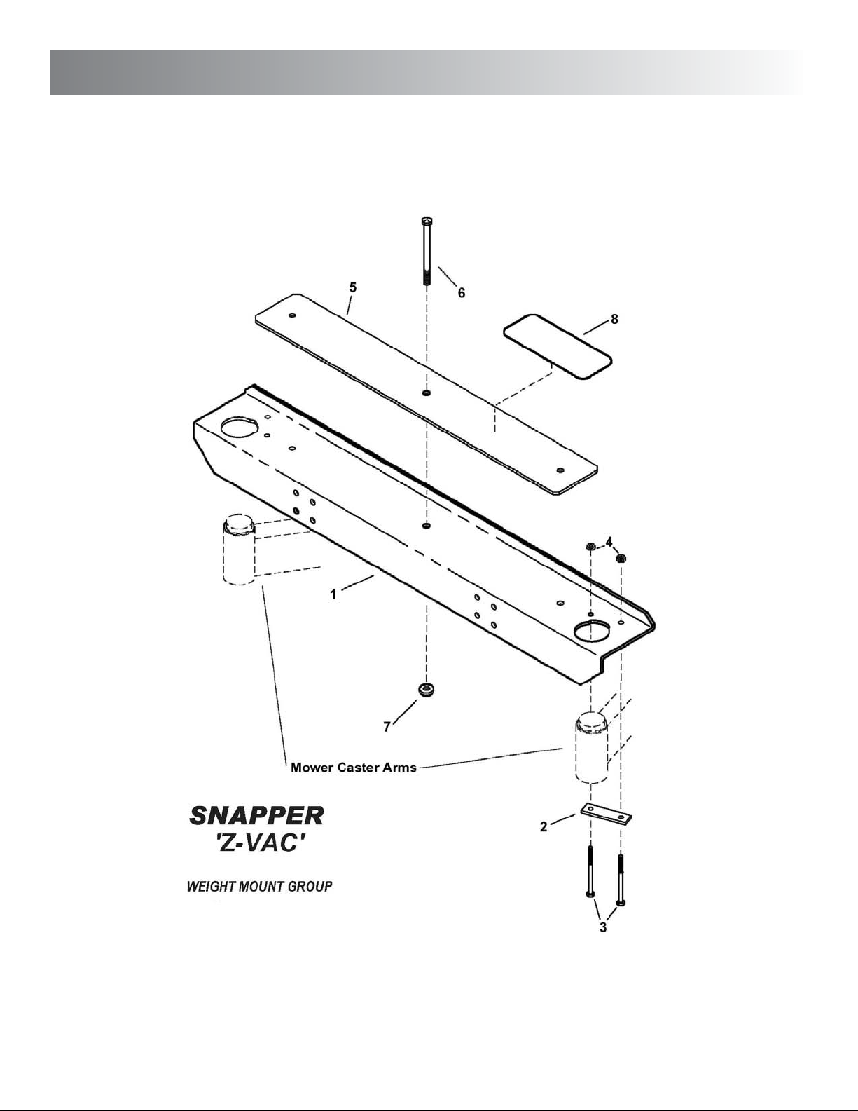
Snapper Z-Vac Weight Mount Group
Item Part No. Qty Description
1 3027501 1 CHANNEL, Weight Mounting
2 3046992 2 BAR, Clamp
3 91131 4 BOLT, 3/8-16 x 4" Hex Tap, GR5
4 90546 4 NUT, 3/8-16 Hex Center Lock, GR5 or B
5 3027502 26 BAR, Weight
6 92072 3 SCREW, 1/2-13 x 7-1/2" Hex Head Cap
7 90619 3 NUT, 1/2-13 Hex Flange Lock
8 3032142 2 PAD, Anti-Skid, Self-Adhesive
6
21
Page 22

6
unit breakdown & parts list
22
Page 23

unit breakdown & parts list
Item Part No. Qty Description
1 3079231 1 DECAL, Z-Vac
2 3046850 1 DECAL, Danger, Fast-Vac
3 3046851 1 DECAL, Warning, Fast Vac
4 3046883 1 DECAL, Warning, Fast-Vac
5 73956 1 DECAL, Warning, Billboard (on clamshell unit)
6
Snapper Z-Vac Decal Group
23
Page 24

ASSEMBLY INSTRUCTIONS
OPERATOR'S MANUAL
PARTS LIST
Z
-VAC
Large Clamshell
Grass Catcher Kit
for NZM
Mid Mount
Riders
McDonough, GA 30253 U.S.A.
Manual No. 7100651 (I.R. 4/5/2006)
TP 900-5178-IR-AT-N
 Loading...